Chapter 2 Thoracic imaging
ADULTS
CHEST RADIOGRAPHY AND OTHER TECHNIQUES
Different types of chest radiograph
Chest radiography has been used as the main radiological investigation of the chest since the discovery of X-rays by Röentgen in 1895 and chest radiographs constitute 25–40% of all radiological investigations. Chest radiographs are indicated in almost any condition in which a pulmonary abnormality is suspected.
The majority of chest radiographs are obtained in the main radiology department. The radiograph is obtained with the patient standing erect. Patients who are immobile or too ill to come to the main department have a chest radiograph performed using a mobile machine (portable film); the resulting radiograph differs from a departmental film in terms of projection, positioning, exposure and film used and is therefore not strictly comparable with a conventional posteroanterior (PA) film. Other types of chest radiograph are the lateral, lordotic, apical and decubitus views; these are generally taken in the main department.
Departmental films are referred to as ‘posteroanterior’ (or PA) chest radiographs and describe the direction in which the X-ray beam traverses the patient. The patient is positioned with his anterior chest wall against the film cassette and his back to the X-ray tube. The arms are abducted to rotate the scapulae away from the posterior chest and the radiograph is taken during full inspiration. The tube is centred at the spinous process of the fourth thoracic vertebra. For portable films taken in an anteroposterior (AP) projection, the patient’s back is against the film cassette and the X-ray tube is positioned at a variable distance from the patient. As the heart is placed anteriorly within the chest, it is further from the cassette and is therefore magnified in an AP radiograph. The degree of magnification depends on the distance between the patient and the X-ray tube.
For a lateral radiograph the patient is turned 90° and the side of interest placed against the film cassette. The arms are extended forwards and the radiograph is again taken in full inspiration.
Lateral decubitus views are sometimes useful for the demonstration of small pleural effusions. For this projection the patient lies horizontally with the side in question placed downwards. The film cassette is positioned at the back of the patient and the X-ray beam is horizontal centred at the midsternum. This provides a sensitive means of detecting small quantities of pleural fluid (50–100 ml) that cannot be identified on a frontal chest radiograph. However, ultrasonography is usually used as a reliable means of confirming the presence of small pleural effusions.
Lordotic films are sometimes used to confirm middle lobe collapse and for demonstrating a questionable apical opacity otherwise obscured by the clavicle and ribs. For this AP projection, the patient arches back so that the shoulders are touching the cassette with the centring point remaining the same. Linear tomography is another technique designed to reveal lesions otherwise hidden by the skeleton by blurring out everything overlying and underlying the lesion in question. This is achieved by having the X-ray tube and film cassette move at the same time but in opposite directions. These two techniques are less frequently used with the advent of computed tomography (CT).
Factors influencing the quality of a chest radiograph
The quality and thus diagnostic usefulness of a chest radiograph depend critically on the conditions under which it is obtained. Of particular importance are the radiographic exposure, the projection, the orientation of the patient relative to the film cassette, the X-ray tube to film distance, the depth of inspiration of the patient and the type of film–; combination used.
The ideal chest radiograph provides an image of structures within the chest while exposing the patient to the lowest possible dose of radiation. Most radio- logy departments have a policy of obtaining either high-kilovoltage (kVp) or low-kilovoltage chest radio- graphs. Radiographs performed at high kilovoltage (e.g. 140 kVp) have much to recommend them. Even at total lung capacity with the patient erect, nearly a third of the lungs is partially obscured by the mediastinal structures, diaphragm and ribs. With the low-kilovoltage technique (80 kVp or less) these areas are often poorly visualized. This problem is partially overcome by using films exposed at high kilovoltage. The normal vessel markings and subtle differences in soft tissue densities are better demonstrated and a further advantage is the better penetration of the mediastinum, which improves visualization of the trachea and main bronchi. The disadvantage of high-kilovoltage radiographs is the relatively poor demonstration of calcified structures so that rib fractures and calcified pulmonary nodules or pleural plaques are less conspicuous.
During exposure the X-ray beam is modified according to the structures through which it passes. The photons that have passed through the patient carry information which then must be converted into a visual form. Some of the photons emerging from the patient are aligned in a virtually parallel direction and other photons are scattered. These scattered photons degrade the final image but can be absorbed by using lead strips embedded in an aluminium sheet positioned in front of the cassette. This device is known as a grid. Photons that are travelling in parallel pass through the grid to form the image on the film.
The sensitivity of film to direct X-ray exposure is very low and if film were used alone as the image receptor, this would result in a prohibitively large X-ray dose to the patient. Intensifying screens made of phosphorescent material are positioned on the inside of the cassettes and they convert the incident X-ray photons into visible light, which is recorded by the adjacent film. These phosphor screens are composed of either calcium tungstate or a rare-earth-containing compound. Rare- earth phosphors emit more light in response to X-ray photons and therefore less radiation is necessary to produce the image. Similarly, improvements in the quality of X-ray film have also occurred over the years. Standard film emulsions tend to lack detail in the relatively under- or overexposed areas of the radiograph and newer emulsions have been developed so that detail is similar in all areas of the chest radiograph. The choice of film–; combination has a crucial influence on the quality and ‘look’ of the radiograph produced. Further variations may result from film-processing problems.
In the intensive care setting, portable chest radiographs are often taken in less than ideal conditions. Multiple tubes, lines and dressings in conjunction with an immobile, supine patient and the use of a mobile low- kilovoltage machine often result in suboptimal radiographs. One approach to this is the development of phosphor plate technology, which is ultimately expected to replace conventional film–; radiography. The phosphor plate is placed inside a conventional cassette and stores some of the energy of the incident X-ray photons as a latent image (the image produced on a film or phosphor plate before development). The plate is scanned with a laser beam and the light emitted from the ‘excited’ latent image is detected by a photomultiplier. Thereafter this signal is processed in digital form. This digital image may be viewed either on a television monitor or on film (on which it has been laser printed). The great advantage of this system is that it can retrieve an image of diagnostic quality from a suboptimal exposure. Similar gross over- or underexposure would result in a non-diagnostic conventional radiograph. Manipulation of the digital image, particularly ‘edge enhancement’, aids the detection of linear structures such as the edge of a pneumothorax or central venous catheters (Fig. 2.1). With the advent of picture archiving and communication systems (PACS), which enable storage and transfer of digital images, many radiology departments are now ‘filmless’, with images available to view simultaneously on monitors throughout the hospital.
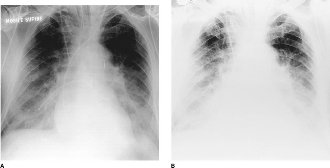
Figure 2.1 The same anteroposterior (AP) digital chest radiograph of a patient on the intensive care unit imaged on different settings. This technique has the advantage that the image can be made (A) darker or (B) lighter after it has been taken to allow better visualization of lines and tubes or lung parenchyma. Note the patient’s endotracheal tube, right internal jugular central line, pulmonary artery catheter and intra-aortic balloon pump.
Other techniques
Fluoroscopy
The patient is positioned, either standing or lying, in a screening unit allowing ‘real-time’ visualization of the area in question on a television monitor. The patient can be turned in any direction and this technique can help to distinguish pulmonary from extrapulmonary opacities. One of the main uses of fluoroscopy is to ‘screen’ the diaphragm to demonstrate paralysis or abnormal movement. It is also useful in needle placement during biopsy of lung masses.
Ultrasonography
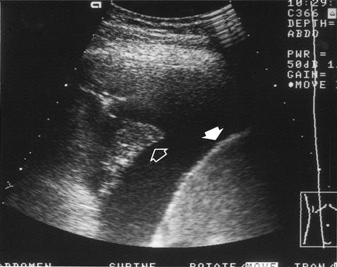
High-frequency sound waves do not traverse air and the use of this technique is therefore limited in the chest. It is mainly used for cardiac imaging (echocardiography) and has become an essential technique in the investigation of patients with valvular and ventricular function problems. Outside the heart, ultrasonography is very useful in distinguishing between fluid above the diaphragm (pleural effusion, Fig. 2.2), fluid below the diaphragm (subphrenic) and pleural thickening. Chest radiography often cannot differentiate between pleural fluid and thickening with any certainty. Ultrasound can also be used to guide the placement of a percutaneous drain into a pleural effusion or biopsy peripheral lung lesions that are in contact with the pleura.
Computed tomography
Computed tomography (CT) scanning depends on the same basic physical principle as conventional radiography, namely the absorption of X-rays by tissues of different densities. The basic components of a CT machine are a table on which the patient lies and a gantry through which the table slides. An X-ray tube and a series of detectors are housed within the gantry. The X-ray tube and detectors rotate around the patient. A computer is used to reconstruct the signals received by the detectors into an image. The images acquired are transverse (axial) cross-sections of the patient. In orienting the patient’s right and left sides, it is the convention to view all CT images as if from the patient’s feet.
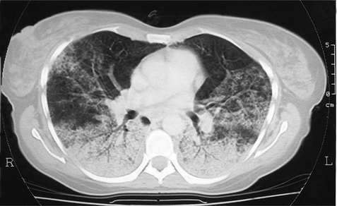
Because of the cross-sectional nature of CT, it can accurately localize lesions seen on only one view on plain chest radiographs. The superior contrast resolution of CT allows superb demonstration of mediastinal anatomy (e.g. lymph nodes and vessels) (Fig. 2.3) as well as calcification within a pulmonary nodule. Highly detailed thin sections of the lung parenchyma can also be obtained, allowing the complex morphology of many interstitial lung diseases to be more accurately defined. The disadvantages of CT are its relatively high cost and increased radiation exposure to the patient compared with chest radiography.
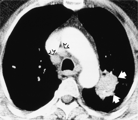
Figure 2.3 Computed tomography (CT) image postintravenous contrast showing a lung tumour adjacent to the arch of the aorta (closed arrows). Lymph nodes are seen anterior to the trachea (open arrows), which were not visible on chest radiography.
Whereas conventional CT scanning involves alternating table movement through the gantry with exposure, helical or volumetric CT involves simultaneous table movement and X-ray exposure. The technique allows faster scan times and advantages are the elimination of respiratory artefacts, minimization of motion artefacts and production of overlapping images without additional radiation exposure. Helical (spiral) CT is so named because the X-ray can be thought of as tracing a helix or spiral curve on the patient’s surface. Multiple rows of detectors are used in the newer helical CTs, so-called multidetector CT (MDCT). The technique allows viewing of images in multiple planes (Fig. 2.4) and, due to the very fast acquisition times, is increasingly used to evaluate cardiac structures such as the coronary arteries. Helical CT is also now commonly used to demonstrate pulmonary emboli, as accurate timing of a bolus of intravenous contrast allows optimal enhancement of the pulmonary arteries (Fig. 2.5).
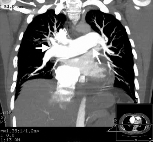
Figure 2.4 Example of coronal reconstruction of multidetector helical CT (MDCT) in a patient with primary pulmonary hypertension. Note the enlarged central pulmonary arteries (arrows).
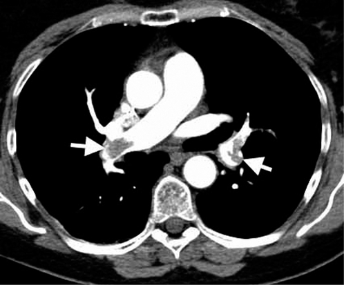
Figure 2.5 A CT pulmonary angiogram, showing bilateral filling defects of the pulmonary arteries (arrows) consistent with bilateral pulmonary emboli.
Common indications for CT of the chest
Magnetic resonance imaging
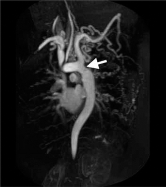
The physical principles of magnetic resonance imaging (MRI) are more complex and very different from those of CT scanning. The equipment consists of a sliding table on which the patient lies within the bore of a large magnet. A combination of the intense magnetic field and a series of radiofrequency waves produces an alteration in the alignment of protons (mostly in water) resulting in the emission of different signals which are detected and subsequently analysed for their intensity and position by a computer. The major advantages of MRI are that images may be obtained in any plane without the use of ionizing radiation. The disadvantages are its inability to produce detailed images of the lung, cost and reduced acceptability to patients because of the claustrophobic bore of the magnet. There are also important contraindications such as permanent cardiac pacemaker devices. Its application to chest imaging is limited at present but the technique is good for imaging chest wall lesions, the great vessels (Fig. 2.6) and the heart.
Radionuclide imaging
Ventilation–perfusion ( ) scanning is the commonest radionuclide study of the lungs. It is primarily used to investigate suspected pulmonary embolus. Perfusion is assessed by intravenous injection of minute particles labelled with technetium-99m, a radioactive tracer. These particles become temporarily lodged in a very small proportion of capillaries within the lung and the emitted radiation is detected by a so-called gamma camera. Ventilation is assessed by the inhalation of inert gases that have also been labelled with a radioactive tracer. The ventilation and perfusion images are then compared to see if there are any areas of mismatch (Fig. 2.7). Increasingly CT is used to investigate patients with possible pulmonary embolus, as scanning is more difficult to interpret in patients with coexisting lung disease such as asthma. In addition, the tracers have a short period of radioactivity after they are produced of a few hours and therefore scanning late at night and at weekends may be difficult.
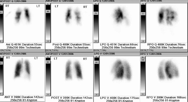
Figure 2.7 Example of a radionuclide lung ventilation and perfusion scan. The examination shows a high probability for multiple bilateral pulmonary emboli as there are multiple perfusion abnormalities (top row of images) with no matched ventilation defects (bottom row of images), so-called ‘mismatched’ defects.
Positron emission tomography
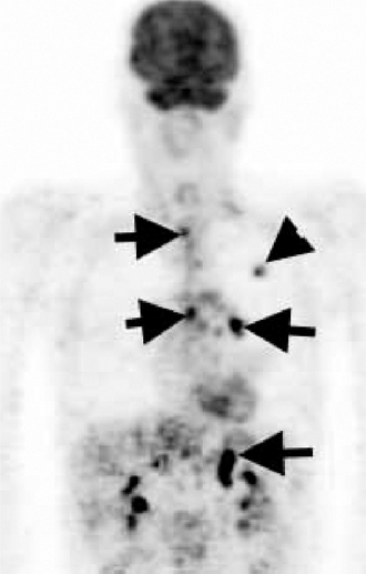
Positron emission tomography (PET) is also a form of radionuclide imaging. A detector can pinpoint where there is uptake of tracer accurately within the body. PET highlights areas that are very metabolically active, such as cancers, but also infection and inflammation. Access to this type of costly scanner is becoming more widespread, and it is mainly used in the chest for assessment of disease spread of lung cancer to lymph nodes and sites outside the chest (Fig. 2.8). The images may be fused with CT images (PET/CT) to give a very precise location of tumour spread.
Interventional procedures
Percutaneous needle biopsy
Percutaneous needle biopsy of a pulmonary or mediastinal mass to provide a histological specimen is usually performed in patients in whom a bronchoscopic biopsy has failed or a thoracotomy is inappropriate. Different types of needle are used and the complication rate (pneumothorax and haemoptysis) bears some relation to the site of the lesion, the size of the needle and the number of attempts to obtain tissue. Contraindications to the procedure include any patient with poor respiratory reserve unable to withstand a pneumothorax, pulmonary arterial hypertension and a previous contra- lateral pneumonectomy.
Pulmonary and bronchial arteriography, superior vena cavography
Pulmonary arteriography.
This is usually undertaken in the investigation of suspected pulmonary arteriovenous malformations and, less commonly since the development of helical (spiral) CT, pulmonary embolism. It requires puncture of either the femoral vein in the groin or the antecubital vein in the elbow and the guiding of a catheter through the right side of the heart under fluoroscopy. The tip of the catheter is positioned in the main pulmonary artery or selectively placed in a smaller pulmonary artery. Contrast is then injected. It is currently the most appropriate technique for the demonstration of pulmonary arteriovenous malformations. These can be treated at the time of the arteriogram by the injection of occlusive materials (embolization).
Bronchial arteriography.
Demonstration of the bronchial arteries requires catheterization of the femoral artery and passage of a catheter into the midthoracic aorta from where the bronchial arteries are selectively catheterized. The major indication for this procedure is recurrent or life-threatening haemoptysis in patients with a chronic inflammatory disease, usually bronchiectasis. Accurate placement of the catheter not only allows demonstration of the bleeding vessel but also allows embolization to be performed simultaneously.
Superior vena cavography.
This is performed for the evaluation of superior vena caval (SVC) obstruction and the investigation of anatomical variants. More recently, patients with SVC compression due to tumour have been palliated by the insertion of an expandable metallic mesh wire stent at the site of the SVC narrowing, thus restoring flow and relieving symptoms.
THE NORMAL CHEST
Anatomy
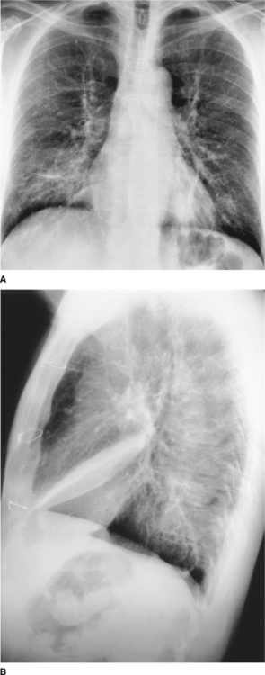
On the normal posteroanterior radiograph (Fig. 2.9) the following structures can be identified:
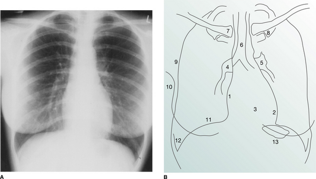
Figure 2.9 (A) Normal posteroanterior (PA) chest radiograph. (B) Normal structures visible on a PA chest radiograph: 1 right atrium; 2 left ventricle; 3 right ventricle; 4 right pulmonary artery; 5 left pulmonary artery; 6 air within trachea; 7 clavicle; 8 first rib; 9 lateral border of hemithorax; 10 breast shadow; 11 right hemidiaphragm; 12 costophrenic angle; 13 gastric air bubble.
The heart and mediastinum
The mediastinum consists of the organs and soft tissues in the central part of the chest. These comprise the trachea, aortic arch and great vessels, superior vena cava and oesophagus. In children the thymus gland is a prominent component. On the two-dimensional chest radiograph these structures are superimposed and cannot be clearly distinguished from each other. The mediastinum is conventionally divided into superior, anterior, middle and posterior compartments. While the boundaries of the latter three are arbitrary, it is usual to divide the mediastinum into equal thirds. The superior mediastinum is that portion lying above the aortic arch and below the root of the neck.
The mediastinal border on the right is formed superiorly by the right brachiocephalic vein and superior vena cava. The mediastinal shadow to the left of the trachea above the aortic arch comprises the left carotid and left subclavian arteries together with the left brachiocephalic and jugular veins. On a correctly exposed chest radiograph, air in the trachea can be seen throughout its length as it descends downwards, deviating slightly to the right above the carina (where the trachea divides into the right and left main bronchi) due to displacement by the aortic arch.
The heart lies eccentrically in the chest, with one-third of the cardiac shadow to the right of the spine and two-thirds to the left. The density of the cardiac shadow on the left and right of the spine should be identical. The right cardiac border on a chest radiograph is formed by the right atrium. The left cardiac border is composed of the apex of the left ventricle and superiorly the left atrial appendage. The outline of the right ventricle, which is superimposed on the left ventricle, cannot be identified on a frontal radiograph. The maximum transverse diameter of the heart should be less than half the maximum transverse diameter of the thorax, as measured from the inside border of the ribs (the so-called ‘cardiothoracic ratio’).
The hila
Hilar shadows are a complex summation of the pulmonary arteries and veins with minor contributions from other components (the main bronchi and lymph nodes). In general, the hila are of equal density and are approximately the same size. Adjacent to the left hilum, the main pulmonary artery forms a localized bulge just above the left atrial appendage and just below the aortic arch. The area between the aortic arch and the main pulmonary artery is known as the ‘aortopulmonary window’.
The superior pulmonary veins run vertically and converge on the upper and mid-hilum on both sides. It is not possible to distinguish arteries from veins in the outer two-thirds of the lungs. The inferior pulmonary veins run obliquely in a near-horizontal plane below the lower lobe arteries to enter the left atrium beneath the carina. The hilar point is where the superior pulmonary vein on each side crosses the basal artery. This is more easily assessed on the right than on the left. Using this as an index point, the left hilum is normally 0.5–1.5 cm higher than the right one.
Abnormalities of the hilar shadows in the form of increased density or abnormal configuration are usually the result of lymph node or pulmonary artery enlargement. The detection of subtle hilar abnormalities is difficult and requires experience and knowledge of the many outlines that the hila may assume in normal individuals.
Fissures, vessels and segmental bronchi within the lungs
Each lung is divided into lobes surrounded by visceral pleura. There are two lobes on the left (the upper and lower, separated by the major (oblique) fissure) and three on the right (the upper, middle and lower lobes which are separated by the major (oblique) and minor (horizontal or transverse) fissures). In the majority of normal subjects some or all of the minor fissure is seen on a frontal radiograph. The major fissures are only identifiable on the lateral projection. Each lobe of the lung contains a number of segments, which have their own segmental bronchi. The walls of the segmental bronchi are invisible on the chest radiograph, except when seen end-on as ring shadows measuring up to 7 mm in diameter.
The pulmonary blood vessels are responsible for the branching and linear structures within the lungs. The diameter of the blood vessels beyond the hilum varies with the position of the patient and with haemodynamic factors. In the erect position there is a gradual increase in the diameter of the vessels, travelling from apex to base. This increase in size is seen in both the arteries and veins and is abolished if the patient lies supine.
The diaphragm
The interface between the lung and diaphragm should be sharp and, in general, the diaphragm is dome shaped with its highest point medial to the midclavicular line. The margin of the right hemidiaphragm at its highest point lies between the anterior ends of the fifth and seventh ribs. The right hemidiaphragm is usually higher than the left by up to 2 cm in the erect position. Laterally, the diaphragm dips downwards, forming a sharp angle with the chest wall known as the ‘costophrenic angle’. Filling in or blunting of these angles reflects pleural disease, either fluid or thickening.
Thoracic cage
On a high-kilovoltage chest radiograph it should be possible to identify the edges of the vertebral bodies of the dorsal spine through the heart shadow. However, a high-kilovoltage radiograph may ‘burn out’ the ribs, particularly the posterior portions. Because of this the chest radiograph may be an insensitive means of demonstrating rib abnormalities, particularly fractures.
Common anatomical variants
The trachea lies centrally, but in the elderly may deviate markedly to the right in its lower portion due to unfolding and dilatation of the aortic arch. A small ovoid soft tissue shadow just above the origin of the right main bronchus represents the azygos vein. This may be enlarged as a result of posture (supine position) or haemodynamic factors. It may be indistinguishable from an azygos lymph node.
Occasionally, extra fissures are seen in the lungs. The most common of these is the azygos lobe fissure; this is seen as a fine white line running obliquely from the apex of the right lung to the azygos vein. Other accessory fissures are the superior and inferior accessory fissures, both of which are in the right lower lobe.
The surfaces of the two lungs abut each other anteriorly and posteriorly and give rise to two white lines projected over the vertebral column, known as the ‘anterior and posterior junction lines’, respectively. Both of these may be seen overlying the trachea – the anterior line extending from the clavicles to the left main bronchus and the posterior line lying more medially and extending above the clavicles. The azygo-oesophageal recess line is a curved line projected over the vertebral column and extending from the azygos vein to the diaphragm. It represents the interface between the right lung and right oesophageal wall.
A small ‘nipple’ may occasionally be seen projecting laterally from the aortic knuckle due to the left superior intercostal vein. The term ‘paraspinal line’ refers to the line that parallels the left and right margin of the thoracic spine. The left is thicker than the right because of the adjacent aorta.
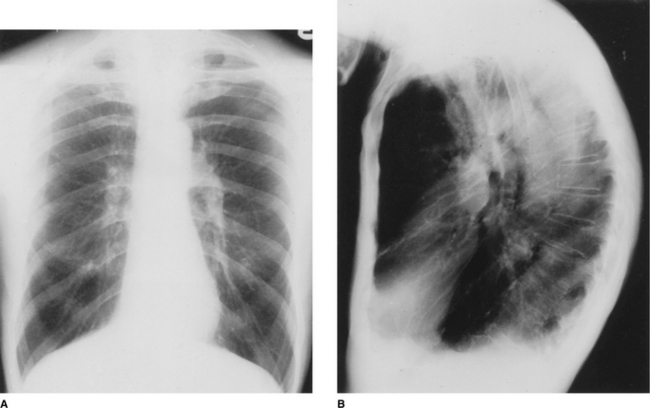
The lateral view
It is conventional to read the lateral film (Fig. 2.10) with the heart to the viewer’s left and the dorsal spine to the right, irrespective of whether the film is labelled ‘right’ or ‘left’. The chamber of the heart that touches the sternum is the right ventricle. Behind and above the heart lies lung, the density of which should be the same both behind the heart and behind the sternum. As the eye travels down the spine, the vertebral column should appear increasingly transradiant or ‘dark’ (Fig. 2.10A); the loss of this phenomenon suggests the presence of disease in the posterobasal segments of the lower lobes. In the middle of the lateral film lie the hilar structures with the main pulmonary artery anteriorly. The aortic arch should be easily identified but only a variable proportion of the great vessels is visible depending on the degree of aortic unfolding. The brachiocephalic artery is most frequently identified arising anterior to the tracheal air column. The left and right brachiocephalic veins form an extrapleural bulge behind the upper sternum in about a third of individuals.
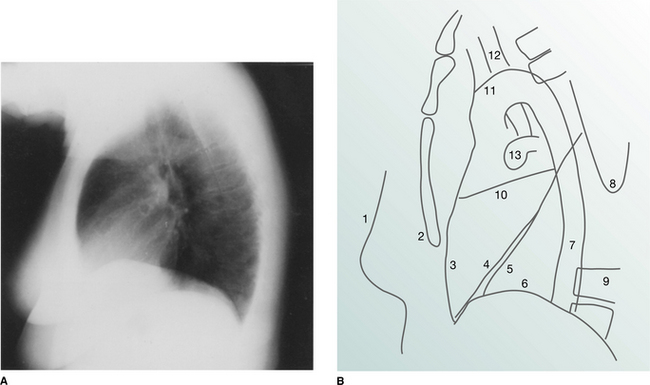
Figure 2.10 (A) Normal lateral chest radiograph. (B) Normal structures visible on a lateral chest radiograph: 1 breast shadow; 2 sternum; 3 position of right ventricle; 4 right oblique fissure; 5 left oblique fissure; 6 hemidiaphragm; 7 descending aorta; 8 inferior angle of scapula; 9 dorsal vertebrae; 10 horizontal fissure; 11 aortic arch; 12 trachea; 13 pulmonary artery.
The course of the trachea is straight with a slight posterior angulation but no visible indentation from adjacent vessels. The carina is not seen on the lateral view. The posterior wall of the trachea is always visible and is known as the ‘posterior tracheal stripe’.
The oblique fissures are seen as fine diagonal lines running from the upper dorsal spine to the diaphragm anteriorly. The left is more vertically oriented and is visible just behind the right. The minor fissure extends forwards horizontally from the mid-right oblique fissure. Care must be taken not to confuse rib margins with fissure lines. As the fissures undulate, two distinct fissure lines may be generated by a single fissure. The fissures should be of no more than hairline width.
The scapulae are invariably seen in the lateral view and since they are incompletely visualized, lines formed by the edge of the scapula can easily be confused with intrathoracic structures. The arms are held outstretched in front of the patient on a lateral view and these give rise to soft tissue shadows projected over the anterior and superior mediastinum. A band-like opacity simulating pleural disease is often seen along the lower half of the anterior chest wall immediately behind the sternum. The left lung does not contact the most anterior portion of the left thoracic cavity at these levels because the heart occupies the space. This band-like opacity is known as the ‘retrosternal line’.
Useful points in interpreting a chest radiograph
Documentary information.
The name of the patient and the time and date on which the radiograph was taken, particularly in relation to other films in a series, should all be noted. Often the film is annotated with the patient’s date of birth. Of particular importance is the presence of the side markers (‘right’ or ‘left’). The radiograph should also be marked ‘AP’ if the anteroposterior projection was used; departmental posteroanterior (PA) films are generally not marked as such.
Radiographic projection.
A judgement as to whether a radiograph is AP or PA can be made from the following evidence:
Supine versus prone position.
It is important to know whether a chest radiograph was taken in the erect or supine position. In the supine position, blood flow is more evenly distributed throughout the lungs, making the upper zone vessels equal in size to those in the lower zones. This has implications in assessing the chest radiograph of a patient suspected of being in cardiac failure. In addition, fluid is distributed throughout the dependent part of the pleural space and any air–fluid levels that might be present on an erect film are impossible to detect. The position and contours of the heart, mediastinum and diaphragm are also different compared with an erect film. In the absence of any indication on the radiograph, one clue is the position of the gastric air bubble: if it is just under the left hemidiaphragm it is in the fundus and the patient is erect, whereas in the supine position air collects in the antrum of the stomach which lies centrally or slightly to the right of the vertebral column, well below the diaphragm.
Patient rotation.
The patient may be rotated around one of three axes. Axial rotation is the most common cause of unilateral transradiancy (one lung appearing darker than the other). It also distorts the mediastinal outline. The degree of rotation can be assessed by relating the medial ends of the clavicles to the spinous process of the vertebral body at the same level – they should be equidistant from the spinous processes.
Rotation about the horizontal coronal axis results in a more kyphotic or lordotic projection than normal. The main pulmonary artery and subclavian vessels may appear unduly prominent. Rotation around the horizontal sagittal axis usually leads to obvious tilt of the chest in relation to the edge of the radiograph, which is assumed to be upright.
Physical attributes of the patient, such as a kyphoscoliosis or a depressed sternum (pectus excavatum), may also distort the appearance of the thoracic cage and its contents.
State of inspiration or expiration.
The degree of inspiration is an important consideration for the correct interpretation of a chest radiograph. A poor inspiratory effort does not necessarily imply lack of patient cooperation and may as often be related to a pathological process. At full inspiration the midpoint of the right hemidiaphragm lies between the anterior end of ribs 5–7. A shallow inspiration affects the contour of the heart and mediastinum and may mimic the appearances of pulmonary congestion because the upper zone vessels will have the same diameter as the lower zone vessels.
Films taken deliberately with the patient in full expiration are invaluable in the investigation of air trapping. They are mandatory in any patient suspected of having inhaled a foreign body with consequent obstruction of a lobar bronchus. An expiratory film is also useful in accentuating a small pneumothorax.
Review areas.
Several areas are difficult to assess on a frontal radiograph and should be scrutinized carefully. These review areas are:
Detection and description of radiographic abnormalities should then be undertaken and a differential diagnosis listed based on the abnormalities detected. With experience, the structured search gives way to the rapid identification of abnormalities and a search for confirmatory radiological signs and associated abnormalities.
COMMON RADIOLOGICAL SIGNS
Consolidation
‘Consolidation’ is the term used to describe lung in which the air-filled spaces are replaced by the products of disease, e.g. water, pus or blood. The two most important radiological signs of consolidation are (a) an air bronchogram and (b) the silhouette sign. The causes of widespread consolidation may be divided into four categories (Box 2.1).
Box 2.1 Causes of widespread pulmonary consolidation
| Fluid transudation | Pulmonary oedema due to cardiac failure, renal failure, hepatic failure |
| Exudation | |
| Inhalation | |
| Infiltration |
An air bronchogram is present when the airways contain air and appear as radiolucent (black) branching structures against a now white background of airless lung. The silhouette sign is present when the border of a structure is lost because the normally air-filled lung outlining the border is replaced by radio-opaque fluid or tissue. Recognition of this sign can help localize the affected area of abnormality within the chest. Thus, loss of a clear right heart border is due to right middle lobe consolidation or collapse.
Localized areas of consolidation are usually due to infection. In some cases the borders of the consolidation are clearly demarcated. This usually corresponds to a fissure and the consolidation is confined to one lobe (lobar pneumonia) (Fig. 2.11). If consolidation is slow to clear with treatment, it may be secondary to partial obstruction of a lobar bronchus, such as carcinoma of the bronchus. Consolidation may also be widespread and affect both lungs (Figs. 2.12, 2.13).
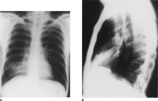
Figure 2.11 Right middle lobe consolidation. (A) The right heart border is not seen clearly, owing to adjacent consolidation. Note that the right hemidiaphragm is clearly visible as far as the vertebral column. (B) The lateral view confirms the presence of consolidation in the right middle lobe with the posterior aspect well demarcated by the oblique fissure.
Collapse (atelectasis)
‘Collapse’ (atelectasis) is the radiological term used when there is loss of aeration and, therefore, expansion in part or all of a lung. Collapse of a lobe or an entire lung is most frequently due to an endobronchial tumour, an inhaled foreign body or a mucus plug.
Although collapse is most often thought of as occurring at a lobar level, focal areas of pulmonary collapse at a subsegmental level occur very commonly in postoperative patients. There are many signs of lobar collapse but it is important to realize that not all these signs occur together. In addition, some non-specific signs may be present which indirectly point to the diagnosis and alert the observer to look for the more specific signs.
The most reliable and frequently present finding in lobar collapse is shift of the fissures, which invariably occurs to some extent. If air stays in the collapsed lobe, the contained blood vessels remain visible and appear crowded. If there is marked volume loss, the density of the collapsed and airless lobe increases. The hila may show two types of change consisting either of gross displacement upwards or downwards, or of rearrangement of individual hilar components (i.e. vessels and airways) leading to changes in shape and prominence. Elevation of the hemidiaphragm, reflecting volume loss, is most marked in collapse of a lower lobe. ‘Peaking’ of the mid-portion of the hemidiaphragm occurs in upper lobe collapse due to displacement of the oblique fissure. The signs associated with collapse are listed in Box 2.2.
Collapse of individual lobes
Right upper lobe
On the PA radiograph there is elevation of the transverse fissure and the right hilum. If the collapse is complete the non-aerated lobe is seen as an increased density alongside the superior mediastinum adjacent to the trachea (Fig. 2.14). On the lateral view the minor fissure moves upwards and the major fissure moves forwards. The retrosternal area becomes progressively more opaque and the anterior margin of the ascending aorta becomes effaced.
Right middle lobe
On the PA radiograph the lateral part of the minor fissure moves down and there is blurring of the normally sharp right heart border. This may be a subtle abnormality that is easily overlooked. On the lateral view the minor fissure moves downwards and the lower half of the major fissure moves forwards, giving rise to a triangular shadow visible behind the lower sternum (Fig. 2.15).
Right lower lobe
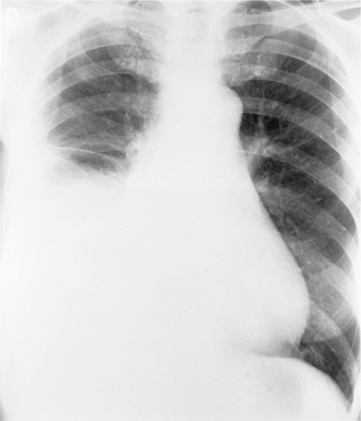
On the PA view there is an increase in density overlying the medial portion of the right hemidiaphragm and the right hilum is displaced inferiorly. The right heart border usually remains sharply defined since this is in contact with the aerated right middle lobe. On the lateral view the oblique fissure moves backwards and, with increasing collapse, there is loss of definition of the right hemidiaphragm as well as increased density overlying the lower dorsal vertebrae. Right lower lobe collapse is a mirror image of left lower lobe collapse (Fig. 2.16).
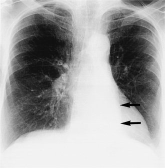
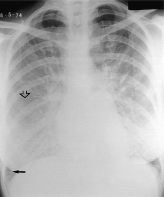
Figure 2.16 Left lower lobe collapse. A PA radiograph shows loss of the outline of the medial portion of the left hemidiaphragm and a triangular density behind the left side of the heart (arrows). There is also volume loss of the left hemithorax and the mediastinum is deviated to the left, allowing increased visibility of the thoracic spine.
Left upper lobe
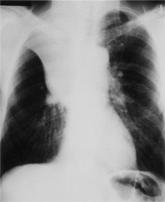
The main finding on the PA radiograph is of a veil-like increase in density, without a sharp margin, spreading outwards and upwards from the left hilum, which is elevated. The aortic knuckle, left hilum and left heart border may have ill-defined outlines. As volume loss increases, the collapsed lobe moves closer to the midline and the lung apex may become lucent due to hyperinflation of the apical segment of the left lower lobe. A sharp border may also return to the aortic arch. On the lateral view the oblique fissure moves upwards and forwards, remaining relatively straight and roughly parallel to the anterior chest wall (Fig. 2.17). On the PA projection, collapse (or consolidation) of the lingular segment of the left upper lobe should be suspected when the left cardiac border is ill defined.
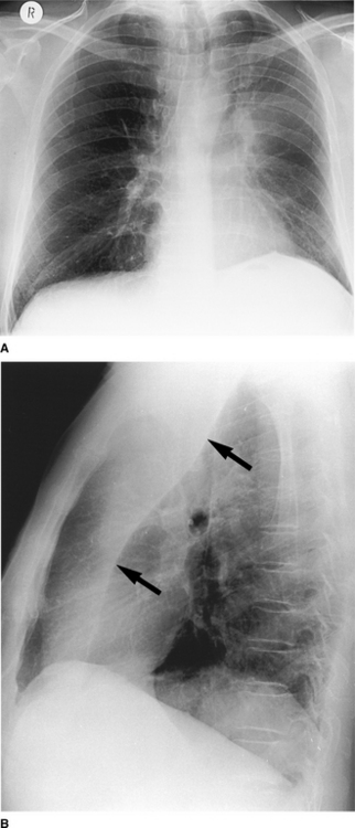
Figure 2.17 Left upper lobe collapse. (A) There is a veillike density of the left hemithorax, which obscures the outline of the aortic knuckle and left heart border superiorly. There is also volume loss on the left (the trachea is deviated to the left and the left hemidiaphragm is raised with ‘peaking’ centrally). (B) The lateral radiograph shows increased density anterior to the oblique fissure (arrows).
Left lower lobe
This is most commonly seen in patients following cardiac surgery and a thoracotomy due to the retention of secretions in the left lower lobe bronchus. On the PA view there is a triangular density behind the heart with loss of the medial portion of the left hemidiaphragm (Fig. 2.16); if the PA radiograph is underexposed, it may be impossible to see this triangular opacity. On the lateral view there is backwards displacement of the oblique fissure and with increasing collapse there is increased density over the lower dorsal vertebrae.
Pneumothorax
When air is introduced into the pleural space, the resulting pneumothorax can be recognized radiographically. There are numerous causes of a pneumothorax but the most common include penetrating injuries (e.g. stab wound, placement of a subclavian line) and breaches of the visceral pleura (e.g. spontaneous rupture of a subpleural bulla or mechanical ventilation with high pressures). The cardinal radiographic sign is the visceral pleural edge: lateral to this edge no vascular shadows are visible and medial to it the collapsed lung is of higher density than the contralateral lung (Fig. 2.18). It is important to remember that in the supine position, the air of a small pneumothorax will collect anteriorly in the pleural space; thus on a portable supine chest radiograph, the pneumothorax will be visible as an area of relative translucency without a visceral pleural edge necessarily being identifiable.
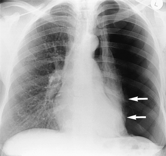
Figure 2.18 Spontaneous pneumothorax. There is a large left-sided pneumothorax with loss of vascular markings lateral to the edge of the collapsed lung. The visceral pleural edge is visible (arrows).
If air enters the pleural space during inspiration but cannot leave on expiration (usually because of a check-valve effect of the torn flap of the visceral pleura), pressure increases rapidly and this results in a life-threatening tension pneumothorax. This can be recognized by a shift of the mediastinum to the opposite side (Fig. 2.19).
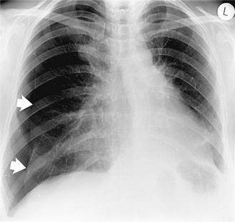
Figure 2.19 Tension pneumothorax post-thoracoscopic biopsy of a right upper zone lung nodule. The pneumothorax in Figure 2.18 involves more of the hemithorax but this pneumothorax is causing deviation of the mediastinum to the opposite side and is potentially life threatening unless treated promptly. The visceral pleural edge is visible (arrows).
The opaque hemithorax
If one-half of a chest is completely opaque (a white-out) it is due either to collapse of a lung or a large pleural effusion. If there is a shift of the mediastinum to the affected side it implies that volume loss in the lung (i.e. collapse) on that side must have occurred. Where there is no shift of the mediastinum or it is shifted slightly to the side of the white-out, this is usually due to constricting pleural disease (including pleural tumour). A pleural effusion that is large enough to cause complete opacification of a hemithorax will displace the mediastinum away from the side of the white-out. While penetrated PA and lateral films may help, it is sometimes surprisingly difficult to differentiate between the causes of an opaque hemithorax. Ultrasound and computed tomography allow the distinction to be made with confidence and the latter may give further information about the underlying disease.
Decreased density of a hemithorax
The conditions outlined so far have all focused on increased density of the lungs on plain radiographs. However, there are a number of causes where one lung appears less dense than the other side. When a chest radiograph demonstrates greater radiolucency of one lung compared with the other, it is necessary first to determine whether this appearance is due to a pulmonary abnormality. The radiograph should be checked for patient rotation and for soft tissue asymmetry, e.g. a mastectomy.
The pulmonary vessels are a helpful pointer to abnormalities causing a true decrease in density. In compensatory hyperinflation they are splayed apart. A search should also be made for a collapsed lobe. The vessels are considerably diminished or truncated in emphysema. Further radiological examination should include an expiration film if a pneumothorax is suspected. This will also demonstrate air trapping that occurs with bronchial obstruction. Computed tomography may also be useful in elucidating the cause of a hyperlucent lung. The lungs can be seen on computed tomography without the problem of overlying tissues and any decrease in density is more readily apparent.
Elevation of the diaphragm
The right or left dome of the diaphragm may be elevated because it is paralysed, pushed up or pulled up. How-ever, there are a number of circumstances in which the diaphragm appears to be elevated without actually being so.
The radiographic evaluation of an apparently elevated diaphragm should begin with an assessment of the plain film, in particular evidence of previous surgery. Old radiographs are essential to determine whether the diaphragmatic elevation is of long standing. A decubitus film is particularly useful in ruling out a suspected subpulmonary effusion; in this instance the pleural effusion is confined to the space between the lung base and the superior surface of the diaphragm. The radiograph will show what appears to be an elevated hemidiaphragm. Ultrasound will assist in determining if fluid is present above and/or below the diaphragm.
If the hemidiaphragm is paralysed, fluoroscopic or ultrasound examination is useful as it may demonstrate paradoxical movement on vigorous sniffing (instead of the diaphragm moving down, it moves up). An important proviso is that a few normal individuals show this paradoxical movement of the diaphragm on sniffing. In congenital eventration part or all of the hemidiaphragm muscle is made up of a thin layer of fibrous tissue and it may be difficult to distinguish from paralysis even on fluoroscopy.
Pleural disease
Because the chest radiograph is a two-dimensional image, abnormalities of the pleura and chest wall are often difficult to assess. Gross pleural abnormalities are usually obvious on a chest radiograph (Fig. 2.20), but even when there is extensive pleural pathology it may be difficult to distinguish between pleural fluid, pleural thickening (e.g. secondary to a previous inflammatory process) and a neoplasm of the pleura. In such cases, a lateral decubitus film or ultrasound scan is useful in identifying the presence of fluid. Computed tomography can readily identify the encasing and constricting nature of a mesothelioma.
The pulmonary mass
Most pulmonary nodules or masses are discovered by plain chest radiography. It is important to obtain previous films if at all possible. If the mass was present on the previous films and has not changed over a number of years, it can be assumed that the lesion is benign and no further action needs to be taken. However, if the nodule was not previously present or has increased in size, further investigation is warranted.
Computed tomography (see Fig. 2.3) will detect or exclude the presence of other lesions within the lungs. The presence of calcification within the nodule, although often thought to be an indicator of benignity, will not exclude malignancy with complete certainty. In addition, computed tomography can be used to determine the presence of hilar or mediastinal lymph node enlargement as well as direct invasion of the adjacent mediastinum or chest wall. In patients in whom surgical resection of the pulmonary mass is not indicated, a cyto logical or histological specimen by percutaneous needle biopsy may be taken. This is usually reserved for small peripheral lesions that are not accessible by bronchoscopy. It can be performed under computed tomography guidance or fluoroscopy but complications include pneumothorax or pulmonary haemorrhage (see other interventional techniques).
Pulmonary nodules
A large number of conditions are characterized by multiple pulmonary nodules (Fig. 2.21). Combining the clinical information with an accurate description of the size and distribution of the nodules narrows down the list of differential diagnoses.
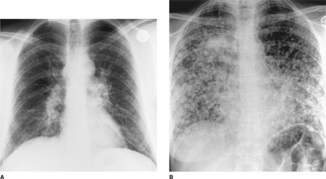
Figure 2.21 Multiple pulmonary nodules. (A) Pulmonary sarcoidosis. These pulmonary nodules are small (2–3 mm) and subtle and there is bilateral hilar lymphadenopathy. (B) Multiple pulmonary metastases. These nodules are better defined, larger (most 0.5–1 cm in diameter) and are so numerous that they have coalesced in the right upper zone.
Metastatic deposits are by far the most common cause of multiple pulmonary nodules of varying sizes in adult patients in the United Kingdom (Fig. 2.21) but this is not the case worldwide. In some parts of the USA, histoplasmosis is endemic and multiple lesions due to this condition may be more common than those due to malignancy. Making this important distinction may be difficult and biopsy of one lesion may be the only reliable means of distinguishing a benign from a malignant cause for the multiple nodules.
Nodules are described as ‘miliary’ when they are less than 5 mm in diameter and are so numerous that they cannot be counted. The crucial diagnosis to consider, even if the patient is not particularly unwell, is miliary tuberculosis, since this life-threatening disease can be readily treated. If the patient is asymptomatic the differential diagnosis is more likely to lie between sarcoidosis, metastatic disease or a coal worker’s pneumoconiosis. As ever, previous radiographs showing the rate of growth of the nodules may give valuable clues to the likely nature of the disease.
Cavitating pulmonary lesions
The radiological definition of cavitation is a lucency representing air within a mass or an area of consolidation. The cavity may or may not contain a fluid level and is surrounded by a wall of variable thickness (Fig. 2.22).
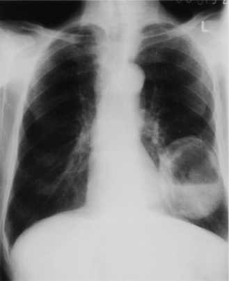
Figure 2.22 Lung abscess: there is a thick-walled cavity containing a fluid level in the left lower lobe.
The two most likely diagnoses in an adult presenting with a cavitating pulmonary lesion on a chest radiograph are a cancer or a lung abscess. In children, infection is the most common cause. Cavitation secondary to necrosis is well recognized in a variety of bacterial pneumonias, particularly those associated with tuberculosis, Staphylococcus aureus, anaerobes and Klebsiella. Diagnosis is usually by plain chest radiograph in the first instance but computed tomography is also useful for localizing the abscess and sometimes to enable percutaneous aspiration to be undertaken. It also allows assessment of the relationship of the abscess to adjacent airways so that appropriate postural drainage can be planned.
In all age groups it is important to consider tuberculosis, especially if the cavitating lesions are in the lung apices. Linear or computed tomography may be necessary if the presence of cavitation is questionable; in addition, computed tomography may show other features which help to narrow the differential diagnosis (e.g. pulmonary calcifications in tuberculosis, mediastinal lymph node enlargement in metastatic disease). In general, radiology alone cannot distinguish one cause of a cavitating mass from another.
SPECIFIC CONDITIONS
The postoperative and critically ill patient
In the context of intensive care medicine, the portable radiograph is one of the main means of monitoring critically ill patients. However, it is a far from perfect technique as the degree of inspiration is usually poor and may vary widely on serial radiographs. In addition, evaluation of cardiac size and the lung bases is, at best, difficult. This is often compounded by the rapidly changing haemodynamic state of the patient.
To some extent the advent of phosphor plate radiography has enabled more accurate assessments to be made because variations in exposure are not such a problem. Decubitus radiographs can be useful to evaluate the dependent side for fluid and the non-dependent side for small but clinically important pneumothoraces. For convenience it is useful to consider the various disease processes in the categories described below.
Support and monitoring apparatus
Careful radiographic monitoring of the position of various tubes and catheters used in the postoperative and critically ill patient is essential to decrease complications. Before evaluating the heart and lungs it is good practice to check each of these lines for proper positioning. The ideally placed central venous line ends in the superior vena cava (see Fig. 2.1). Catheters terminating in the right atrium or ventricle may cause arrhythmias or perforation. Swan–Ganz catheters used to monitor pulmonary capillary wedge pressure are ideally sited in a main or lobar pulmonary artery (see Fig. 2.1). Drugs inadvertently injected directly into the wedged catheter may cause lobar pulmonary oedema or necrosis. Both catheters (central venous pressure line and Swan–Ganz) are inserted percutaneously and therefore share certain complications. The most frequent is a pneumothorax due to puncture of the lung at the time of subclavian vein insertion. If the catheter is inserted into the mediastinum or perforates a vein or artery, there may be dramatic widening of the superior mediastinum due to haematoma. If the catheter enters the pleural space, infused fluid rapidly fills the pleural space. Catheter perforation of the right atrium or ventricle may lead to cardiac tamponade, which may result in progres- sive enlargement of the heart shadow on serial radiographs.
The intra-aortic balloon pump is usually inserted via the femoral artery and is used in patients with intractable heart failure or in weaning the patient from cardiopulmonary bypass. On the frontal radiograph the tip of the catheter should be seen lying just inferior to the aortic arch (see Fig. 2.1).
A cardiac pacemaker wire is usually inserted via the external jugular, the cephalic or femoral vein and passed under fluoroscopic control into the apex of the right ventricle. Kinks or coils of wire are undesirable and the wire should be examined carefully along its entire length.
The tip of a correctly positioned endotracheal tube (see Fig. 2.1) lies in the midtrachea, approximately 5–7 cm above the carina. This distance is needed to ensure that it does not descend into the right main stem bronchus with flexion of the head and neck or ascend into the pharynx when the head and neck are extended. If the endotracheal tube is inadvertently passed into the right main stem bronchus (the more vertical of the two main bronchi), the left lung may collapse, with a shift of the mediastinum to the left and hyperinflation of the right lung. If the endotracheal tube is positioned just below the vocal cords, the tube may retract into the pharynx, airway protection is lost and aspiration may occur. If the tube remains high in the trachea, inflation of the cuff may cause vocal cord damage. Delayed complications include focal tracheal necrosis leading ultimately to a localized stricture. It is worth noting that, even with correct positioning and cuff inflation, an endotracheal tube is not an absolute guarantee against aspiration of stomach contents into the airways.
Tracheostomy for long-term support has its own complications. A correctly placed tracheostomy tube should be parallel to the long axis of the trachea, approximately one-half to two-thirds the diameter of the trachea and end at least 5 cm from the carina. Marked subcutaneous or mediastinal emphysema may be due to tracheal injury or a large leak around the stoma. After prolonged intubation some tracheal scarring is inevitable. Symptomatic tracheal stenosis or collapse of a short length of the trachea is less common now owing to use of low-pressure occlusion cuffs on endotracheal tubes. When positive end-expiratory pressure (PEEP) is added, the patient’s tidal volume and functional residual capacity increase. This is reflected in the radiograph as increased lung aeration. PEEP may open up areas of collapse and cause radiographic clearing. However, this may be spurious as any densities present will be less obvious owing to the increased lung volume. Similarly, when the patient is weaned off PEEP, the lung volume drops and the lungs may appear to be dramatically worse. Pulmonary barotrauma (air leakage due to elevated pressure) complicates approximately 10% of patients on positive pressure ventilation. If air continues to leak due to continued ventilation, a tension pneumothorax may develop. The chest radiograph is often the first indicator of this potentially fatal complication.
Collapse
Following laparotomy, at least half of all patients develop some postoperative pulmonary collapse. Volume loss is most often attributed to hypoventilation and retained secretions and it is most frequent in patients with chronic bronchitis, emphysema, obesity, prolonged anaesthesia or unusually heavy analgesia. The most common radiographic manifestation is of linear densities which appear in the lower lung zones soon after surgery. Patchy, segmental or complete lobar consolidation is less common. When due to hypoventilation or large airway secretions, marked volume loss rather than dense consolidation is the usual appearance. Careful attention should be paid to unilateral elevation of the diaphragm and shifts of the minor fissure or hilar vessels. When collapse is due to multiple peripheral mucus plugs, the radiographic picture may be of pulmonary consolidation rather than volume loss. Areas of collapse tend to change rapidly and often clear with suction or physiotherapy. Postoperative collapse is not usually an infectious process, but, if not treated promptly, areas of collapse will usually become secondarily infected.
Aspiration pneumonia
Another postoperative complication is the aspiration of gastric contents. A depressed state of consciousness and the presence of a nasogastric tube that disables the protective oesophagogastric sphincter are the most frequent predisposing factors. An endotracheal or tracheostomy tube does not always protect the patient from aspiration. The radiographic appearance of patchy, often bilateral, consolidation appears any time within the first 24 hours of aspiration and then progresses rapidly. In an uncomplicated case there is usually evidence of stability or regression by 72 hours, with complete clearing within 1–2 weeks. The infiltrates are usually patchy and diffuse and are most often seen at the lung bases, more commonly on the right. Complications include progression to acute respiratory distress syndrome (ARDS). Any worsening of the radiograph on the third day or thereafter should suggest the diagnosis of secondary infection.
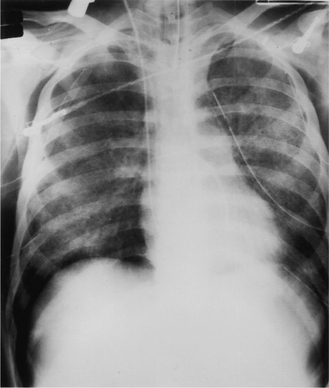
Acute respiratory distress syndrome
Acute respiratory distress syndrome (ARDS) consists of progressive respiratory insufficiency following a major bodily insult and can be due to a large number of factors. Over the years it has been known as ‘shock lung’, ‘stiff lung syndrome’ and ‘adult hyaline membrane disease’.
At the pathophysiological level there is increased permeability of the pulmonary capillaries and the formation of platelet and fibrin microemboli. This results in alveolar oedema and haemorrhage, which can affect the entire lung. After several days, hyaline membranes form within the distal air spaces. As a general rule, symptoms occur on the second day after insult or injury, but the radiograph remains normal during the initial hours of clinical distress. Interstitial oedema is the first radiographic abnormality, which may be of a faint, hazy ground-glass appearance (Fig. 2.23), and this is followed rapidly by patchy air-space oedema. By 36–72 hours after insult, diffuse global air-space consolidation is evident. It is the timing of the radiographic changes relative to the insult and the onset of symptoms, rather than the radiological appearance alone, that suggest the diagnosis of ARDS.
Pneumonia
Pulmonary infection may occur several days after surgery. Pneumonia may complicate collapse but may result from aspiration or inhalation of infected secretions from the pharynx.
The features of consolidation have already been covered but the critically ill or postoperative patient may not show typical appearances of consolidation. Numerous factors, such as prior antibiotic therapy and coexistent heart or lung disease, may alter the radiographic features. The radiographic appearance may vary from a few ill-defined or discrete opacities to a pattern of coalescence and widespread patchy consolidation. Cavity or pneumatocele (a thin-walled air-filled space) formation is not infrequent.
Extrapulmonary air
The diagnosis of a pneumothorax is made by the identification of the thin line of the visceral pleura. Free air may also be found in the pulmonary interstitium, the mediastinum, the pericardial space and the subcutaneous tissues. In the intensive care setting, extrapulmonary air is most often due to barotrauma from mechanical ventilation or secondary to surgery or other iatrogenic procedures. Pulmonary interstitial emphysema is difficult to recognize radiographically and is invariably due to ventilator-induced barotrauma. Unlike air bronchograms, the interstitial air is seen as black lines and streaks radiating from the hila; they do not branch or taper towards the periphery. Interstitial emphysema usually culminates in a pneumomediastinum and this is shown on a frontal radiograph as a radiolucent band against the mediastinum bordered by the reflected mediastinal pleura. Air may outline specific structures such as the aortic arch, the descending aorta or the thymus.
Cardiac failure
The radiographic diagnosis of early left ventricular failure is largely dependent on changes in the calibre of the pulmonary vessels in the erect patient. As the left atrial pressure rises, blood is shunted to the upper zones. This is the first and most important radiographic sign of elevated left ventricular pressure but it is important to remember that, because of redistribution of blood flow in the supine position, a supine radiograph does not allow this criterion to be used.
Interstitial pulmonary oedema then follows; this is manifested by blurring of the vessel margins, a perihilar haze and a vague increased density over the lower zones. When fluid fills and distends the interlobular septa, Kerley B lines (septal lines) may be visible (see Fig. 2.23). These are best visualized in the costophrenic angles as thin white lines arising from the lateral pleural surface. As the left ventricular pressure continues to rise, multiple small, ill-defined opacities occur in the lower half of the lungs. These represent alveoli filling with fluid. Alveolar oedema may also appear as poorly defined bilateral ‘butterfly’ perihilar opacification. Increasing cardiac size usually accompanies cardiac failure but, if it occurs following acute myocardial infarction or an acute arrhythmia, cardiac failure may be present without an increase in cardiac size. Bilateral pleural effusions often accompany cardiac failure.
Pulmonary embolism
The postoperative or critically ill patient has numerous risk factors for the development of deep venous thrombosis and thus pulmonary embolism. In this group, where respiratory distress is often multifactorial, the diagnosis of pulmonary embolism is extremely difficult.
Conventional radiographic findings are non-specific and include elevation of the diaphragm, collapse or segmental consolidation. A small pleural effusion may appear during the first 2 days following the embolus. It is important to recognize that a normal chest radiograph does not exclude a major pulmonary embolus; indeed, a normal radiograph in a patient with acute respiratory distress is suggestive of the diagnosis. A radionuclide perfusion scan is of use because if it is normal a pulmonary embolus can be excluded; however, this is not a practical test for a patient in an intensive care unit and the decision to treat with anticoagulants is often made clinically.
The success of helical CT in the diagnosis of pulmonary embolism relates to its rapid scan time, volumetric data acquisition and high degree of vascular enhancement (see Fig. 2.5).
Kyphoscoliosis
Kyphoscoliosis makes assessment of the chest radiograph difficult and it is useful to reduce the distortion of thoracic contents due to the kyphoscoliosis by obtaining an oblique radiograph, positioning the patient in such a way that the spine appears at its straightest. Severe kyphoscoliosis may cause pulmonary arterial hypertension and cor pulmonale. Some congenital chest anomalies such as pulmonary agenesis (absence of a lung) and neurofibromatosis are associated with dorsal spine abnormalities. Because of the problems associated with getting a true posteroanterior and lateral view, computed tomography scanning is often the most satisfactory method of visualizing the lungs.
Bronchiectasis
Bronchiectasis is a chronic condition characterized by local, irreversible dilatation of the bronchi, usually associated with inflammation. On a chest radiograph (Fig. 2.24A) the findings include:
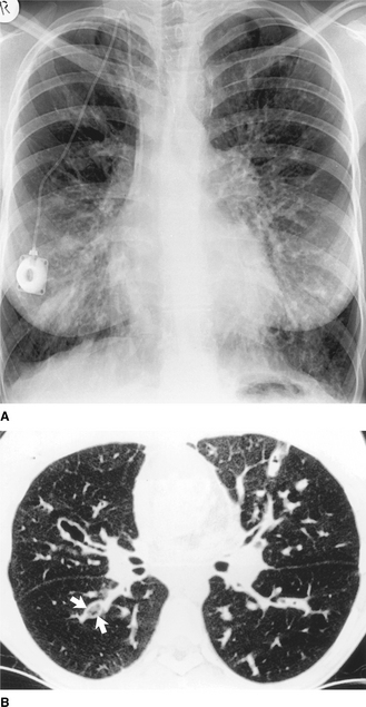
Figure 2.24 Cystic fibrosis. (A) The lungs are overinflated on the PA chest radiograph and there is widespread increased shadowing due to bronchial wall thickening and peribronchial consolidation. Note the prominent central pulmonary artery (pulmonary arterial hypertension may be a complication) and the catheter for long-term intravenous antibiotics. (B) A thin-section CT image of the same patient shows the dilated, bronchiectatic airways, some of which are plugged with mucus (arrows).
 ring and curvilinear opacities which represent thickened airway walls seen end on. These tend to range in size from 8 to 20 mm, have thin (hairline) walls and may contain air–fluid levels dilated airways filled with secretions giving rise to broad-band shadows some 5–10 mm wide and several centimetres long (seen end on, these dilated fluid-filled airways produce rounded or oval nodular opacities) volume loss where bronchiectasis is localized (this may give rise to crowding of bronchi or collapse due to mucus plugging that can be severe and result in complete collapse of a lobe)
The definitive diagnosis of bronchiectasis used to be made by bronchography (injection of contrast into the bronchial airway), but this is an invasive and unpleasant procedure and a viable alternative is high-resolution computed tomography (Fig. 2.24B). With this technique, thin slices are taken throughout both lungs and the findings are similar to those on the plain film (thickened bronchial walls, bronchial dilatation, ring opacities containing air–fluid levels). Comparing the diameter of the bronchial wall with the adjacent vessel is helpful, as both should be approximately the same size. Computed tomography may also be helpful in determining the optimum position for postural drainage. Upper lobe predominance is present in early cystic fibrosis and after tubercle infection and allergic bronchopulmonary aspergillosis. The remaining causes of bronchiectasis (e.g. post-childhood infection) affect predominantly the middle and lower lobes.
Chronic airflow limitation
This comprises three conditions which are present simultaneously in a given patient to a greater or lesser degree: chronic bronchitis, asthma and emphysema. The first is diagnosed by the patient’s history and, strictly speaking, does not have any characteristic radiological features. In asthma the chest radiograph is normal in the majority of patients between attacks, but as many as 40% reveal evidence of hyperinflation during an acute severe episode. In asthmatic children with recurrent infection, bronchial wall thickening occurs. Collapse of a lobe or an entire lung because of mucus plugging is another feature and may be recurrent, affecting different lobes. Complications include pneumomediastinum, which arises secondarily to pulmonary interstitial emphysema and pneumothorax due to rupture of a subpleural bulla. Expiratory radiographs may aid detection of a pneumothorax as well as demonstrating any air trapping secondary to bronchial occlusion.
Emphysema is a condition characterized by an increase in air spaces beyond the terminal bronchiole owing to destruction of alveolar walls. While it is strictly a pathological diagnosis, certain radiographic appearances are characteristic in more advanced cases. These include overinflation of the lungs, an alteration in the appearance of the pulmonary vessels and the presence of bullae. Overinflation results in flattening of the diaphragmatic dome (Fig. 2.25), resulting in an apparently small heart and a decreased cardiothoracic ratio. On the lateral chest radiograph the large retrosternal translu cency caused by the hyperinflated lungs is particularly striking (Fig. 2.25B). The pulmonary vessels are abnormal: the smooth gradation in size of vessels from the hilum outwards is lost, with the hilar vessels being larger than normal and tapering abruptly, so-called ‘pruning’ of the vessels. However, the lungs are usually unevenly involved and this is mirrored by the uneven distribution of pulmonary vessels. When emphysema is predominantly basal in distribution, there is prominent upper lobe blood diversion which should not be mistaken for evidence of left heart failure. Bullae are recognized by their translucency, their hairline walls and a distortion of adjacent pulmonary vessels. They vary greatly in size and are occasionally big enough to occupy an entire hemithorax. When large they are an important cause of respiratory distress. Complications of bullae formation are infection and haemorrhage, which are usually manifested as the presence of an air–fluid level. Pneumothorax is another complication and occasionally may be difficult to distinguish from a large bulla.
PAEDIATRICS
INTRODUCTION
Despite the advent of new imaging modalities, such as ultrasound, computed tomography (CT), magnetic resonance imaging (MRI), ventilation/perfusion lung scans ( scans), positron emission tomography (PET) and CT–PET, the plain chest radiograph remains the mainstay of paediatric chest imaging. In most circumstances the clinical history and examination will be augmented by a chest radiograph before a working diagnosis is made and treatment or further investigations planned.
This section aims to provide a concise and practical introduction to imaging the paediatric chest, emphasizing the importance of the plain chest radiograph but also indicating where other modalities provide additional information or allow the same information to be acquired with less use of ionizing radiation. The first part provides an overview of imaging modalities currently available, the second reviews important radiological signs commonly seen in paediatric chest radiographs and the final part discusses common paediatric chest problems and their radiological signs.
The text has not been referenced extensively but a number of general references and review articles suitable for further reading are given at the end of the chapter.
MODALITIES IN PAEDIATRIC CHEST IMAGING
Plain chest radiographs and fluoroscopy
Chest radiographs may be taken in the erect postero-anterior (PA) or anteroposterior (AP) position or in the supine AP position. In some circumstances, such as on the neonatal unit (NNU) where patient handling is minimized, all films are obtained in the supine AP projection. Up to the age of 3 any of the projections may be used depending on the policy of the department. For patients over the age of 3, most units obtain erect PA films. It is important that within any given unit techniques are standardized and films clearly labelled, as the appearances of some radiological signs, particularly those of pleural fluid and pneumothorax, are profoundly different in the erect and supine positions. These changes will be discussed in greater detail below. Chest radiographs should be obtained in inspiration, using a short exposure time and with attention to technical factors so as to minimize the radiation exposure to the patient and attendants.
The lateral chest radiograph necessitates a significantly higher exposure than the frontal and is not required routinely. It is usually obtained during the follow-up of patients with malignant disease likely to metastasize to the chest and sometimes in the assessment of recurrent chest infections and cystic fibrosis. A lateral view may also be performed to clarify an abnormality seen on the frontal projection.
Coned, AP plain radiographs using a high kVp technique and filtration to give an optimal exposure are used to demonstrate the anatomy and calibre of the major airways.
One of the disadvantages of conventional radiographs is that it is difficult to adequately demonstrate all soft tissue and bony structures using the same exposure factors. Two major developments have attempted to overcome these disadvantages. The first is digital chest radiography, in which a phosphor plate is used for the exposure. The plate is then scanned with a laser beam, which reads the information and stores it in digital form. The information can then be reconstructed as the ‘chest X-ray’ on a computer screen and manipulated to allow optimal visualization of areas of interest. Hard copies of the images can be printed on a laser imager. The advantages of this technique in paediatric radiology are the uniformity of image that can be maintained from day to day, the facility for image manipulation and a reduction in radiation dose.
The second technique, scanning equalization radiography (SER), uses a beam of X-rays to scan the patient. The exposure is continuously changing according to the tissues within the beam at any given time. This results in a more even exposure and a more uniform image.
Fluoroscopy remains a useful technique for assessing diaphragmatic movements.
Bronchography and tomography
Since CT and MRI have become widely available, conventional tomography is no longer used. Bronchography is rarely undertaken to demonstrate focal bronchial narrowing; such cases are now investigated using multi-slice CT scans with three-dimensional reconstructions and virtual bronchoscopy software.
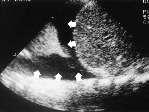
Ultrasound
Ultrasound is useful for examining the pleural space for fluid (Fig. 2.26). Effusions and empyemas can be located, measured and drained under ultrasound control. Because the ultrasound beam is strongly reflected by aerated lung, ultrasound is less useful for assessing lung lesions unless they are peripheral, lie against the chest wall and consist of either solid or fluid. The movement and integrity of the hemidiaphragms can be assessed using ultrasound. The disadvantage is that each hemidiaphragm can only be assessed independently and not in relationship to each other. This is important in mild hemidiaphragm paresis. Cardiac ultrasound is an extremely accurate non-invasive way of assessing congenital heart disease.
Computed tomography and magnetic resonance imaging
In many ways these techniques are complementary and will be discussed together. Both techniques require the patient to remain still for the duration of the scan and this is particularly important in MRI. Neonates and young infants may be examined if asleep after a feed, but older infants and children usually require sedation or general anaesthesia.
Computed tomography and high-resolution computed tomography
CT uses a narrow beam of X-rays to image the patient in ‘slices’. The thickness of the slice may be varied from 1.5 mm to 1 cm and slices may be taken with or without gaps between them, depending on the region being examined and the likely pathology. Modern multislice scanners are very fast and allow the whole chest to be scanned in one breath hold. Assessment of the mediastinum and of vascular structures is facilitated by using intravascular contrast medium.
Lung pathology is best evaluated on CT, using high-resolution computed tomography (HRCT) if necessary. HRCT uses a thin slice thickness and special software to demonstrate the lung parenchyma. HRCT is used in the diagnosis of diffuse parenchymal disease and bronchiectasis.
CT has better spatial resolution and can detect fine calcification, which affords it an advantage over MRI in evaluating mediastinal masses and lymphadenopathy. Bone structure, and in particular cortical change, are better imaged on CT.
Vascular structures are well demonstrated on CT if an intravascular contrast agent containing iodine is used. Fast multislice CT scanners, which enable the entire chest to be scanned in a matter of seconds, facilitate the investigation of congenital vascular and cardiac abnormalities.
Magnetic resonance imaging
In MRI the patient lies within a strong magnetic field and is exposed to pulses of radiofrequency energy. This energy is absorbed by protons within the body. When the radiofrequency pulses are stopped, the protons return to their normal state but as they do they release energy, the magnetic resonance signal, which can be detected by coils placed around the body. Magnetic resonance signals are different for different tissues and may be altered by disease. Intravascular contrast medium for MRI is available.
MRI of the chest is complicated by cardiac and respiratory movements. These effects can be minimized by only taking images at the same point in each cardiac and respiratory cycle, a technique known as gating.
MRI has three major advantages over CT: its superior soft tissue contrast, its ability to acquire images in any plane and the fact that it does not use ionizing radiation. Sagittal, coronal and oblique images are of immense value in assessing mediastinal masses and in evaluating whether a paraspinal mass extends into the spinal canal.
One of the most exciting branches of MRI is magnetic resonance angiography (MRA), which allows blood vessels and the heart to be imaged without the need for arterial puncture. Optimal MRA images are obtained after intravenous injection of a contrast agent containing gadolinium and using oblique scan planes.
Angiography and cardiac catheterization
Cardiac ultrasound and MRI/MRA have reduced the need for diagnostic conventional angiography and cardiac catheterization to assess congenital anomalies of the aorta and pulmonary vessels and congenital arteriovenous malformations. Most conventional angiography or cardiac catheterization is now performed as part of a therapeutic interventional procedure.
Barium studies
These studies have a limited but very important place in the assessment of chest problems, specifically the barium swallow to evaluate extrinsic oesophageal compression by aberrant vessels or masses and the swallow/meal to assess intrinsic abnormalities such as uncoordinated swallowing, abnormal oesophageal peristalsis or gastro-oesophageal reflux that can cause aspiration. If a tracheo-oesophageal fistula is suspected, a tube oesophagram must be performed in the prone position.
There is no reliable technique for the positive diagnosis of aspiration; this includes the barium swallow/meal as well as the isotope milk scan. Recurrent aspiration may be inferred when there is severe gastro-oesophageal reflux.
Radionuclide studies
Radionuclide studies provide quantifiable functional information which complements the anatomical information provided by other imaging modalities. The ventilation/perfusion scan ( scan) uses krypton (81mKr) gas for ventilation and technetium (99mTc) labelled macroaggregates for perfusion. The scan is the only method which will provide information on regional lung function. The radiation burden from the  scan is less than one-fifth of a chest radiograph while the
  scan has a dose equal to less than 60 seconds of fluoroscopy.
Most ventilatory disturbances result in a corresponding reduction in perfusion whereas if the pulmonary artery to a region is occluded (pulmonary embolus, sequestrated segment or pulmonary artery disease) that region remains ventilated. Occasionally other radionuclide studies such as bone scans or milk scans are indicated in the assessment of chest pathology.
Positron emission tomography and computed tomography–positron emission tomography
Positron emission tomography (PET) is a functional nuclear medicine technique that uses radioactive isotopes that have a short half-life and decay by emitting a positron. The emitted positrons collide with surrounding electrons producing a pair of photons, which can be detected by the scanner. The isotope most commonly used is 18F and this is incorporated with glucose to form the tracer [18F]fluorodeoxyglucose (FDG). Many malignant tumours have an altered glucose metabolism that results in FDG accumulating within their cells; this increased uptake allows them to be detected.
PET provides good information on tumour activity but very poor anatomical information on the location of the tumour, whereas CT provides excellent anatomical information but no functional information. The hybrid CT–PET scanners perform both scans and integrate the information to provide information on tumour activity (PET) superimposed on the fine anatomical CT images.
In paediatric chest imaging, PET and CT–PET have been used to stage and monitor malignant disease, particularly Hodgkin’s lymphoma, bone sarcoma and neuroblastoma. Nonetheless their exact place in the management of these and other paediatric malignancies has yet to be determined.
Radiation and patient safety
Neonates, infants and children are more susceptible to the harmful effects of ionizing radiation than adults and their exposure to it should be kept to a minimum. Exposure can be minimized by using techniques like ultrasound and MRI, which do not use ionizing radiation, whenever possible. If plain radiographs are needed the dose can be minimized by using optimal radiographic techniques and modern dose-reducing equipment. High-dose investigations such as nuclear medicine studies, CT and CT–PET should be performed only after careful consideration of the potential benefits of the investigation weighed against the potential risks. This benefit–risk analysis may be best undertaken within a multidisciplinary team where the viewpoints of patient, parents and all of the professional groups involved in the patient’s care can be considered.
BASIC SIGNS ON THE PLAIN CHEST RADIOGRAPH
Consolidation
Replacement of air in the very distal airways and alveoli by fluid or solid is called consolidation. The cardinal signs of consolidation are an area of increased opacity, which may have an irregular shape, irregular margins, a non-segmental distribution and contains an air bronchogram (Fig. 2.27). The volume of the affected lung remains unchanged and consequently there are no signs of loss of volume. If an area of consolidation abuts the mediastinum, heart or diaphragm their clear silhouette, which is dependent upon the sharp radiological contrast between normally aerated lung (black) and solid structures (white), is lost (Fig. 2.27). Similarly the presence of air bronchograms within an area of consolidation can be explained by the sharp contrast between air in the medium and large bronchi (black) and the surrounding non-aerated and ‘solid’ lung (white) (Figs 2.27, 2.28).
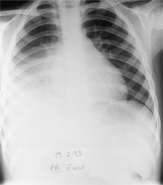
Figure 2.27 Right lower lobe consolidation caused by the bacterium Streptococcus pneumoniae. There is increased opacity in the right lower and mid zones, loss of the clear outline of the right hemidiaphragm and a proximal air bronchogram.
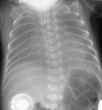
Figure 2.28 Anteroposterior (AP) supine radiograph of a premature neonate with respiratory distress syndrome (RDS). The lungs show generalized opacity due to consolidation and a prominent air bronchogram.
A variant of infective consolidation frequently seen in infants and children is the ‘round pneumonia’. This may mimic a mass lesion radiologically since it has well-defined borders, but the clinical picture points to an infective aetiology. While infection is the most common cause, consolidation is also caused by any pathological process in which the alveoli are filled by fluid or solid. The most common causes of consolidation in paediatric practice are listed in Box 2.3.
Collapse
In collapse, air within the alveoli and distal airways is absorbed, resulting in loss of lung volume. This may affect a lung, lobe or segment. This is manifest on the radiograph by shift of the normal fissures and crowding of airways in the collapsed lung (Figs. 2.29, 2.30). If the volume loss is large there may also be mediastinal shift towards the affected side, elevation of the ipsilateral hemidiaphragm, ipsilateral rib crowding and alteration in hilar position. The collapsed lobe may or may not cause increased radio-opacity and there may be compensatory hyperinflation of unaffected lobes. If the collapsed lobe abuts on part of the diaphragm or cardiomediastinal silhouette, the clear outline of these may be lost on the radiograph, as in consolidation (Figs 2.29, 2.30). Collapse is most often due to obstruction of a large airway by foreign body, mucus plug, tumour or extrinsic compression. Less commonly it occurs secondary to poor ventilation.
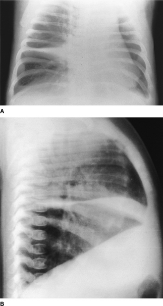
Figure 2.29 (A) Anteroposterior (AP) radiograph taken in a lordotic projection to show the band-like opacity of middle lobe collapse. Part of the right heart silhouette is lost where the collapsed lobe abuts the heart. (B) Lateral radiograph showing the collapsed middle lobe and displaced fissures. In addition, the lungs show generalized overinflation with some flattening of the diaphragm.
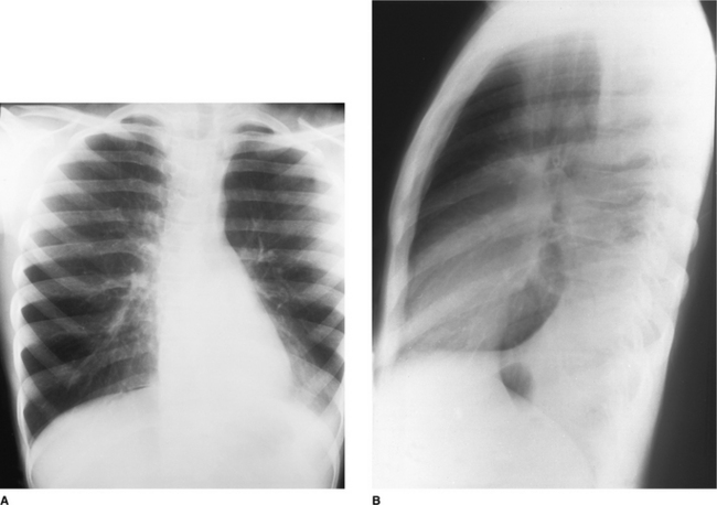
Figure 2.30 (A) Frontal radiograph of a patient with asthma and a left lower lobe collapse caused by a mucus plug. Generalized overinflation, increased opacity in the left cardiac region and loss of clarity of the outline of the medial left hemidiaphragm. (B) The lateral radiograph shows the collapsed left lower lobe as a wedge-shaped opacity in the lower chest posteriorly.
Pleural fluid
The radiological appearance of pleural fluid is largely determined by the position of the patient. In the erect position the fluid collects at the bases and initially causes blunting of the costophrenic angles. Larger effusions cause a homogeneous opacity with a concave upper border higher laterally than medially – the meniscus. Very large effusions may cause mediastinal shift to the opposite side.
In the supine position, often used for neonatal and infant radiographs, an effusion causes reduced transradiancy (whiter hemithorax) of the affected side and may collect around the apex of the lung. In larger effusions a peripheral band of soft tissue density appears between the chest wall and the lung; on the right this band has a characteristic step at the position of the horizontal fissure (Figs 2.26, 2.31). Pleural fluid may collect and loculate within fissures or between the inferior surface of the lung and the diaphragm, the ‘subpulmonic’ effusion.
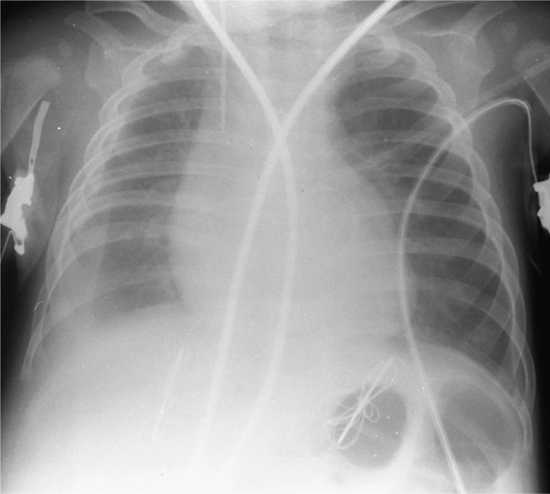
Pneumothorax
In the erect position pleural air collects at the apex, causing increased apical transradiancy (darker apex) and absent lung markings beyond a visible lung edge. In the supine position air collects initially in the anteroinferior chest, causing quite different and often subtle signs. These include small slivers of air at the apex, around the heart and between the lung and the diaphragm. Where free air as opposed to aerated lung abuts part of the cardiomediastinal or diaphragmatic silhouette, the clarity of that border is especially sharp, this being the opposite of the effect seen in consolidation. A large pneumothorax in neonates and infants when supine may collect anteriorly and cause an increased ipsilateral transradiancy (darker hemithorax) and increased sharpness of the cardiomediastinal silhouette (Fig. 2.32).
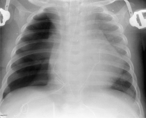
Figure 2.32 Supine radiograph showing a postoperative right pneumothorax. There is increased transradiancy of the right hemithorax. The right heart border is very clearly defined and the right lung edge is visible.
A tension pneumothorax occurs when a pleural tear acts as a one-way flap valve, allowing air into the pleural space but preventing egress. The pressure within the hemithorax rises and may remain positive for much of the respiratory cycle, causing mediastinal shift to the contralateral side and flattening, or even eversion, of the ipsilateral hemidiaphragm (Fig. 2.33).
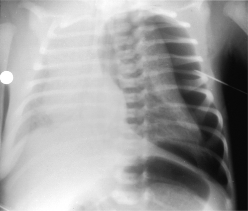
COMMON PAEDIATRIC CHEST PROBLEMS
Congenital abnormalities of the chest
Congenital diaphragmatic hernia
Large congenital diaphragmatic hernias frequently present as neonatal respiratory distress although many are now diagnosed antenatally on routine antenatal ultrasound examination. Many are associated with other congenital anomalies. Most hernias are left-sided, situated posteriorly and large. Abdominal organs are sited in the chest and appear on the radiograph as a cystic/solid mass. The mediastinum is shifted to the contralateral side and one or both lungs may be hypoplastic (Fig. 2.34). When large, the condition carries a high mortality.
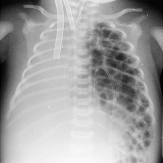
Hiatus hernia
A sliding hiatus hernia exists when the lower oesophageal sphincter and part of the stomach are situated in the thorax, above the diaphragm. This condition is usually associated with incompetence of the sphincter and may result in feeding problems, gastro-oesophageal reflux and aspiration. Gastro-oesophageal reflux may trigger episodes of reactive wheezing or of asthma. These episodes may be caused by microaspiration or be vagally mediated.
Congenital lobar emphysema
A focal abnormality of a lobar bronchus leads to a ball valve effect, causing air trapping and overinflation of the affected lobe. The left upper, right middle and right upper lobes are most frequently affected. Initial radiographs in the first few hours of life may show an opaque mass in the region of the affected lobe. As fluid clears, the appearances are those of an overinflated lobe with compression of normal surrounding lung and mediastinal shift to the contralateral side (Fig. 2.35). Treatment is surgical excision of the affected lobe if the neonate is in respiratory distress; if found in the older infant, conservative management is advocated.
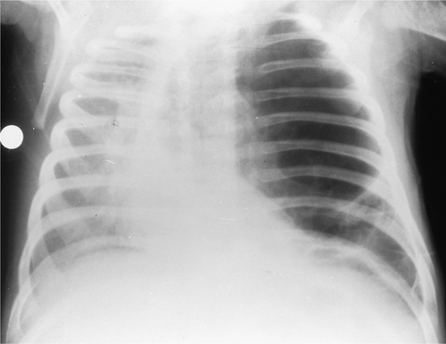
Congenital cystic adenomatoid malformation
This condition, caused by a disorganized and usually cystic mass of pulmonary tissue, can mimic both congenital diaphragmatic hernia and congenital lobar emphysema. The hamartomatous mass can affect any lobe, although the middle lobe is rarely affected, and in one-fifth of cases more than one lobe is affected. The radiograph shows a well-defined cystic mass, which may be large, compress adjacent lung and cause mediastinal shift.
Neonatal chest problems
Respiratory distress syndrome
Immature surfactant production in premature infants, infants of diabetic mothers and infants who experience perinatal asphyxia fail to reduce the alveolar surface tension sufficiently to prevent alveolar collapse. This is the most common cause of respiratory distress in premature neonates and causes tachypnoea, cyanosis, expiratory grunting and chest wall retraction. The radiograph shows bilateral symmetrical hypo-aeration, small volume lungs, ground-glass granularity of the pulmonary parenchyma and well-defined air bronchograms extending from the hilum into the peripheral lung (see Fig. 2.28).
These neonates frequently require intermittent positive pressure ventilation which may give rise to specific complications of pulmonary interstitial emphysema (PIE) (Fig. 2.36), bronchopulmonary dysplasia (BPD) (Fig. 2.37), pneumothorax (Fig. 2.32) and pneumomediastinum.
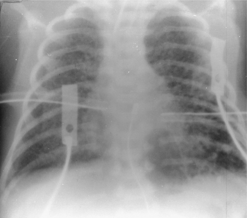
Figure 2.36 Pulmonary interstitial emphysema (PIE) complicating respiratory distress syndrome (RDS). There is a branching pattern of gas with associated small bubbles. Bilateral chest drains and persistent right pneumothorax.
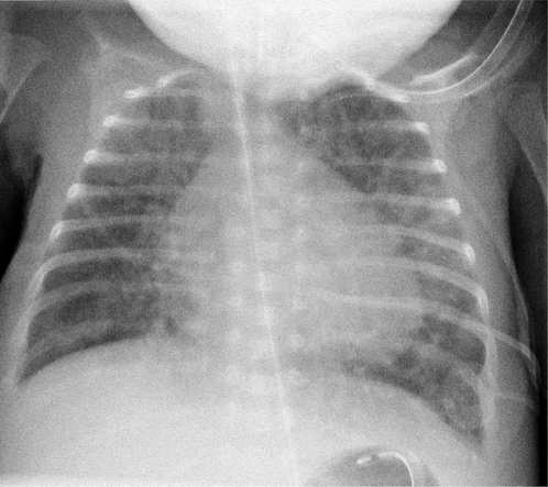
Pulmonary interstitial emphysema is caused by gas leaking from overdistended alveoli and tracking along bronchovascular sheaths. The radiographic appearance is that of a branching pattern of gas with associated bubbles affecting all or part of the lung (see Fig. 2.36).
Bronchopulmonary dysplasia or chronic lung disease of prematurity (CLD) is seen exclusively in infants who have been on positive pressure ventilation, usually for RDS. The combination of high-pressure trauma and oxygen toxicity results in lung damage. The lung may pass through a number of radiological stages during the evolution of BPD. Initially there is an RDS pattern which progresses to almost complete opacification and then to a coarse pattern of linear opacities and cystic lucencies (Fig. 2.37). The lack of adequate oxygenation in RDS may result in failure of the ductus arteriosus to close. The consequent left-to-right shunt may progress to frank plethora and heart failure.
Meconium aspiration syndrome
This is the most common cause of respiratory distress in full- or post-term neonates. The aspirated meconium causes a chemical pneumonitis and bronchial obstruction. The radiographic picture is of bilateral diffuse patchy collapse with other areas of overinflation (Fig. 2.38). Spontaneous pneumothorax, pneumomediastinum and small effusions are common but air bronchograms are rare.
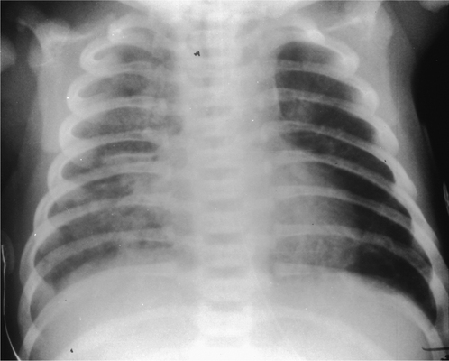
Respiratory tract infections
Viral infections
Viral infections generally affect the bronchi and peribronchial tissues and this is reflected in the radiological signs: symmetrical parahilar, peribronchial streaky shadowing radiating for a variable distance into the lung periphery, hilar lymphadenopathy, occasionally reticulonodular shadowing, segmental/lobar collapse and generalized overinflation secondary to narrowing of the bronchi (Fig. 2.39). Effusions are rare. Organisms commonly encountered are the respiratory syncytial virus (RSV), influenza and parainfluenza viruses, adenovirus and rhinovirus.
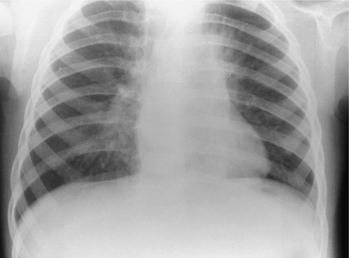
Bacterial and Mycoplasma infections
In the neonatal period the most common organisms are non-haemolytic streptococci, Staphylococcus aureus and Escherichia coli. Lobar consolidation is rare and more often the following signs are seen: radiating perihilar streakiness, coarse patchy parenchymal infiltrates, nodular or reticulonodular shadowing, or diffuse hazy shadowing, most often basal. One important pattern to recognize is the diffuse bilateral granularity of group B haemolytic streptococcal pneumonia, which so closely mimics RDS.
In infants bacterial infection is more often seen as lobar or patchy consolidations (Fig. 2.27). The organisms are most commonly Haemophilus influenzae, Streptococcus pneumoniae, Staphylococcus aureus and Mycoplasma pneumoniae. Pleural effusions, empyemas, abscesses and pneumatoceles are well-recognized complications. The ‘round pneumonia’ is an area of infective consolidation which transiently has a rounded configuration and mimics a mass lesion. Mycoplasma pneumoniae infection can mimic the radiographic appearances of both bacterial and viral pneumonia. However, one pattern that is highly specific is unilobar reticulonodular infiltration, especially if associated with hilar lymphadenopathy and a small pleural effusion.
Tuberculosis
Tuberculosis acquired in infancy is usually manifest by unilateral hilar or paratracheal lymphadenopathy and occasionally the primary or Ghon focus is seen as an area of consolidation in the periphery of the ipsilateral lung (Fig. 2.40). Collapse is seen, usually due to compression of a bronchus by lymph nodes. Bronchopneumonic spread, with widespread areas of consolidation, occurs if either an infected node discharges into a bronchus or when host resistance is very low, facilitating spread through the airways. Miliary tuberculosis, with multiple small nodules, is caused by the haematogenous spread that occurs when an infected node discharges into the bloodstream. Cavitation is unusual in children.
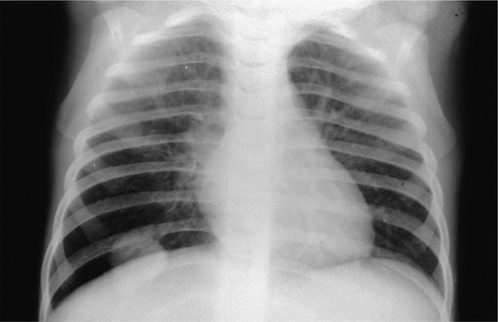
Airway disease
Asthma
The radiological features are rarely seen before the age of 3 years. In chronic asthma there is generalized overinflation of the lungs with parahilar, peribronchial infiltrates but hilar lymphadenopathy is rare. Plugs of viscid mucus obstruct the airways and cause recurrent segmental or lobar collapse (Fig. 2.30). Pneumomediastinum is a common complication but rarely requires specific treatment; pneumothorax is seen less frequently. Asthma may be triggered by gastro-oesophageal reflux and barium studies may be useful in assessing the patient.
Obstruction by foreign bodies
Aspirated foreign bodies most commonly lodge in the major bronchi and act like a ball valve, causing a distal obstructive emphysema (Fig. 2.41). Radiographs are taken in inspiration and expiration to demonstrate the air trapping. Less commonly, the lung distal to the obstruction collapses and may become infected.
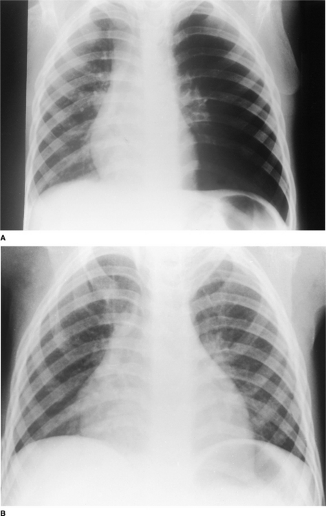
Cystic fibrosis and bronchiectasis
This autosomal recessive condition causes excessively thick and viscid mucus. In the neonatal period, bowel obstruction due to meconium ileus may draw attention to the condition. In the chest the earliest signs are very similar to those of viral bronchiolitis: overinflation, focal collapse and parahilar, peribronchial infiltrates (Fig. 2.42). Recurrent infections lead to bronchiectasis, fibrosis and generalized overinflation with segmental areas of collapse. Bronchial collaterals are recruited and when these become large, haemoptysis may be a problem. HRCT is more accurate than radiographs in demonstrating early bronchiectasis and the involvement of small airways.
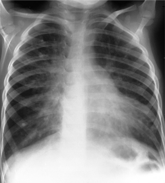
Figure 2.42 Cystic fibrosis: overinflation, focal collapse and parahilar, peribronchial infiltrates.
CT is also useful in identifying and accurately positioning small pneumothoraces facilitating accurate drainage.
Small airway disease
Inflammatory disease of the smaller airways is common and may occur following viral infection and as part of other conditions, including cystic fibrosis, asthma, recurrent aspiration, post-transplantation and post- chemotherapy. Inflammatory tissue narrows and obstructs the airways causing air trapping. Plain radiograph changes are variable and often underestimate the extent of the disease. Constrictive obliterative bronchiolitis (bronchiolitis obliterans) is best assessed using HRCT. The combination of areas of air trapping and inhomogeneous perfusion gives rise to the mosaic attenuation pattern with a mixed pattern of high- and low-density areas in the lung parenchyma. There may be associated abnormalities of the larger airways.
Swyer–James or Macleod’s syndrome is an unusual form of post-infection constrictive obliterative bronchiolitis in which the lung changes are unilateral. In these cases the plain radiograph may show the characteristic feature of unilateral hypertransradiancy caused by air trapping.
Acknowledgements
I wish to acknowledge the huge contribution made to the paediatric section by Professor Isky Gordon of Great Ormond Street Hospital for Sick Children, an inspiring teacher and mentor who co-authored previous editions of this chapter. I also wish to thank Dr BJ Loveday at the Royal Surrey County Hospital, Guildford, and Dr DB Reiff at Ashford and St Peter’s Hospital, for allowing us to use their radiographs as illustrations and Mrs Hazel Cook, Mrs Mary Shoesmith and Mrs Susan Ranson of the Department of Diagnostic Radiology at the Royal Surrey County Hospital, Guildford, and the Department of Medical Illustration at Great Ormond Street Hospital for Children, for their help in preparing the illustrations.
Arthur R. The neonatal chest X-ray. Paediatric Respiratory Reviews. 2001;2:311-323.
Copley SJ. Application of computed tomography in childhood respiratory infections. British Medical Bulletin. 2002;61:263-279.
Copley SJ, Bush A. HRCT of paediatric lung disease. Paediatric Respiratory Reviews. 2000;1:141-147.
De Bruyn R. Paediatric chest. In: Cosgrove D, Meire H, Dewbury K, editors. Clinical ultrasound: abdominal and general ultrasound. London: Churchill Livingstone; 1993:983-988. 2
Frush DP. Paediatric chest imaging. Radiologic Clinics of North America. 2005;43:253-457.
Gibson AT, Steiner GM. Imaging the neonatal chest. Clinical Radiology. 1997;52:172-186.
Goodman LR. Felson’s principles of chest roentgenology: a programmed text, 2nd edn., Philadelphia: WB Saunders, 1999.
Goodman LR, Putman CE. Intensive care radiology: imaging of the critically ill, 3rd edn., Philadelphia: WB Saunders, 1991.
Gordon I, Helms P, Fazio F. Clinical applications of radionuclide lung scanning. British Journal of Radiology. 1981;54:576-585.
Gordon I, Matthew DJ, Dinwiddie R. Respiratory system. In: Gordon I, editor. Diagnostic imaging in paediatrics. London: Chapman and Hall; 1987:27-57.
Grainger RG, Allison DJ, Dixon AK. Grainger and Allison’s diagnostic radiology. A textbook of medical imaging. 4th edn. Edinburgh: Churchill Livingstone; 2001.
Hansell DM, Armstrong P, Lynch DA, McAdams HP. Imaging of diseases of the chest, 4th edn., London: Elsevier Mosby, 2005.
Hayden CK, Swischuk LE, editors. Pediatric ultrasonography, 2nd edn., Baltimore: Williams and Wilkins, 1992.
Heitzmann ER. The mediastinum: radiologic correlations with anatomy and pathology, 2nd edn., Berlin: Springer-Verlag, 1988.
Hendry GMA. Magnetic resonance imaging of the paediatric chest. Pae-diatric Respiratory Reviews. 2000;1:249-258.
Keats TE, Anderson MW. Atlas of normal roentgen variants that may simulate disease, 7th edn., St Louis: Mosby, 2001.
Kim OH, Kim WS, Kim MJ, et al. US (ultrasound) in the diagnosis of pediatric chest diseases. RadioGraphics. 2000;20:653-671.
Lipscombe DJ, Flower CDR, Hadfield JW. Ultrasound of the pleura: an assessment of its clinical value. Clinical Radiology. 1981;32:289-290.
Newman B. The pediatric chest. Radiologic Clinics of North America.. 1993;31:453-719.
Piepsz A, Gordon I, Hahn K. Paediatric nuclear medicine. European Journal of Nuclear Medicine. 1991;18:41-66.
Reed JC. Chest radiology: plain film patterns and differential diagnoses, 5th edn., St Louis: Mosby, 2003.
Rossi UG, Owens CM. The radiology of chronic lung disease in children. Archives of Disease in Childhood. 2005;90:601-607.
Simon G. The anterior view chest radiograph - criteria for normality derived from a basic analysis of the shadows. Clinical Radiology. 1975;26:429-437.
Swischuk LE. Imaging of the newborn, infant and young child, 3rd edn., Baltimore: Williams and Wilkins, 1989.
Vix VA, Klatte EC. The lateral chest radiograph in the diagnosis of hilar and mediastinal masses. Radiology. 1970;96:307-316.
Webb RW, Müller NL, Naidich DP. High-resolution CT of the lung, 3rd edn., Philadelphia: Lippincott Williams & Wilkins, 2001.