Page 107 

8 Vertebral Column

  Page 108 

CERVICAL SPINE

image

Projection: AP C1–C3

Centring Point: To the lower border of the incisors – directly to the open mouth

image

Projection: AP C3–C7

Centring Point: To the sternal notch – then angle the central ray cranially to the thyroid cartilage. Central ray approximately 15° cranially

Points to consider

Technique

image Remember to set the exposure before positioning

image Remember to remove jewelry that is in the field of interest and dentures/orthodontic appliances where possible

image 
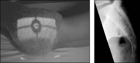
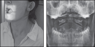
AP C1–C3 – adjust patient so that occipital bone and lower edge of upper incisors are superimposed

image AP C1–C3 – patient may overextend the head when opening the mouth

image AP – mental region of mandible should be superimposed over the occiput

image
  Page 109 

Radiological assessment

image Check that each intervertebral joint space is consistent

image AP C1–C3 – the odontoid process must be clear of the occipital bone

image All vertebral bodies should be rectangular – any variation may be due to trauma

image AP – ensure C3–T1 are visualised – C1–C3 may be obscured

AP C1–C3

Patient erect or supine

Median sagittal plane 90° to the cassette

Patient’s neck is extended until the upper occlusal plane is perpendicular to the table top

The patient is then asked to open the mouth as wide as possible, ensure the occlusal plane remains perpendicular to the table top

Collimation

To include: SUPERIORLY: Upper C1

INFERIORLY: Body C3

LATERALLY: Transverse processes

AP C3–C7

Patient erect or supine

Median sagittal plane 90° to the cassette

Patient’s neck is extended until the angle of the mouth and the tragus of the ear are perpendicular to the table top

Collimation

To include: SUPERIORLY: Lower border of mandible

INFERIORLY: Body T1

LATERALLY: Transverse processes

  Page 110 

CERVICAL SPINE

image

Projection: LATERAL

Centring Point: 2.5 cm behind and 5 cm below the angle of the mandible

image

Projection: ANTERIOR OBLIQUES

Centring Point: To the middle of the cervical spine. Central ray 15° caudal

Points to consider

Technique

image Acute trauma – use horizontal beam – do not adjust head

image Remember to remove jewelry/ear-rings that is in the field of interest

image Exposure made on arrested expiration

image Must include C7 on the radiograph

image Oblique – extend the head back to avoid superimposition of the mandible

image
  Page 111 

Radiological assessment

image 
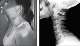
Anterior displacement over 3.5 mm – ligaments torn

image Vertebral bodies C3–T1 should be the same size – a disparity of 2 mm may be due to a compression #

image Check all seven vertebrae are seen on the radiograph

image Oblique – demonstrates intervertebral foramina closest to the film (right anterior oblique – right foramina; left anterior oblique – left foramina)
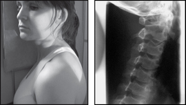
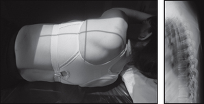
Lateral

Patient in the erect position with the shoulder against the cassette

Median sagittal plane parallel to the cassette

Patient’s shoulders should be relaxed and arms are placed down and slightly behind the trunk

Feet are separated to aid stability

Patient’s chin is raised and extended slightly forwards so that the mandible does not obscure the spine

Collimation

To include: SUPERIORLY: EAM

INFERIORLY: Body T1

LATERALLY: Soft tissue borders

Anterior obliques – both sides for comparison
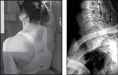
Patient erect facing a vertical bucky

Trunk is then rotated 45° to each side in turn

Patient’s head is rotated so that the median sagittal plane is parallel to the bucky

As with every x-ray ensure anatomical legends are applied as interpretation without them at times can be confusing

Collimation

To include: SUPERIORLY: EAM

INFERIORLY: Body T1

LATERALLY: Soft tissue borders

  Page 112 

CERVICOTHORACIC

image

Projection: SWIMMER’s

Centring Point: To a level just above the shoulder remote from the cassette. Horizontal central ray

Points to consider

Technique

image Remember to set the exposure before positioning

image Exposure must penetrate the shoulder region

image Do not rotate the thorax unless an oblique projection is required

image Exposure on arrested respiration

Radiological assessment

image Check that each intervertebral joint space is consistent

image Shoulders should be seen separated from each other

image All vertebral bodies should be rectangular – any variation may be due to trauma

image Must include from C5 to T5

Swimmer’s

Patient erect

Shoulder is placed against the erect bucky

  Page 113 

Arm nearest the cassette is raised and folded over the head

Arm furthest from the cassette is depressed as far as possible

Median sagittal plane is parallel to the cassette

image

Collimation

To include: SUPERIORLY: Body C5

INFERIORLY: Body T5

ANTERIORLY: Anterior clavicles

POSTERIORLY: Posterior ribs

  Page 114 

THORACIC SPINE

image

Projection: AP

Centring Point: To a point 5 cm below the suprasternal notch

image

Projection: LATERAL

Centring Point: To a point 5 cm anterior to the palpable sixth spinous process

Points to consider

Technique

image AP – use a wedge filter to prevent the upper thoracic vertebrae being over-penetrated

image Flex the knees to aid the patient’s comfort

image AP – exposure on arrested inspiration

image Lateral – a long exposure with gentle breathing to blur the lung fields and ribs (diffusion technique)

image
  Page 115 

Radiological assessment

image 
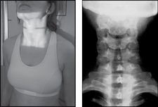
AP – abnormal soft tissue enlargement around the spine is a positive indication of trauma or infection

image Check all pedicles are present and intact

image Vertebral bodies should be the same height – anteriorly and posteriorly

image Lateral – upper spine difficult to visualise due to shoulders. A swimmer’s projection may be required – CT is better
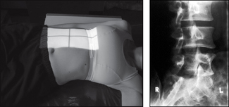
AP

Patient supine

Median sagittal plane perpendicular to the cassette

A small pillow supports the head

Patient’s arms are placed down by the side

Collimation

To include: SUPERIORLY: Body of C7

INFERIORLY: Body of L1

LATERALLY: Transverse processes and soft tissues

Lateral

Patient lying on their side

Median sagittal plane and the spine are parallel to the table top

Arms are raised and placed onto the pillow

Knees are flexed and a soft pad is placed between them for comfort

Collimation

To include: SUPERIORLY: Upper thoracic spine

INFERIORLY: Body of L1

ANTERIORLY: Vertebral bodies

POSTERIORLY: Posterior rib cage

  Page 116 

LUMBAR SPINE

image

Projection: AP

Centring Point: Midline at the level of lower costal margin

image

Projection: LATERAL

Centring Point: 8–10 cm anterior to the third lumbar spinous process at the level of the lower costal margin

Points to consider

Technique

image 
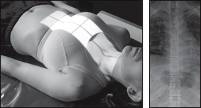
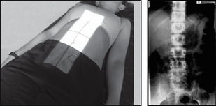
AP – reduce lumbar lordosis – flex knees and support where indicated

image AP – ensure sacroiliac joints included on the radiograph

image AP and lateral – exposure on arrested expiration – diaphragm should be above L1 – or try breathing technique to blur bowel shadows

image 
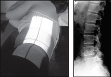
Lateral – non-opaque pad under the waist may assist in bringing the spine parallel to the table top

image Use gonad shield – but take care not to obscure the area of interest

image
  Page 117 

Radiological assessment

image AP – distance between pedicles gradually widens from L1 to L5

image AP – must inspect the transverse processes for #

image Check soft tissue changes – may indicate underlying pathology – renal stones mimic skeletal back pain

image Lateral – vertebral bodies should be same height anteriorly and posteriorly

image Any loss of height or wedging suggests a possible compression #

AP

Patient supine

Median sagittal plane perpendicular to the table top and the anterior superior iliac spines (ASIS) are equidistant

Hips and knees are flexed and where indicated supported with pads

Patient’s arms are placed across the upper thorax or away from the body

Collimation

To include: SUPERIORLY: T12

INFERIORLY: Sacroiliac joints

(Some imaging centres require visualisation of the kidneys due to the possibility of referred pain from kidney pathology)

LATERALLY: Sacroiliac joints

Lateral

Patient lying on side

Median sagittal plane and the spine are parallel to the table top

Arms are raised and placed onto the pillow

Knees are flexed and a soft pad may be placed between them for comfort

Collimation

To include: SUPERIORLY: T12

INFERIORLY: L5 – sacral junction

ANTERIORLY: Vertebral bodies (possibly kidneys)

POSTERIORLY: Spinous processes

  Page 118 

LUMBAR SPINE

image

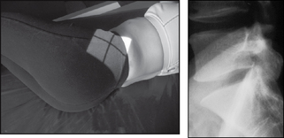
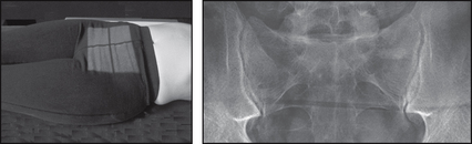
Projection: LUMBOSACRAL JUNCTION (L5–S1)

Centring Point: 8 cm anterior to the fifth lumbar spinous process

image

Projection: AP OBLIQUES

Centring Point: To the mid-clavicular line on the raised side at the level of lower costal margin

Points to consider

Technique

image Do not proceed until you have examined the lateral

image L5–S1 – a 5° caudal angulation may open the disc space

image L5–S1 – collimation important to reduce scattered radiation

image Lateral – place a non-opaque pad under the waist to bring the spine parallel to the table top

image

Radiological assessment

image Disc space at L5–S1 – usually smaller than at L4–L5

image Joint space must be visualised open

image Obliques – suspected spondylolisthesis – a defect in pars articularis – look for a collar around the Scottie dog’s neck!

image Obliques – will demonstrate superior and inferior articular processes and the zygopophyseal joints of the side nearest the cassette

Lumbosacral junction (L5–S1)

Patient lying on side

Median sagittal plane and the spine are parallel to the table top

Arms are raised and placed onto the pillow

Knees are flexed and a soft pad may be placed between them for comfort

Posterior superior iliac spines (PSIS) are perpendicular to the table top

Collimation

To include: SUPERIORLY: L5

INFERIORLY: Sacral segment

ANTERIORLY: Anterior lumbar bodies

POSTERIORLY: Spinous processes

AP obliques

Patient supine

Trunk is rotated 45° to either side in turn

Hips and knees are flexed and supported in position

Collimation

To include: SUPERIORLY: L1

INFERIORLY: Upper sacral segment

LATERALLY: Spinal column

  Page 120 

SACRUM

image

Projection: AP

Centring Point: Midline 5 cm above superior border of symphysis pubis. Cranial – central ray: 10° male, 20° female

image

Projection: LATERAL

Centring Point: Midway between the PSIS and the palpable coccyx

Points to consider

Technique

image AP – lower bowel preparation is an advantage

image AP – central ray will differ between males and females

image Lateral – where indicated place a non-opaque pad under the waist

image
  Page 121 

Radiological assessment

image Must demonstrate the sacrum and sacroiliac joints

image Obturator foramina will appear wide open

image Symphysis will appear broadened depending upon tube angle

image Lateral – must include the L5–S1 joint space on the radiograph

AP

Patient supine

Median sagittal plane perpendicular to the table top and ASIS equidistant

Hips and knees are flexed and may be supported in position

Collimation

To include: SUPERIORLY: L5–S1 joint space

INFERIORLY: Coccyx

LATERALLY: Sacroiliac joints

Lateral

Patient lies on their side

Median sagittal plane parallel to the table top

Hips and knees are flexed

PSIS are perpendicular to the table top

Collimation

To include: SUPERIORLY: L5–S1 joint space

INFERIORLY: Coccyx

ANTERIORLY: Sacral promontory and coccyx

POSTERIORLY: Sacral spinous tubercles

  Page 122