OBJECTIVES
Upon completion of this chapter, the reader should be able to do the following:
•
Define quality assurance
•
Understand the reasons for quality assurance/quality control
•
Describe the various quality control tests
•
List the equipment necessary to complete the quality control tests
•
Describe how to interpret the results of the quality control tests
•
Describe how to keep the necessary records to track the results of the quality control tests
•
Understand when to call for service personnel to correct a problem
GLOSSARY
Quality assurance: A system of activities, the purpose of which is to provide assurance that overall quality control is being done effectively. The system involves continuing education on the adequacy and effectiveness of the overall quality control program and initiates corrective measures where necessary.
Quality control: The overall system of activities, the purpose of which is to provide a quality product or service that meets the needs of the users. The aim of quality control is to provide quality that is satisfactory, adequate, dependable, and economic.
INTRODUCTION
Quality assurance is an area that has become more recognized by the medical industry as a necessary tool for overall control of diagnostic radiographs. Quality assurance is defined as follows:
A system of activities whose purpose is to provide assurance that the overall quality control job is in fact being done effectively. The system involves a continuing evaluation of the adequacy and effectiveness of the overall quality control program with a view to having corrective measures initiated where necessary (Thomas, 1973).
The activities of a quality assurance program are numerous including (1) preventive maintenance, (2) quality control, (3) equipment calibration, (4) in-service education of the personnel responsible for radiography, and (5) other items such as the evaluation of new products.
Quality control, being just one aspect of the quality assurance program, is defined as the overall system of activities whose purpose is to provide a quality of product or service that meets the needs of the users; also the use of such a system. The aim of quality control is to provide quality that is satisfactory, adequate, dependable and economic (Thomas, 1973).
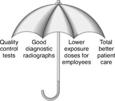
If the quality assurance program is the “umbrella” or management portion, then the quality control segment covers the integrity and function of the equipment and the measurement of image quality (Fig. 10-1).
The purpose of a quality assurance/quality control (QA/QC) program is threefold. First, it provides a way to minimize the dose of radiation not only to the patient but also to the persons who are assisting with the radiograph. Second, it allows production of quality radiographs that provide information for an accurate diagnosis. Third, its use leads to a decreased number of repeated films and thereby reduces overall cost per examination.
QUALITY ASSURANCE/QUALITY CONTROL IN VETERINARY RADIOGRAPHY
Questions have been raised regarding the validity of a quality assurance program and quality control tests in a veterinary practice. The basis for these questions has been that the patients being radiographed are not human, and therefore the question of repeated radiographs and unnecessary radiation becomes moot. However, the consideration should be for the persons assisting in positioning the animal or otherwise involved with the procedure during the radiographic exposure. The issue is not whether the patient is human but the protection of any involved personnel from unnecessary ionizing radiation.
A veterinary technician is an important part of any quality assurance program. It is the technician’s job to do most of the quality control tests, interpret the data, and keep the records. The remainder of this chapter addresses these tests, their interpretation, and the records that should be kept.
For these quality control tests, the data gathered are objective. We are not dealing with opinions or personal preferences of contrast and image quality. The technician measures, plots, and analyzes the data. This information is gathered at a point that is not yet visible to the eye on the radiograph.
Equipment
The actual equipment used to perform quality control testing depends on the size of the facility or practice. For a small facility, the equipment listed following is sufficient for an informative quality control testing protocol.
These items should be stored within easy access—and together—to eliminate confusion and delay when it is time to conduct the tests. Most of these tests are done only annually; if this is not the case, it is noted in the test procedure.
Tracking Charts
The purpose of tracking charts is to provide a means to record the data for ease in interpretation and tracking of results. There is no right or wrong way to keep this information except for the sensitometry/densitometry tests. The charts that the technician makes and relies on for tracking the equipment parameters are the mainstay of the quality assurance program. With charting, it is easy to inspect the data from the measurements and assess any changes. Changes that do occur can be brought to the attention of the veterinarian before they cause a problem that necessitates a second radiograph. When the charts indicate to the technician that the control limits have been reached or exceeded, action should be taken immediately.
Procedures
The procedures for using the test equipment are described in detail with each test. The following tests can be conducted frequently, as they are easy to do and provide the practice with a quick look at the physical nature of the radiographic equipment and the environment.
Equipment Needed
Graph paper or commercially prepared tracking charts
Notebook or folder for retention of tracking charts
Simple instructions for use and interpretation
QA/QC TESTS FOR THE X-RAY APPARATUS
SOURCE-IMAGE DISTANCE (SID) MARKS
Equipment Needed
Tape measure
Carpenter’s level
Objective
To ensure the accuracy of the SID
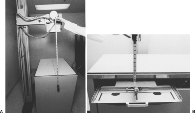
Procedure
1.
Using a steel measuring tape, measure from the focal spot mark on the tube housing to the tabletop. If there is no mark on the tube housing, simply divide the tube housing end cap into fourths. Using the bottom fourth as the focal spot, mark this on the end cap with a permanent marker and proceed with the measurement.
2.
Measure from the tabletop to the top of the cassette in the Bucky tray.
3.
Add these two numbers. They should equal the SID that is marked (
Fig. 10-2).
4.
Measure the marks on the tube stand for accuracy as well. Replace any “missing” marks with permanent marker, nail polish, or paint. If the collimator has a tape measure on it, check this for accuracy with the external tape measure. This information should be recorded for comparison and included in the quality control tests notebook or file.
QA/QC TESTS FOR THE X-RAY APPARATUS
PERPENDICULARITY
Equipment Needed
Carpenter’s level
Objective
To ensure that the x-ray beam is properly centered, we must be sure that the tube stand, collimator, and x-ray tube are perpendicular and properly aligned.
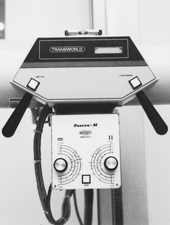
Procedure
1.
When the x-ray tube is positioned in the normal position, use the level to confirm that the tube is level and parallel with the table (
Fig. 10-3). Stand at the end of the table and look at the tube, collimator, and tube stand. Visually verify that they appear to be perpendicular.
2.
Stand alongside the table and verify the same information regarding perpendicularity of the collimator, x-ray tube, and tube stand.
3.
If the tube, the collimator, or the tube stand looks crooked or canted, adjust it or have it repaired before attempting any alignment tests or taking any radiographs. This information should be recorded along with whether the test was negative, what was canted, and how it was corrected. If the equipment was serviced, the repair report should be kept for future reference. The information should be recorded for comparison.
QA/QC TESTS FOR THE X-RAY APPARATUS
TUBE/TABLE/CRANE LOCKS
Objective
To check the function of the locks to eliminate any unnecessary motion from the x-ray tube, table, or crane.
Procedure
1.
Physically place locks on and off to see whether they lock securely and unlock properly.
2.
Check to make sure that the lock switch itself is not broken and that it functions properly. This should be recorded for future reference.
QA/QC TESTS FOR THE X-RAY APPARATUS
X-RAY FIELD LIGHT
Equipment Needed
Water and cloth
Objective
To ensure that the field light can be seen properly with the normal lights on in the radiographic room.
Procedure
1.
Turn off the power to the machine. Wash the plastic covering of the x-ray collimator with warm water and mild soap. The plastic covering over the tube output area should be clean and free of debris and dirt. If not, artifacts can show up on the radiograph. (Note: On some older equipment, the plastic covering may be part of the filtering of the x-ray beam. If this is the case, do not damage or remove it without having a serviceperson correct the filtration on the equipment.)
2.
Turn on the power to the machine. To check the brightness of the light, leave room lights on and turn on the collimator light. If there is no difficulty in seeing the edges of the field, there is no problem.
3.
If the dimensions of the light field are difficult to see, there is a problem. A serviceperson should be called to increase the light intensity, and a record should be made for future comparison and reference.
QA/QC TESTS FOR THE X-RAY APPARATUS
LIGHT FIELD SIZE
Equipment Needed
Steel tape measure
Objective
To ensure that the light field determined by the collimator dials is accurate.
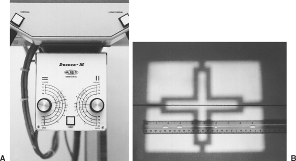
Procedure
1.
Using the tape measure, verify the SID to the tabletop.
2.
Set the collimator size indications at some field size. Remember to use the score for the SID you use routinely. An example of a field size to use is 8 × 10 inches (
Fig. 10-4).
3.
Turn on the collimator light.
4.
Using the tape measure, measure the light field on the tabletop. This measurement should be within 2% of the SID for light field accuracy. This should be recorded for future comparison and reference.
QA/QC TESTS FOR THE X-RAY APPARATUS
COLLIMATOR/CONES/DIAPHRAGMS
If the x-ray equipment does not have a lighted collimator but uses slide-in diaphragms to collimate to the cassette sizes, this test should be conducted.
Equipment Needed
One cassette to match each of the cone/diaphragm sizes or diameters
Objective
To ensure that the cones or diaphragms used are the correct size for the cassettes available for use within the practice.
Procedure
1.
Slide the different cones/diaphragms into or onto the x-ray tube, one at a time.
2.
Place the appropriate size cassette in the Bucky tray (be sure to recheck the SID).
3.
Make an exposure. Use a technique for this exposure that is approximately that for fetlock or carpus.
4.
Develop this film. The corners of the developed film will be clear (as if cut off) if the cone/diaphragm used matched the size of the cassette used in the Bucky tray. If there is no Bucky tray and all the radiographs are done tabletop, then do this test tabletop, making sure that the SID is accurate. Record this information in the QA/QC file for future reference.
QA/QC TESTS FOR THE X-RAY APPARATUS
LOCKS/CABLES/OVERHEAD CRANE MOVEMENT
Equipment Needed
None, except the x-ray equipment
Objective
To ensure adequate locking and movement so that the x-ray tube does not drift during the exposure.
Procedure
1.
Lock and unlock the locks. When each lock is in the locked position, the item that you are testing should not be able to move. For example, if you are testing the Bucky tray lock, then in the locked position, you should not be able to move it. If you are testing x-ray tube motion, then in the locked position, you should be unable to move the x-ray tube.
2.
To assess the overhead crane movement, the x-ray tube must be moved around its known limitations. The tube should move easily and without obstruction. Record this information for future reference.
QA/QC TESTS FOR THE X-RAY APPARATUS
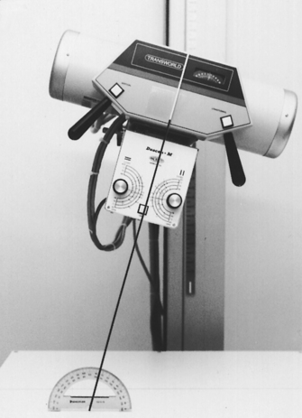
ANGULATION INDICATOR
Equipment Needed
Carpenter’s level
Protractor
Objective
To ensure that the angle indicator is correct when using any angulation on the x-ray tube for a radiographic exposure.
Procedure
1.
Place the carpenter’s level on the tabletop—it should be level.
2.
Place the carpenter’s level on the bottom of the collimator—this also should be level.
3.
Note that at both places the appropriate indicators should be zero.
4.
Rotate the x-ray tube to 15 degrees, and using the protractor, measure the degree of angulation. This should also be 15 degrees.
5.
Repeat this rotation of the x-ray tube to 30 and to 45 degrees, reading the angle indicator and measuring each degree change with the protractor (
Fig. 10-5). Record this information for future reference.
QA/QC TESTS FOR THE X-RAY APPARATUS
VIEW-BOX UNIFORMITY
Equipment Needed
Light meter
You can use a photographic light meter if it has a measurement scale. With certain types of photographic light meters, the denominator of the shutter-speed light intensity is in foot-candles.
Objective
To ensure uniform bulb intensity and color for even-light transmittance in radiographic evaluation.
Procedure
1.
Unplug the view box from the electrical outlet. Clean the view box inside and out. Use a soft cloth and warm water with mild soap. Do not use nail polish remover or other harsh abrasives because they will scratch the view-box surface.
2.
When cleaning inside, ensure that the bulbs are the same brand and the same color (e.g., daylight or soft white).
3.
To measure the intensity of the lights, turn on the view box 2 minutes before doing the test. This allows the bulbs to stabilize.
4.
Turn off all the room lights.
5.
Measure the intensity with the light meter at three different areas on the viewer.
6.
Calculate the average of the intensity on the viewer. An average or normal range is 400 to 580 foot-candles. Record this average information to monitor the life of the bulbs and their intensity as they age.
QA/QC TESTS FOR THE X-RAY APPARATUS
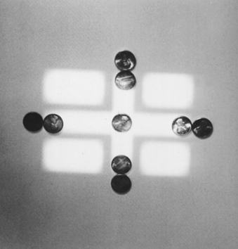
LIGHT FIELD/X-RAY FIELD ALIGNMENT
Equipment Needed
Nine pennies
10- × 12-inch cassette loaded with film
Objective
To ensure that the x-ray field is actually going where the light field indicates.
Procedure
1.
Center the x-ray tube over the table.
2.
Set the SID to 40 inches or your normal SID, and verify that the collimator is level.
3.
Put a cassette in the Bucky tray.
4.
Center to the tray under the table.
5.
Set the collimator field indicators at a field that is approximately 6 × 8 inches.
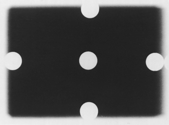
6.
Turn the collimator light on. Place one penny in the middle of each edge of the light field inside the light and one penny in the middle of each edge of the light field outside the light. The edges of the pennies should have the light field running between them, but the pennies should be touching (
Fig. 10-6).
7.
Make an exposure. The technique should be approximately the same as for a carpus or a stifle.
8.
Develop the film. When developed, the radiograph should show the pennies just as they were placed on the table, on either side of the light field. If it does not, the collimator needs adjustment (
Fig. 10-7). The width of a penny is 0.75 inch, and 2% of a 40-inch SID is 0.8 inch. Therefore if the x-ray field is off by the width of one penny, it is time to call service personnel.
To ensure that the center of the light and the x-ray field are aligned, draw diagonally from corner to corner on the film itself (all four corners). Make the same drawing from corner to corner on the exposed part. These two pairs of “Xs” also should not be apart by more than 2% of the SID. If they are, realignment by service personnel is necessary. Record this information in the QA/QC file for future reference.
QA/QC TESTS FOR THE X-RAY APPARATUS
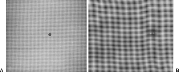
SCREEN-FILM CONTACT
Equipment Needed
Copper wire mesh contact tool with ⅛-inch spacing of the wires
Densitometer
Objective
To ensure that the adhesive on the back of the screens within the cassettes is still holding the screen tightly.
Procedure
1.
Each cassette to be tested should be allowed to sit for about 10 minutes before this test is performed. This allows any trapped air (from loading the film) to dissipate.
2.
Place the cassette on the tabletop.
3.
Place the cassette so that the long axis is perpendicular to the anode-cathode axis of the x-ray tube. This is to minimize the anode heel effect.
4.
Place the wire mesh over the cassette.
5.
Use an SID of at least 40 inches.
6.
Cone down to the size of the cassette.
7.
Make an exposure using approximately a carpus or a stifle technique for tabletop.
9.
When viewing the film, place it on a view box in a dimly lit room.
10.
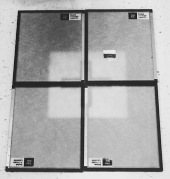
Stand approximately 6 to 8 feet back from viewer. You will be looking for areas of darkness or unsharpness on the film. Areas of poor contact appear as dark areas on the film (
Fig. 10-8). If this area is in the middle of the cassette or in an area where you are likely to have a patient’s area of interest, this screen should be adjusted. This may be as simple as regluing the edges of the screen to the felt. Any household white glue (e.g., Elmer’s) can be used, or you can use double-backed tape (e.g., carpet tape). The screens in the cassette may need to be replaced. This test must be done on all cassettes.
QA/QC TESTS FOR THE X-RAY APPARATUS
UNIFORMITY OF SCREEN SPEED
Equipment Needed
Control cassette for each speed within the practice (usually one that is the newest or most consistent for exposure)
Densitometer
One box of film, to be used with each screen size within the practice
Objective
To determine periodically whether screens have lost speed through wear and tear.
Procedure
Before starting, visually inspect each cassette for properly functioning locks, intact hinges, and screen-felt contact. The screens should be checked for scratches, worn spots, or chips and should be clean.
1.
Sort all the cassettes by screen type or speed group (high-speed, par, detail, rare-earth). Test each speed group separately.
2.
Select one cassette from a sorted speed group as the control cassette.
3.
Record the number of this cassette so that you can repeat this test when needed.
4.
Load the cassettes from the film box designated for this procedure. Cutting a 14- × 17-inch film into fourths and placing one fourth into one corner of each cassette helps limit the cost of this procedure. Just remember which corner of the cassette has the film in it.
5.
SID should be at least 50 inches if possible. You may have to put the cassettes on the floor to get this distance.
6.
Place the corners of the cassettes together.
7.
Center the x-ray tube over the area where the cassettes meet.
8.
Cone down to approximately 8- × 8-inch field size.
9.
Mark the cassette that is the control, and place this cassette into the upper-right-quadrant position of the four cassettes (
Fig. 10-9).
10.
Make an exposure, using approximately a carpus or a stifle technique. A technique that could be used for a medium-speed system is 10 mAs at 50 to 60 kVp. For a faster speed system, 5 mAs at the same range of kVp would be acceptable.
12.
Read the density of each film in the center on the densitometer.
13.
Record the density for each screen.
14.
Repeat this procedure until all the screens within the same speed group have been tested.
15.
Determine the average density of the films for each speed group. Divide the measured density of each film by the density of the control to determine each screen’s ratio.
16.
If there is more than one speed in the practice, this procedure must be repeated for the other speed groups, starting from the choice of a control cassette to the recording of the densities. The range of acceptable ratios between screens is between 0.85 and 1.15. Any screen that falls outside the ratio range should be removed from service. Record this information for future reference.
QA/QC TESTS FOR THE X-RAY APPARATUS
MACHINE PARAMETERS FOR CALIBRATION (kVp, mA, TIMER, AND FILTRATION)
Calibration should be conducted at least annually. The rationale for calibrating the x-ray equipment is to ensure that when 80 kVp is chosen, 80 kVp is delivered. Likewise, it is done to ensure that the mA stations and the timer are correct. Calibration involves a series of tests that a serviceperson must perform.
For example, a parameter that can change is kilovoltage. As an x-ray machine ages, kilovoltage can fluctuate. This problem also can be caused by incoming line voltage. Many veterinary clinics do not have a dedicated line for the radiographic equipment, and the voltage can change dramatically with an increase or a decrease in the incoming line voltage. This, of course, affects the penetration on the radiographs. Another possible source of kilovoltage fluctuation is bad internal workings—a computer chip, board, or drive that is not functioning correctly. These problems will be apparent in radiographs that are incorrectly penetrated and need to be repeated.
Darkroom Quality Control
Darkroom cleanliness is so important for good film processing that it is addressed separately. Just wiping up the counter is not enough, but it is a start. There must be no eating and no smoking in the darkroom. Crumbs in the cassettes can cause artifacts that could be interpreted as part of the diagnosis for the patient. Remember that the lit end of a cigarette is not a “safe” light and can fog your radiographs. This type of fog is called darkroom fog. Darkroom fog, no matter what the cause, is unacceptable. Fog can be caused by white-light leaks from around a door, cracked safelights, improper-wattage bulb in the safelight, improper safelight filter, safelight too close to the counter with a too-high wattage bulb, improper chemical temperature, or improper chemical balance.
QA/QC TESTS FOR THE X-RAY APPARATUS
FOG TEST
Equipment Needed
Lightly exposed radiograph
Watch or timer
Densitometer
Objective
To assess any fog in the darkroom that may be adding unwanted density to the radiograph during processing.
Procedure
1.
Expose a cassette with a film in it, using a small-extremity technique.
2.
Take the cassette into the darkroom.
3.
Remove the film from the cassette, place the film on the counter, and cover half of it with the cassette.
4.
All the safelights should be on, as in routine processing of a radiograph.
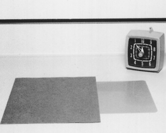
5.
Leave the film and cassette in this position for 2 minutes by the watch or timer (
Fig. 10-10).
6.
Process the film normally.
7.
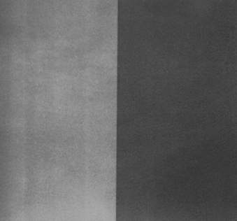
When the film has been processed, notice the difference.
8.
Measure each side of the radiograph with the densitometer. The difference should be no greater than 0.08 optical density (OD) for routine film-screen combinations and routine darkroom processing. If the difference is greater than 0.8 OD, the source of the radiographic fog must be located (
Fig. 10-11). This test should be done quarterly because it provides a good follow-up on fog. Record this information for future reference.
QA/QC TESTS FOR THE X-RAY APPARATUS
SENSITOMETRY AND DENSITOMETRY
Equipment Needed
Film, one box designated for sensitometry (this should be the same type/speed used every day but of the smallest size [i.e., 8 × 10 inches])
Sensitometer
Densitometer
Sensitometry graph paper
Thermometer
Objective
To ensure that the processing of the radiographs is optimized, thereby providing the best-quality radiograph. This is done by testing the processing procedure using a constant nonradiographic light source.
Procedure
1.
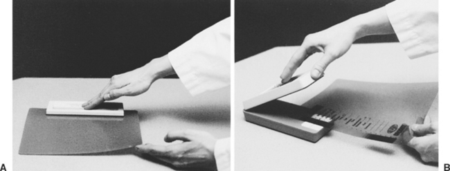
In the darkroom, before doing anything else in this procedure, take the temperature of the developer in the processor or hand tank.
2.
Using the sensitometer, expose one edge of a piece of radiographic film from the box of film dedicated for sensitometry (
Fig. 10-12).
3.
Process the film normally.
4.
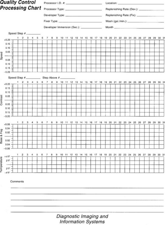
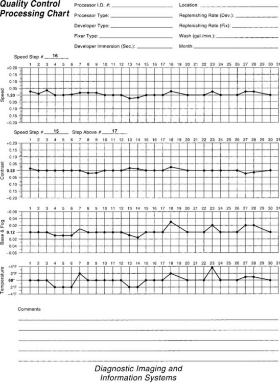
After the film has been processed, read the optical density of the steps with the densitometer and record the result on the graph paper (
Fig. 10-13) according to the following procedure.
5.
Measure the density in the center area of the film without any exposure.
6.
Plot this densitometer reading (number) in the base + fog area on the graph.
7.
The base + fog should not increase more than + 0.05 from the original or normal reading.
8.
Next, read the steps of the sensitometry exposure and record the numbers on either the film or a piece of scratch paper. These numbers determine which step should be used for the contrast strip and the speed strip.
9.
From these numbers, determine which step is within a density range of 1 to 1.3. This is known as the speed step.
10.
Plot the density reading for the speed step in the area on the graph. This step is used for the speed step for the entire box of sensitometry film. Variations should not be greater than ± 0.15 of the initial reading. If they are beyond this parameter, corrective action must be taken.
11.
Using the numbers for the steps off the scratch paper, determine the density of the steps above and below the speed step.
12.
Subtract these two densities for the reading for the contrast strip. These two steps will be used for the contrast strip for the entire box of sensitometry film.
13.
Plot this number on the graph portion for contrast. The variations should not be greater than ± 0.2. If they are beyond this parameter, corrective action must be taken (
Fig. 10-14).
14.
These densities from the same steps on the sensitometry strip should be read and plotted daily on the graph paper.
It is imperative that this sensitometry and densitometry test be done each day any radiographs are processed. The purpose is to determine the processing environment before films are taken and thereby reduce the need for retaking films. (Note: All sensitometers and densitometers come with detailed instructions on how to do the procedures and the corrective actions to be taken when test results are outside the designated parameters.)
KEY POINTS
1.
The purpose of a QA/QC program is to provide a way to minimize the dose of radiation to the patient and personnel, to allow production of quality radiographs to help with an accurate diagnosis, and to decrease the number of repeated films.
2.
QA/QC tests are intended to be interpreted objectively. Opinions and personal preferences are inappropriate responses.
3.
The majority of QA/QC tests must be performed annually; however, it is important to check the required frequency of each test because some have other than annual schedules.
REVIEW QUESTIONS
1.
The source-image distance QA/QC test requires measuring the distance from the bottom one fourth of the end cap of the tube housing to:
a.
the top of the cassette in the Bucky tray.
b.
the bottom of the collimator.
c.
the top of the cassette on the tabletop.
2.
What angles should be measured when performing the angulation indicator QA/QC test?
a.
10, 20, and 30 degrees
b.
10, 25, and 40 degrees
c.
15, 20, and 25 degrees
d.
15, 30, and 45 degrees
3.
When performing the light field/x-ray field alignment QA/QC test with a 40-inch SID, the collimator needs adjustment if the x-ray field differs from the light field by at least:
4.
When performing the screen-film contact QA/QC test, poor contact between the screen and felt of the cassette is seen as:
a.
whiter/lighter areas on the radiograph.
b.
darker areas on the radiograph.
c.
a completely black film.
d.
a difference of at least 2% between the light field and the x-ray field.
5.
When performing the fog test for QA/QC, the optical density between the two sides of the film should be less than:
6.
The sensitivity and densitometry QA/QC test should ideally be performed:
d.
when the technician suspects that the darkroom environment is not optimal.
7.
When performing the uniformity of screen speed QA/QC test, the range of acceptable ratios of the density of each film to the control film within one speed group is:
8.
The purpose of the quality assurance program is:
a.
equipment calibration.
b.
preventive maintenance.
c.
education of personnel.
9.
Darkroom fog:
a.
is tolerable as long as all of the other radiographic parameters are in compliance.
b.
can be caused by an improper wattage bulb in the safelight.
d.
Both b and c are correct.
10.
The average, acceptable range of intensity for the view-box uniformity QA/QC test is:
b.
40 to 50 foot-candles.
c.
400 to 500 foot-candles.
d.
500 to 1000 foot-candles.