chapter 22 Digital Radiography
Upon completion of this chapter the reader should be able to do the following:
ADC: Analog to digital converter. An electronic device that converts an analog voltage signal to a digital signal.
ALARA: As low as reasonably achievable. This acronym refers to a basic principle of radiation safety—to use the lowest amount of ionizing radiation as possible.
Analog: A voltage waveform that is continuous; at any point in time there is a voltage value.
Bit: A binary digit, either 0 or 1.
Bmp: Bit map. A representation of a graphic image stored in computer memory as rows and columns of dots; each dot is stored in one or more bits of information. Dot density, or resolution, is expressed as dots per inch (dpi). Images displayed on a monitor are converted from bit maps to pixels.
CCD: Charged coupled device. A small flat panel device that is capable of creating images from visible light, used for digital radiography and digital photography.
CD-ROM: Compact disk, read-only memory. A CD-ROM (or CD) is a 5-inch diameter optical storage device with a capacity of approximately 700 megabytes (MB).
Compression: A mathematical reduction in size of digital data so that they are easier (faster) to transmit. Loss-less compression allows perfect decompression of compressed data without loss of information. With lossy compression, a portion of original digital data is lost and cannot be restored. The advantage of lossy compression is that higher compression levels can be attained.
Contrast resolution: The ability to distinguish between two structures of differing x-ray attenuation. The high-contrast resolution of digital radiography is vastly superior to conventional screen-film radiography.
CR: Computed radiography. A type of digital radiography that uses a photostimulable phosphor plate for image acquisition.
DICOM: Digital Imaging and Communications in Medicine. The global standard in the human medical industry for transmission of medical images and related information. A joint committee of the American College of Radiology and the National Electrical Manufacturers’ Association (ACR-NEMA) is responsible for the continuous development of DICOM standards. DICOM is intended to realize the interoperability of multiple medical imaging devices manufactured by different vendors including the display and transmission of images and information.
Digital: To use digits (rather than numbers); data stored, displayed, or represented in numerical digits (binary). Images are converted into electronic bits.
DDR: Direct digital radiography. A digital radiography system in which there is direct conversion of x-ray energy into an electronic (digital) signal. Although DDR offers the best in digital radiography resolution, the technology is currently expensive and not yet commonly used.
DR: Digital radiography. Term used to denote any type of digital radiography including computed radiography, CCD technology, flat panel detectors, and direct radiography units.
DVD: Digital video (versatile) disk. A 5-inch diameter optical disk with approximately 5 gigabyte (GB) storage capacity.
Ethernet: A low-level networking standard used in local area networks. It defines wiring specifics and types of electrical signals transmitted.
Firewall: An electronic “security wall” that connects two or more computer networks yet secures one network from the other.
FTP: File transfer protocol. A high-level protocol designed for reliable transfer of digital files from computer to computer via the Internet. Transmission requires permission of both the sender and the recipient. A variant of FTP, anonymous FTP, allows information to be accessed by logging in a user name of anonymous. A Web database of anonymous FTP sites is termed “Archie.”
HIS: Hospital information system. A computer-based information system necessary to manage a health care facility. Patient information, admission and discharge, billing, scheduling, medical procedures, and pharmacy are items that may be included in an HIS. Ideally, the HIS is integrated into the radiology information system.
HL-7: Health level 7. A nonprofit organization founded in 1987 that develops standards for transmission of electronic clinical, financial, and administrative data among health care computer systems.
HTTP: Hypertext transfer protocol. A high-level Internet protocol that defines the World Wide Web (www). This protocol allows Web browsers to speak to Web servers. Hypertext markup language (HTML) is the language used to transmit information.
Internet: Computers world wide connected by common high-level communication protocols using TCP/IP lower layer communication language.
IP: Internet protocol. A low-level protocol used to assign computer addresses. The addresses consist of 4 numbers between 0 and 255, each separated by a period (e.g., 199.193.45.7)
Jpeg (jpg): Joint Photographic Experts Group. A lossy compression technique and popular image format used to minimize file size and download time. It reduces file size to as low as 5% of the original size, with a loss of image resolution.
Matrix: A grid arrangement of pixels, expressed as numbers representing the amount of horizontal and vertical pixels used (e.g., 256 × 256).
PACS: Picture archiving and communication system. A broad term involving computers and components used to capture, transfer, store, and display medical digital information.
PSP: Photostimulable phosphor.
RAID: Redundant array of inexpensive disks. Multiple inexpensive disk archives are configured such that storage, access, and redundancy of information can be increased more reliably than by use of a single, larger-capacity disk.
RIS: Radiology information system. A computer system that handles all of the information necessary to operate a radiology department. RIS manages patient information, scheduling of imaging procedures, radiology reporting, and a database allowing case search capabilities. HIS, RIS, and PACS systems must communicate effectively.
Scintillation devices: Materials that emit visible or ultraviolet light when exposed to x-rays.
SCP: Service class provider. The DICOM term for a server program.
SCU: Service class user. The DICOM term for a client program.
Server: A computer system that provides information upon request from a client (user).
SMTP: Simple mail transport protocol.
Spatial resolution: The ability to distinguish between two small, separate structures. Loss of spatial resolution renders two closely spaced small objects to appear as one structure. Usually measured as line pairs per millimeter. The best screen-film systems still have better spatial resolution than digital systems, but this is compensated for by the increased contrast resolution that digital radiography offers.
TCP: Transmission control protocol. A protocol for breaking information into smaller packets for data transmission.
TIFF: Tagged image file format. A popular public domain raster file format for image storage. Digital radiographic images stored in TIFF format are not compressed and therefore are large files (megabytes).
WWW: World Wide Web. Internet computers that exchange information via the HTTP protocol.
INTRODUCTION
Computers have become an integral part of our daily lives. More than half of the households in the United States have computers, and 60% of adults and an amazing 84% of young people (3 to 17 years) use a computer at work, school, or home. Not surprisingly, radiology has entered the computer age. What is surprising is that as the oldest imaging modality, radiography has been the last to make the conversion to the digital age. This speaks highly of how well conventional film-based radiography has served the medical profession since Conrad Roentgen’s discovery of x-rays November 8, 1895.
HISTORY OF DIGITAL RADIOGRAPHY
Magnetic resonance imaging (MRI) and computed tomography (CT) began as digital imaging modalities with their inception in the 1970s, and ultrasound (US) and nuclear medicine (NM) have fully evolved into digital technologies. However, the evolution of digital radiography (DR) has been much slower, for two principle reasons. First and foremost, conventional screen film radiography has been used for decades and has served the medical profession well; there has not been a pressing need to convert to digital radiography. Secondly, the large field-of-view (e.g., 14 × 17 in radiographic image) and high spatial resolution of radiography require large amounts of digital data (4 to 32MB) and demand high-quality monitors for viewing when compared with MRI, CT, and US.
Although conventional radiography has been a mainstay in diagnostic imaging, we are now wholly entrenched in an era of computers and digital data. Over the past 20 years digital radiographic image receptors have steadily replaced traditional screen-film cassettes as human medicine radiology departments transition to a filmless environment. In the early 1980s Fujifilm Medical Systems introduced the first digital radiography technology, known as computed radiography (CR). Traditionally, high cost has limited CR to human medical facilities and a few select veterinary colleges and private specialty veterinary practices. Maturation of digital technology, with lower costs and available veterinary-specific digital imaging equipment, has now enabled veterinary medicine to realize the benefits of digital radiography. Veterinary digital radiography is now growing at a frenzied pace.
DIGITAL RADIOGRAPHY: AN OVERVIEW
The concept of digital radiography is quite simple. The primary difference between conventional film-based radiology and digital radiology is that radiographic images are electronically captured, recorded, and viewed at a computer terminal, replacing radiographic film and the view box. The conventional screen-film cassette is replaced by a reusable image receptor (detector). The image receptor receives x-rays just as conventional intensifying screens do. Instead of exposing radiographic film, however, intensifying screens or other scintillation devices expose a “digital plate” that transforms emitted light to an electrical latent image. The different ways in which this is accomplished are discussed in detail in the following sections. The x-ray tube, generator, and peripheral x-ray machine hardware are essentially the same for conventional or digital radiography. Indeed, many of the available digital radiography systems use preexisting x-ray equipment (Fig. 22-1).
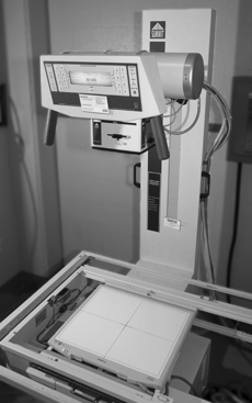
Figure 22-1 Conventional x-ray machine with a flat panel detector digital radiography system. The tabletop of the x-ray machine has been removed to show the position of the detector panel.
After the digital radiographic image is made, it is transferred to a dedicated digital radiography computer for “image processing” (Fig. 22-2). Here, the images can be adjusted as needed by the veterinary technologist. In small practices this may be the only computer available to view, but in most instances the processed image is finalized and then sent to another dedicated computer workstation for diagnostic interpretation by the veterinarian (Fig. 22-3). In large hospitals where multiple diagnostic workstations are necessary, the images will be sent to a main centralized computer (called a server) for storage and distribution to other workstation computers or sent off site via the World Wide Web for review.
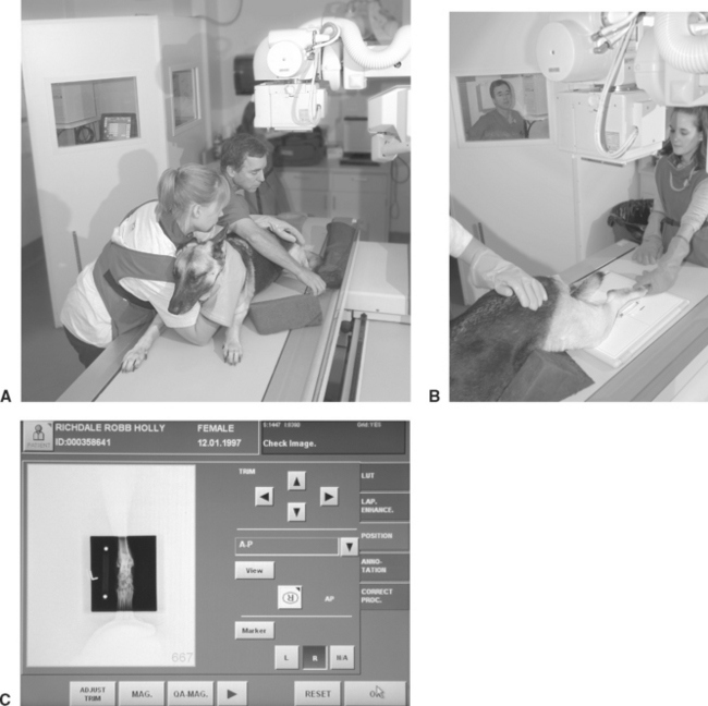
Figure 22-2 Making the digital radiograph. A, This German shepherd is prepared for a caudocranial view of the tarsus. The local digital work station and radiology controls are in the background, behind a leaded glass and wall. B, The flat panel detector panel is positioned on the tabletop for caudocranial radiography of the left tarsus. A 10-cm bar marker has been placed lateral to the limb to allow for computer correction of magnification. In this application the detector panel is mobile and can be used for a multitude of positional studies including horizontal beam radiography. The panel can also be placed under the table for conventional radiography, with or without a grid. The radiology technologist is seen in the background in the control area. C, The local digital work station where the radiographic image of the tarsus appears following exposure. On this “Position” screen, the technologist can alter the orientation of the image, magnify the image, and make masking adjustments (black-out the white collimation). Note the tabs to the left of the screen that offer further choices on image manipulation.
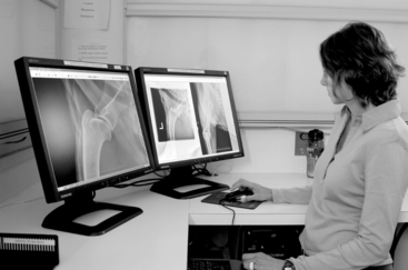
Figure 22-3 Diagnostic workstation. This workstation uses a dual-monitor viewing system. The image of the humerus on the left monitor has been magnified for close scrutiny; two images on the right monitor are unmagnified. The workstation software applications allow the veterinarian to perform a multitude of image manipulations to optimize the image for diagnosis.
The term picture archiving and communication system (PACS) is the broad term for computers and components used to capture, transfer, store, and display medical digital information. Digital images can also be printed on high-quality transparent film (laser printers) to be viewed at a conventional illuminated view box, though most practices that make the conversion to digital radiography opt to go “filmless,” one of the major advantages of digital imaging.
LIMITATIONS OF CONVENTIONAL SCREEN-FILM RADIOGRAPHY
Although conventional screen-film radiography has served the medical community well for many years, its limitations make digital radiography an attractive alternative. First, screen-film radiography requires fairly narrow exposure factors to produce a diagnostic quality radiograph. Because x-ray film has a limited linear response (recall the logarithmic toe, linear region, and shoulder of a radiographic film Hunter and Driffield curve), relatively small underexposure or overexposure may yield an unacceptable image. This is why a radiographic technique chart is required and radiographic technique adjustments are necessary for various anatomic areas (thorax, abdomen, skeletal); body part thicknesses (incremental changes in kilovoltage potential (kVp) per centimeter of body part thickness); and different screen-film speeds. In many instances the inherent latitude limitation of conventional screen film radiology means that some areas of the radiograph will be overexposed while other areas will be underexposed. Depending on technical factors chosen, the radiograph can be made with relatively high contrast (e.g., a low kVp bone technique) or wide latitude (more shades of gray, as desired for thoracic radiography), but not both. A compromise is always possible.
Another disadvantage with conventional screen-film radiography is that the radiographic image cannot be adjusted once made. The radiographic film is exposed and then processed and viewed. Any errors in the exposure cannot be remedied; the radiograph must be retaken. This leads to increase in radiation exposure to the technician and patient, increases the cost of the examination, and requires additional technician and veterinarian time. Because the digital image can be manipulated after it is made, overexposure and underexposure problems are essentially a thing of the past with digital radiography.
Traditional radiography requires handling of film for viewing, archiving (storage), and distribution to referring veterinary practices. Reviewing a radiographic examination from a remote location requires that the study either be copied and sent via courier or digitally scanned before electronic transmission. Film storage requires an area large enough to access and sort films, often a separate area from the patient’s medical records.
ADVANTAGES OF DIGITAL RADIOGRAPHY
The Image
Unlike traditional screen-film radiography, kVp has little or no effect on the contrast or latitude of the digital image (this can be endlessly adjusted with software at the digital radiography computer terminal and diagnostic workstation). This flexibility is possible because of the linear relationship of the image receptors used for digital radiography. Simplistically, the number of electrons “trapped” by the digital image receptor during an x-ray exposure is linearly related to the intensity of the x-ray beam. Digital images have more latitude (more shades of gray) than film images and can display high-contrast body parts while simultaneously displaying soft tissues. This high gray-scale (high latitude) resolution is desirable because it allows observation of minor differences in radiation attenuation that may not be visible with film. When compared with conventional screen-film technique charts, digital technique charts do not vary greatly for the body part radiographed or patient thickness.
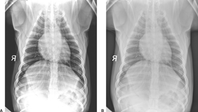
The higher-contrast resolution (or exposure latitude) of digital radiography has several tremendous advantages over conventional screen-film radiography. The need for retakes resulting from overexposure and underexposure is reduced, and for the most part eliminated. Images that are too light or dark that would be discarded on radiographic film can be adjusted with the digital image management software (Fig. 22-4). Marginal radiographic images, which may have previously been deemed acceptable, are a thing of the past.
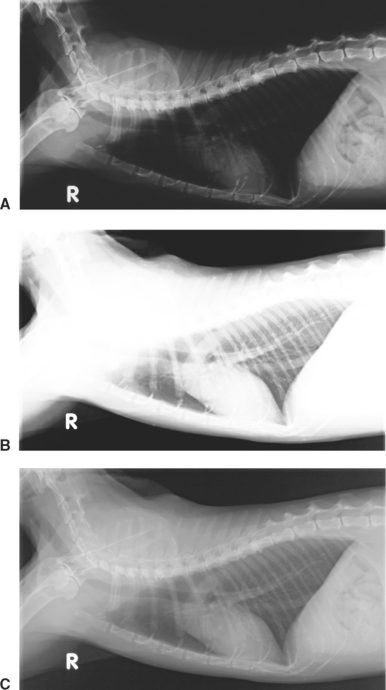
Figure 22-4 Lateral thoracic radiographic image of a cat illustrates how overexposure (A) and underexposure (B) can be image processed to produce a perfectly exposed image (C). With conventional film-screen radiography, the improperly exposed studies would require retaking the radiographs.
Computer manipulation of the digital image is a phenomenal advantage that digital radiography has over conventional screen-film radiography. Images can be altered for contrast or latitude (Fig. 22-5) and can be zoomed (magnified) (see Fig. 22-3) to scrutinize the image as if using a magnifying glass to view a radiographic film. Digital viewing software packages offer a variety of ways to view digital images including subtraction tools that make it possible to view bone-only or soft-tissue-only images from a single exposure. Digital radiography makes it possible to see both soft tissue and bony detail in a single image. Because of the high exposure latitude, an unprocessed digital image usually does not look the same as a film/screen radiograph. Although digital images can be manipulated to mimic the appearance of conventional radiographs (Fig. 22-6), usually the image is adjusted to take advantage of simultaneous high contrast and high latitude. Curiously, the appearance of digital images is resisted by some veterinarians who are accustomed to viewing high-contrast radiographs. Getting accustomed to viewing digital images is one small initial disadvantage of digital radiography, but quickly overcome.
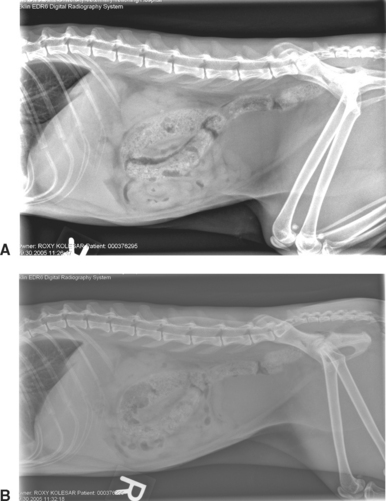
Figure 22-5 Feline digital abdominal image. A, High contrast image. Note the high contrast between bone, soft tissue, and fat. B, High-latitude image.
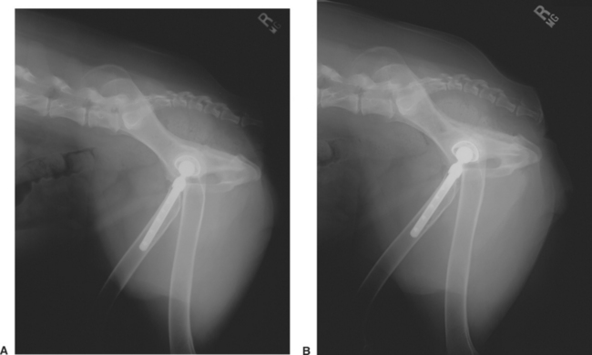
Figure 22-6 A, Conventional screen-film lateral pelvic radiograph of a dog with a total hip prosthesis. B, Digital radiographic image of the same patient. Note that high-quality conventional screen-film radiography can be similar to digital radiographic images.
The spatial resolution of digital images is at best the same, but usually slightly lower than a high-quality radiographic film image. This is not a disadvantage in most instances because there is a limit to how much spatial resolution the human eye can discriminate. As digital technology advances, differences in spatial resolution between conventional and digital radiography have become almost negligible. Human medical studies have shown that digital images are equal to or better than traditional film for evaluating most body parts. This is because there is a point at which spatial resolution yields way to contrast resolution (the ability to separate two structures of different contrast, or x-ray attenuation), the hallmark of what makes digital radiography so diagnostic. Image quality and the ability to detect abnormalities are actually more dependent on postdigital image acquisition processing than on spatial resolution. Digital radiography has been clinically validated for 20 years in various human medical settings including mammography, indicating that its minimally lower spatial resolution is not a clinical limitation.
Digital radiography software not only allows an image to be manipulated for optimum viewing, but also measured, drawn on, and annotated. Heart dimensions (e.g., the vertebral heart score), pulmonary nodule size, or hip or tibial plateau angles can be measured and stored. These measurements and comments can be printed directly onto the image, with the original image retained as a separate, unaltered digital file. Highlighting suspect areas and noting comments on the image can make future readings easier. Additionally, templates used for total hip replacement and tibial plateau leveling osteotomy procedures (TPLO) have now become incorporated into some vendor software, allowing surgical planning directly from the diagnostic workstation.
Time Savings
Digital radiography will decrease the time it takes to make radiographic images. This is especially true of charged coupled devices (CCDs) and flat panel receptor digital imaging systems because images are literally available for viewing several seconds following the radiographic exposure. CR has an inherent disadvantage in that each CR cassette must be processed in a manner similar to a conventional radiographic film processor. Of course, CR is definitely faster when compared with manual film processing. Still, all of the digital modalities will save time due to better-quality images and a reduced number of retake radiographs caused by technical issues. Radiology-related case management should be more efficient, as the veterinarian can obtain the image more readily, render a diagnosis or list of differential diagnoses, and communicate with the client sooner. This is especially true for clinics with manual processing or mobile practices. Practices that have inefficient workflow patterns will not receive maximum benefit of the time savings afforded by digital radiography.
Repeating radiographs (the dreaded “retake”) is common in veterinary medicine because of improper exposure techniques, patient motion, and positioning problems. Repeat radiographs are significantly reduced with digital radiography. Specifically, exposure-related retakes should be essentially eliminated. Secondly, patient motion artifacts can be reduced by reducing radiographic exposure time (selecting a higher kVp and a corresponding lower mAs technique). Recall that kVp is no longer a factor in radiographic image contrast and latitude, so this can be done without altering image contrast. It should be obvious that repeat radiographs require additional veterinarian and technician time and are costly in terms of wasted film and film development chemicals. Patient resedation and additional radiation and film development chemicals exposure to personnel are yet further concerns of retaking radiographs. Repeat trips to the clinic for the client and additional farm visits or house calls for the veterinarian are added examples of the negative impact of retake radiographs.
Image Storage and Transport
Digital images are stored on the local computer dedicated to the digital system. Images are typically transferred to a second computer (or “server”) for permanent storage and distribution (within large hospitals or distribution outside of the hospital). Image files can be stored or transferred in other formats (e.g., jpg, bmp, tiff) depending on the image management software. Like other computer files, these should be backed up to avoid loss or corruption of patient data. Backup strategies include copies to CD, DVD, additional hard drives, or outside archival sources.
One feature of digital image storage is that quick access and viewing is simply a computer search. No more hunting for lost radiographs! With today’s demand for fast information, having access to a digital file offers veterinarians a distinct advantage over retrieving and viewing a conventional radiographic film.
Digital storage allows easy transferability of images via electronic mail (e-mail). Veterinarians commonly send cases via the World Wide Web to consulting or referring veterinarians. In emergency situations, nearly instantaneous consultation could be lifesaving for the patient. Large images must be sent off site via file transfer protocol (FTP) or custom teleradiology systems or converted to compressed formats (e.g., jpg) for effective transmission. Network PACS that allow access to the database are found in larger practices or universities and can solve some problems (e.g., veterinarians can access the larger system from a remote location and view the radiographs without downloading them onto their own computer).
A CD of the images can be made for the client or for a veterinary colleague. Laser printers are available to print digital images on transparent film, similar to a conventional radiograph that is viewed on a view box. Clients may request and be happy with a paper print copy for their records. Equine practices may wish to provide radiographic or paper copies for clients and their farriers when corrective shoeing is indicated.
Cost Savings and Increasing Profits
Much has been written and spoken regarding the cost benefits of digital radiography. By most accounts, digital radiography makes fiscal sense. Although the overall cost of purchasing a digital radiography system is higher than that of a film developer (processor), there are a number of cost savings associated with digital radiography. Fewer retakes result in reduced use of the x-ray machine, there are no film processor expenses (chemicals and maintenance), film purchasing is no longer required, and radiography is less labor intensive. For high-volume practices, the monthly cost of film, processor maintenance, and chemicals may be higher than the monthly lease of a new digital radiography system.
Another consideration is that in most practices, digital radiography improves the quality of the imaging studies. This in turn leads to better diagnostic information and potentially increased profitability. Increases in efficiency and diagnostic capability will probably lead to an increase in the number of radiographic studies performed. Some clients may actually demand it, especially equine clientele. Digital radiography vendors are well versed in showing how your practice can make digital radiography not only cost effective, but profitable.
Follow-up Radiography
Sequential or follow-up radiographs are a component of good case management, to assess response to therapy, monitor progression of disease, etc. Comparison of follow-up images is easier with digital radiography than with traditional radiography, as the images can be manipulated to have the same degree of contrast and latitude. Although differences associated with phase of respiration or poor positioning may still occur, subtle differences that may be masked or overinterpreted due to exposure differences should be minimized. Also, prior images can be quickly accessed from computer archives for comparison (remember, no more lost or misplaced radiographs to search for). Ambulatory veterinarians can access prior images on site rather than returning to the hospital to make comparisons.
DISADVANTAGES OF DIGITAL RADIOGRAPHY
Training and Learning Curve
Disadvantages of using digital radiography are minimal when compared with the advantages already outlined. These include changing and getting accustomed to a new imaging system, the need for personnel training, and cost. Manipulation of digital images takes time and practice and is somewhat dependent on the user’s computer skills.
Digital manipulation cannot make all images useful. Gross errors in exposure factors or patient motion cannot be overcome with image enhancement. Veterinarians must also be careful not to overprocess an image and create artifacts (e.g., apparent lesions) through software manipulation. Comparing the unprocessed image with the manipulated one is a way of detecting processing artifacts.
Digital radiography will not compensate for poor radiographic techniques or poor staff training. Improper labeling or misidentification of patients will undermine image storage and retrieval functions. Investment in a new digital radiography system should establish a renewed commitment to diagnostic imaging.
Equipment Costs
Digital radiography systems are costly, although their prices are falling and they are affordable and economical for most practices. Direct costs include the computer hardware, software, and optional higher-quality paper for printing (images are to be viewed on the monitor for diagnosis and reading fine detail). The initial cost of the digital radiography system must be weighed against the benefits of becoming filmless, using less film and chemicals, and the important benefit of increased efficiency. The cost savings of a digital radiography system grows over time as the number of retakes is reduced.
The cost of consumables in conventional screen-film radiography includes film, film jackets, fixer, developer, and disposal of toxic chemicals. Digital technology eliminates those costs. Recall that digital images must be backed up just like other computer files. If veterinarians want printed copies of each image, hard-copy storage space will not be reduced.
HIS, RIS, and PACS
Nearly all veterinary practices now have some form of computerized hospital patient identification and medical record keeping or hospital information system (HIS). A HIS is a computer program that allows patient information to be entered into the hospital computer system upon admission. It can be used for electronic medical record keeping. Ideally, the HIS communicates with the digital imaging system directly or via a radiology information system (RIS). Patient information is thus entered into the hospital computer system only once, interfaced with the RIS for immediate access to patient identification and imaging procedure.
The type of imaging studies required, the scheduling and status of the radiography examination, and even the radiology report are functions of an RIS interfaced with HIS, with information stored, accessed, and distributed via the PACS. Digital images can also be placed into electronic patient records, one step closer to an integrated and totally digital (paperless) medical record system. The PACS server can accommodate all forms of digital imaging technology such as ultrasound, computed tomography, nuclear medicine, and magnetic resonance imaging. Other digital imaging examinations such as endoscopy can also be stored and viewed via PACS.
As mentioned previously, the term PACS encompasses computers and related components used to capture, transfer, store, and display medical digital information. In addition to the multitude of PACS created for human medical use, veterinary-specific PACS have been developed by a number of vendors. PACS allow communication between computers. Some users of digital radiography do not use PACS but instead simply use the image software provided by the manufacturer to manipulate and view the data. However, this severely limits the ability to distribute digital images for consultation. For large practices, some form of PACS is necessary to realize all of the advantages of digital radiography.
Digital Imaging and Communications in Medicine
The American College of Radiology and the National Electrical Manufacturer’s Association formed a joint committee to develop a global standard for Digital Imaging and Communications in Medicine (DICOM). DICOM was intended to realize the interoperability between multiple devices manufactured by different vendors (e.g., transmission of images or information, displaying of an image). DICOM’s scope is diagnostic imaging. DICOM images are embedded, extensive, detailed, and specific information. DICOM embedded information cannot be altered. Each piece of DICOM equipment is uniquely identified such that a DICOM image can be precisely identified as to its origin; each DICOM image is unique.
The DICOM standard is now embraced by the veterinary imaging community, ensuring the highest possible standard of quality. DICOM compliance assures that digital images can be transferred and read safely by any DICOM workstation software.
IMAGE MANAGEMENT SOFTWARE AND IMAGE PROCESSING
Before digital image acquisition, patient information is entered into the digital radiography computer. If an HIS is interfaced to the digital radiography computer (this may be direct or more commonly via a RIS), this information is automatically entered into the digital radiography computer, a significant savings. In the best systems, there are preset selections available for species, body part of interest, and radiographic view to further identify the study type. Following acquisition, the digital image is viewed on the digital radiography computer for processing (see Fig. 22-2). Here, the image can be adjusted if necessary in a variety of ways using manufacturer-specific software. Image processing tools include brightness, contrast, magnification, inverting black and white, edge enhancement, a number of image processing curves (algorithms), and image cropping and masking. The digital radiography image processing software is manufacturer specific and is an area of rapid development in veterinary medicine. Use of equipment designed for human use requires adoption of software for veterinary use for optimum realization of digital imaging. Understanding and learning how to use this software is one of the biggest challenges for the veterinary technologist when converting to digital radiography.
In small practices the digital imaging computer may be the only computer available, especially if digital images are printed on transparent film for viewing. In most instances, however, the processed, finalized images are sent to a dedicated computer workstation for diagnostic interpretation by the veterinarian (see Fig. 22-3).
ANALOG-TO-DIGITAL RADIOGRAPHIC SIGNAL CONVERSION
A conventional radiograph is produced by a series of analog signals, from x-ray formation and interaction with the patient, to capture of x-rays by the intensifying screen, which in turn emit light that exposes the radiographic film. The final radiographic image results by development of silver halide contained within the emulsion of the x-ray film. As previously mentioned, the origin of a digital radiographic image is identical to a conventional radiographic image. The difference is conversion of the analog signal (light emitted from scintillation screens) to an electronic digital signal by use of a digital radiographic device, explained in detail shortly.
An analog signal is a waveform—a continuous electrical signal. Its electrical value is represented as a voltage value. A digital signal is produced from an analog signal by way of an analog-to-digital converter (ADC). The ADC samples the analog waveform and transforms it into a “stepped” representative signal. The more times the analog signal is digitally sampled, the closer the digital waveform is to the original analog waveform. The frequency of digital sampling is termed sampling rate. Sampling rates in the 10s to 100s of thousands per second are necessary to accurately digitally replicate an analog waveform. An analog waveform and its digital conversion are depicted in Figure 22-7.
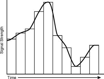
Figure 22-7 Analog-to-digital (ADC) waveform conversion. The analog waveform is the curved continuous black line. Conversion of this analog waveform to a digital waveform is accomplished by a series of “steps.” Note that the digital waveform only approximates the original analog signal. The number of digital “steps” per unit time (seconds) is termed sampling rate. The more digital samples per unit time, the higher the sampling rate and the closer the digital sample to the original. In this example the sampling rate is low. An ADC is used to make the conversion from analog to digital waveforms.
DIGITAL COMPUTERS
For many people familiar with personal computers, terminology used for digital imaging computers is already part of their daily vocabulary. For others, a comprehensive review of digital computers is beyond the scope of this chapter. Nonetheless, is important for the veterinary radiology technologist to be at least familiar with the concepts and terminology of computers as used in digital imaging.
The digital waveform is represented numerically for computer analysis by binary numbers. Unlike the base 10 (decimal) numerical language that we are all familiar with (ten digits, 0 through 9), the binary system uses only two digits (0 and 1) to represent numbers. The smallest binary number is termed a bit and has four numerical possibilities (0; 0.1; 1,0; 1,1, which correspond to the numbers 0, 1, 2, and 3, respectively). Electronically, this can be thought of in terms of an ON/OFF switch, where 0 is off and 1 is on. Large numbers are represented by a series of 0s and 1s. This is convenient because any given numerical value can be represented electronically by a series of ON/OFF switches.
Each digital sample is assigned a binary value on the basis of the voltage signal strength of the original analog waveform. Between 8 and 12 bits are used in digital imaging to represent digital voltage values. Depending on equipment specifications, each pixel (defined shortly) will be assigned a binary number between 0 and 255 (8 bits of information, or relatively poor resolution) to as high as 0 to 4095 (12 bits of information, high resolution). Digital radiography requires 10 or preferably 12 bits of numerical value per pixel for diagnostic resolution. The more bits available, the larger the range of possible numbers stored per pixel. This translates into increased contrast resolution, the various shades of gray between black and white. These numerical values are then displayed as a particular corresponding shade of gray on the video monitor. The more shades of gray, the better, and this is known as “image depth.” As discussed later, many display options are available to maximize the diagnostic quality of the digital image. As an aside, lack of bit or image depth is one reason that a digital photograph of a conventional radiograph made from an illuminated view box is not satisfactory for all but the most obvious lesion. A digital photographic image of a radiograph is NOT of the same diagnostic quality as a true digital radiograph.
Computer memory and storage consist of bits (for binary digits), each bit representing one binary digit. Eight (8) bits are grouped into a larger unit, termed byte. One byte (or 8 bits) has 256 number configurations of 0 and 1s (numerical values of 0 to 255), whereas 2 bytes (16 bits) has 65,536 possible configurations (numbers of 0 to 65,535). Computer capacity is described in kilobytes (210 bytes, or 1000 bytes), megabytes (220 bytes, a million bytes), gigabytes (230 bytes, a billion bytes), and terabytes (240 bytes, a trillion bytes). Terabyte storage capability is required for large hospitals using digital imaging modalities. Bits are also grouped into larger units, called words. This terminology is important when assessing computer usable memory, storage capacity, and digital radiography specifications.
As you can see, the computer is at the heart of digital image processing. Advances in imaging have gone hand-in-hand with increases in computer speed and storage capabilities. Computers allow digital information to be processed and viewed in the most diagnostic manner. It is emphasized that computer processing of digital images does not add any new information to the digital image; it only changes the way in which we view the image. Still, manipulation of the image allows a phenomenal variety and number of viewing options that may allow a diagnosis to be made that would otherwise go undetected.
PIXELS AND IMAGE MATRIX
In digital radiography the x-ray beam is converted into an electronic form that is digitized and numerically encoded into millions of tiny, discrete squares of digital information known as pixels (picture elements). Pixels are arranged in a matrix of rows and columns; each row and column is made up of pixels. Matrix sizes depend on the digital modality. For example, CT, US, and MRI are usually in a 512 pixel × 512 pixel matrix, while digital radiography requires smaller and more numerous pixels for higher spatial resolution demands (e.g., 2000 × 2500 matrix or more). Each pixel represents an electronic signal, corresponding to the intensity of the x-ray signal at any given location within the patient. Each pixel can only display a single value (shade of gray). The concept of pixels and matrix is shown in Figure 22-8.
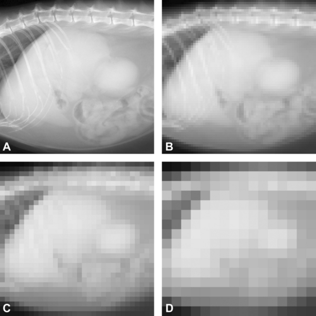
Figure 22-8 The effects of matrix and pixel size on image resolution are illustrated in this series of otherwise identical lateral cat abdominal radiographic images. A, A high-quality digital image with a high matrix size (e.g., 2048 pixels on the vertical axis × 2048 pixels across the horizontal axis). B, The matrix size is reduced to 64 × 64 pixels. Note that individual pixels can be seen as small squares, and the image has a pixilated appearance. C, The pixilation becomes noticeably worse when the matrix size is reduced to 32 × 32. D, The matrix size is only 16 × 16 pixels, and the image of the cat abdomen is no longer recognizable. Note that each pixel only represents a single shade of gray, dependent on bit number.
It should be intuitive that the smaller the pixel, the better image resolution (think of a photograph made using 1000 ASA film versus one made with 100 ASA; the 1000 ASA photograph is grainy when compared with the 100 ASA photo). Pixel size is determined by the size of the image divided by matrix size. As an example, if a thoracic image is 35 cm (roughly 14 inches) × 43 cm (17 inches) and the matrix size is 2000 × 2500, pixel size would be approximately 0.17 mm × 0.17 mm. Pixel size determines spatial resolution, the ability to separate two closely spaced objects. Actual spatial resolution of the digital image is further determined by the efficiency of the imaging plate and other design criteria.
VIEWING DIGITAL IMAGES
Display Monitors
All diagnostic review of digital images should be made through a high-quality display monitor. The ability of the viewer to appreciate the image quality obtained with digital radiography depends largely on the quality of the computer monitor.
Important considerations when assessing viewing station monitors include screen size, resolution, brightness, and gray-scale versus color capabilities. Although waning in popularity, the oldest and most familiar type of monitor is the cathode ray tube (CRT), which is similar to the picture tube in a conventional television set and uses an “electron gun” to illuminate each pixel. CRT monitors can be gray scale (“black and white”) or color. Gray-scale monitors have a greater dynamic range (are brighter) than color CRT monitors and can yield higher resolution. This is because there is only one electron gun per monitor pixel. Conversely, a color monitor has a red, green, and blue electron gun for each pixel; therefore the pixels are larger. Although a color monitor is not necessary for digital radiography, it is necessary for viewing color Doppler ultrasound images and useful for nuclear medicine image viewing as well. Flat panel monitors use liquid crystal display technology (LCD) and have become popular over the past several years, superseding the CRT because of lower cost and smaller size (depth).
As an example, a high-resolution, diagnostic, gray-scale, 20-inch monitor may have 2048 × 1536 pixels (known as 3-megapixel), while a high-quality, color, 19-inch diagnostic monitor may have a matrix size of 1600 × 1200. Note that these monitors offer a matrix size that is smaller than that of many digital image receptors. Medical-grade, gray-scale monitors are expensive ($10,000 or more), while high-quality color monitors are one-tenth this price. Vendors of digital radiography equipment often prefer a particular brand of monitor.
Film and Paper
Alternatively, diagnostic hard-copy images can be made by printing to a high-quality laser film (transparent film that resembles standard radiographic film), viewed using an illuminated view box. Use of film-based digital imaging in place of a computer diagnostic workstation viewing counteracts one of the primary advantages of digital imaging (i.e., going filmless). Nondiagnostic-quality paper images can be made to print out digital images for record keeping purposes.
TYPES OF DIGITAL RADIOGRAPHY (DR)
Digital receptors are generally classified as indirect or direct digital conversion systems. Indirect systems use a two-part process, converting x-ray energy first to light and then to an electronic (digital) signal. The indirect digital systems include photostimulable phosphor (PSP) imaging plates (used in CR), CCDs, and silicon flat panel receptors. Direct systems convert x-ray energy directly into an electrical (digital) signal. Using selenium detectors, these are correctly referred to as direct digital radiography systems (DDRs). DDRs are not commonly used even in human medicine due to great manufacturing costs. However, they yield the highest spacial resolution currently available.
Three principle types of digital image receptors are available to veterinarians: CR, flat panel detectors, and the CCD.
COMPUTED RADIOGRAPHY
CR was introduced to the medical community in the 1980s by Fujifilm Medical Systems. Although it has become common in human medicine over the past 20 years, CR has only recently been introduced to the veterinary community. Idexx markets a CR system designed for veterinary use. Agfa, Fuji, and Kodak are major human medical CR manufacturers that have shown an interest in the veterinary market.
CR is the term for digital imaging systems using a phosphostimulable phosphor (PSP) detector screen. The PSP screen absorbs and stores most of the incident x-ray energy (latent image), which is to be “read out” later. Because PSP screens store energy, they are also known as storage phosphors or CR imaging plates. By contrast, conventional screen-film intensifying screens do not store energy. Instead, they emit light instantaneously upon x-ray interaction, in turn exposing the radiographic film (latent image production), which is later developed into a radiograph.
PSP screens are composed of several layers—an outer protective layer, a phosphor layer (active component of system), a polyester support layer, a conductive layer (grounds plate to eliminate electrostatic interference and absorbs light, increasing image sharpness), and a light shield layer (prevents visible light from erasing data). The phosphor layer of a PSP screen is a barium fluorohalide phosphor composition (BaFlBr and BaFI).
The CR system can be thought of as using a filmless cassette. The PSP screens are thin, rigid yet flexible layered sheets (10 × 12, 14 × 17) and fit into a cassette, nearly identical to conventional screen-film cassettes. CR cassettes are used identically to conventional screen-film cassettes, placed on a tabletop or in a cassette (“Bucky”) tray for under-table use, with or without a grid. One PSP imaging plate is used per exposure. Following exposure, the CR cassette is taken to a laser CR reader unit (also known as an Image Reader Device [IRD], “CR processor,” or plate reader, among others) for processing the latent image.
The following occurs after exposure of the CR cassette:
CR readers vary in speed of processing. The simplest CR readers require the user to actually remove the CR plate and place it into the CR reader (a process similar to a fax or photocopy machine). The most robust units allow multiple CR cassettes to be “stacked,” automatically feeding, processing, and ejecting each CR cassette following reading and erasing. The CR reading process is analogous to an automatic x-ray film processor used with conventional screen-film systems. Thus there is little or no time savings of CR over screen-film systems from an image development point of view. CR is well-suited for equine radiography as the cassettes are portable.
The digital image is stored temporarily on a local or dedicated hard disk. As local storage is limited (several thousand images), digital images must ultimately be transferred to permanent storage in a larger-capacity computer or PACS if they are to be stored and archived digitally. Alternatively, “hard copy” can be made. Most common is film (similar in look and feel to a conventional radiograph), but images may be printed on paper (for archival purposes only, not for diagnosis).
Other Computed Radiography Considerations
PSP screens maximally absorb x-rays in the 35 to 50keV range, due to the barium k-edge. This is lower than conventional rare earth screen film systems. Below and above this range, however, absorption is inferior to rare earth systems and therefore more exposure may be necessary when using CR systems compared with 400-speed, screen-film systems.
The latent image is formed by attenuation of x-ray energy within the PSP plate, stored as light. Although PSP plates do release some light during x-ray exposure (i.e., they are not 100% efficient in capturing energy), enough energy remains to form a latent image. The latent image is converted to a digital image for computer storage and display. It should be noted that the latent image is temporary, losing 25% or more of its energy within 8 hours. Therefore CR cassettes must be processed in a timely manner, preferably within several hours of exposure. Also, because of their sensitivity to secondary radiation, they must be stored carefully and should routinely be “erased” before use. This is essential if CR plates have not been used for 24 hours or more. Failure to do so will result in artifacts and reduced signal-to-noise from spurious exposure.
CHARGED COUPLED DEVICE
A CCD is a small flat panel device that is capable of creating images from visible light. A CCD receives and stores incoming light energy in the form of trapped electrons. The CCD chip is an integrated circuit (IC) composed of crystalline silicon. It is photosensitive and divided into thousands of tiny electronically isolated pixels etched into its surface (e.g., a 1024 × 1024 or 2048 × 2048 matrix). Because of this, the CCD may be referred to as a pixilated light detector. CCD technology has been used for a number of years in digital camera and video recorder applications. When used in a digital radiology system, the CCD is coupled to a rather conventional rare earth or CsI intensifying (scintillation) screen. When the intensifying screen fluoresces following interaction with x-rays, the CCD captures this emitted light and stores the energy in the form of “trapped” electrons within each pixel. Once exposed, stored electrons are “read out” and converted from an analog electrical signal to a digital signal by an analog to digital converter (ADC).
One of the primary limitations of CCD technology is the size restriction of the chip, dictated by manufacturing obstacles and expense. CCD chips may be quite small (2.5 cm × 2.5 cm for digital dental applications), while the largest detectors are only 8 × 8 cm or so (and expensive). Small CCD chips can be directly coupled to the intensifying screen, with excellent transfer of light energy and radiographic image formation. However, larger areas such as the abdomen or thorax require a much larger field of view (FOV), considerably greater than the size of even the largest CCD currently available. To produce a real-size image, a high-quality focusing lens is used to couple a large intensifying screen (14 × 17 inches, or 35 × 43 cm) onto a considerably smaller CCD (this is termed demagnification factor).
Use of a coupling lens results in a substantial loss (>90%) of light energy reaching the CCD. The resultant radiographic image is degraded by a grainy appearance, a result of quantum mottle. Recall that quantum mottle occurs when there is insufficient number of photons to produce a quality image. These have been the limiting factors in the use of CCD technology for digital radiography, especially in cost-effective veterinary applications. Nonetheless, veterinary-specific systems are now marketed.
The CCD hardware is located under the tabletop of the x-ray machine, completely out of sight (Fig. 22-9). Most of the available systems are packaged as complete systems (with x-ray tube, generator, electronics, and table), though retrofitting a conventional x-ray system is possible. A CCD digital system is not suitable for ambulatory use, as the equipment is not portable.
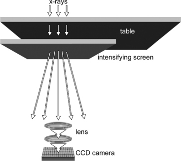
Figure 22-9 Illustration of the components of a charged coupled device (CCD) digital x-ray system. An intensifying screen is placed underneath the x-ray table and coupled to the CCD via focusing mirrors. Notice the etched pixel matrix on the surface of the relatively small CCD device. NOTE: The “camera portion” of the CCD is not shown.
Several manufacturers in the human imaging field producing high-quality, CCD-based digital radiography units (e.g., Swissray). Although offering state-of-the-art performance, this high-end equipment is usually not cost effective for most private veterinary practices. Currently available veterinary CCD digital radiography systems include dental systems and systems designed for a small animal radiology suite. Veterinary specific manufacturers include Summit and HCMI.
FLAT PANEL DETECTORS
Large, full-size flat panel detectors have become popular over the past several years. They consist of a large (e.g., 10- × 12-inch or 14- × 17-inch) x-ray intensifying screen (cesium iodide or gadolinium and lanthanum oxysulfide scintillators) that is intimately coupled to an amorphous silicon flat panel serving as the light detector (photodiode).
Flat panel detectors are analogous to conventional screen film systems, but an electronic sensor layer, amorphous silicon, replaces x-ray film. The silicon detector consists of a matrix, composed of a large number of individual detector elements (Fig. 22-10). Each detector element is in turn composed of a light sensitive area and a smaller area of electronics, the ratio of which is termed “fill factor.” Because each detector is an independent element, amorphous silicon detectors are more efficient and less susceptible to manufacturer imperfections than CCD technology.
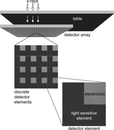
Figure 22-10 Illustration of the components of a flat panel detector system. The complete detector panel is located underneath the tabletop. A close-up view of a section of detector elements and of an individual active pixel element is shown. The panel is composed of a matrix of these pixels (e.g., 2208 × 2688).
Because the flat panel is a self-contained unit, it can be used for portable work (e.g., equine radiography) or permanently fixed beneath the x-ray tabletop for use in small animal radiology suites. The flat panel detector is hard-wired to the digital computer, which makes its use less flexible than CR for equine or field radiography. Current flat panel digital x-ray systems marketed for veterinary use include Eklin and Sound Technologies.
Because the flat panel is a self-contained unit, it can be used for portable work (e.g., equine radiography) or permanently fixed beneath the x-ray tabletop for use in small animal radiology suites. The flat panel detector is hard-wired to the digital computer, which makes its use less flexible than CR for equine or field radiography. Current flat panel digital x-ray systems marketed for veterinary use include Eklin and Sound Technologies.
Digital Artifacts
The advent of digital radiography has brought forth a whole new set of unique imaging artifacts. Although not within the scope of this chapter to fully describe and illustrate them, the interested reader is referred to the bibliography for further information.
Image plate artifacts.
CR image plates are susceptible to cracking as they bend inside the plate reader. Cracks occur first along the edges of the plate and progress centrally to interfere with the image. Cracks are areas without PSP and therefore show as white lines or “cracks” on the CR image. Debris within the CR cassette such as dirt or hair will block light and also appear as a sharp area of “white” image void. The latter is analogous to dirt within a conventional screen-film cassette. These white linear artifacts could be confused with a foreign body within the patient if not recognized.
Plate reader artifacts are caused when the CR plate has been improperly erased or not used for periods of 24 hours or longer. Ghost images from extraneous radiation from scatter radiation, “cosmic rays,” etc. can cause a type of CR image fogging. This is why CR plates must be erased before use if they have been stored for prolonged periods (>24 hours). Flat panel detectors are less sensitive but not immune to ghost image artifacts.
Imaging processing artifacts.
A number of operator-dependent imaging processing procedures can create artifacts if not applied properly. An example of this is a commonly encountered radiolucent “halo” around metallic orthopedic implants that can mimic implant infection and loosening. This is termed the Uberschwinger or rebound effect and occurs when the density of adjacent objects is significantly different (Figs. 22-11 and 22-12). Another example is a thoracic radiograph with extreme contrast that mimics lung pathology due to exaggerated edge enhancement (Fig. 22-13). Image processing parameters and application are CR manufacturer dependent. Image processing is a specific area of training that users of a new CR system should embrace.
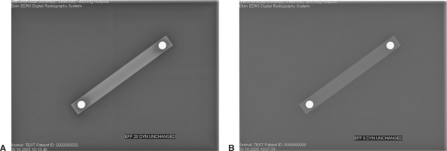
Figure 22-11 Uberschwinger artifact. This acrylic bar with metal ball bearings placed precisely 10 cm center to center is used to illustrate the Uberschwinger artifact. A, The large dark “halo” around the ball bearings is an artifact due to digital image processing. Image processing included an “Effects” (EFF) setting of 20 and a “Dynamic Range” (DYN) of 15 (UNCHANGED) B, The dark “halo” is no longer present following digital image manipulation. In this example the EFF was reduced to 0 and the DYN value was UNCHANGED at 15, eliminating the artifact.
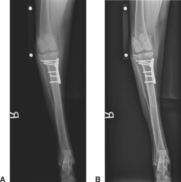
Figure 22-12 Clinical utility of recognition of the Uberschwinger artifact. A, The caudocranial radiographic image of this healed tibial plateau leveling osteotomy procedure shows apparent bone lysis surrounding the tips of the bone screws and underneath the distal portion of the bone plate. B, Following proper image processing, the artifactual “lysis” is gone, indicating that the orthopedic implants are not loosening.
OTHER OPERATOR ERRORS
Many operator errors mirror those made using conventional screen-film systems such as putting the CR plate upside down (the back of the CR plate is superimposed on the primary image) (Fig. 22-14) or misaligning the grid and causing grid cut-off or moiré lines (Fig. 22-15). Severe overexposure is possible even with digital radiography, to the point that processing cannot alleviate the artifacts (Fig. 22-16). Overexposure should be avoided at all costs.
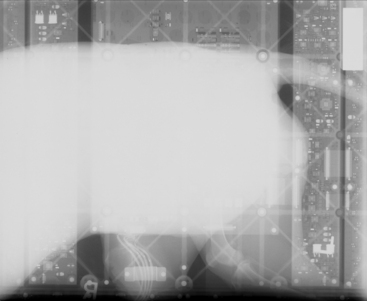
Figure 22-14 Operator error artifact. This image was made when a conventional screen-film cassette was placed in the cassette tray underneath a flat panel detector and a radiographic exposure was made. The electronics of the flat panel detector can be seen in addition to an underexposed, faintly visible (underexposed) lateral dog abdominal image. Imagine the surprise of the radiology technologist when this radiograph was placed on the view box!
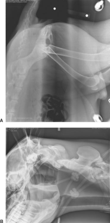
Figure 22-15 Grid malalignment (cut-off) artifacts. A, Can you recognize the central dark black stripe artifact? This digital artifact was caused by an upside-down grid. The identical artifact can occur with screen-film radiography. B, Grid lines due to lateral decentering of the grid. This artifact can also occur when the digital radiography “Grid on” program is not activated. With “Grid on,” a computer program recognizes the repeating grid lines and “eliminates” them from the image.
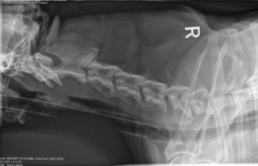
Figure 22-16 Severe overexposure has caused the trachea, endotracheal tube, portions of the hyoid bone, and the cervical soft tissues to “fade away” and become black in this lateral cervical image taken during myelography. A black “halo” also exists around the periphery of the dog where the skin is “burned out.” This degree of overexposure cannot be corrected at the digital workstation, and the exposure must be repeated. These errors should rarely, if ever, occur once a digital technique chart has been established.
X-RAY EXPOSURE FACTORS AND DOSE CONSIDERATIONS
Veterinarians must develop new technique charts for their digital systems on the basis of the manufacturer’s guidelines because digital and screen-film have different characteristics and it cannot be assumed that the exposure techniques used for screen-film will be optimal for digital imaging. Because of the greater latitude in exposure factors, digital technique charts are greatly simplified when compared with those used for conventional screen-film systems.
Most digital x-ray systems are not as efficient as a conventional 400-speed screen film system and therefore require an increase in radiation exposure to produce comparable images. Although direct comparison is difficult, most available digital systems can be compared with 200- to 300-speed screen film systems. This is countered with a reduced number of retake radiographic images from exposure errors, essentially eliminated with digital radiography. High radiation doses to both the patient and the radiology technician from overt overexposure are among the potential dangers when using digital radiography, perhaps not recognized because overexposed images can be corrected by computer manipulation, unlike a conventional radiograph. Purposeful overexposure “to be on the safe side” is irresponsible. The “as low as reasonably achievable” principle dictates that overt overexposures cannot be tolerated due to patient and technician exposure to radiation.
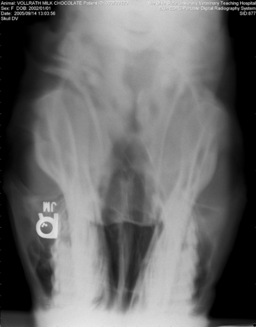
Figure 22-17 Motion artifact. Blurring of this dorsoventral image of a horse skull was caused by head movement during the radiographic exposure. Note that the “R” marker is not blurred; this is because the leaded marker has been placed on the stationary image detector.
Bushberg JT, et al. The essential physics of medical imaging. Philadelphia: Lippincott Williams & Wilkins, 2002.
Carlton RR, Adler AM. Principles of radiographic imaging, ed 3. New York: Delmar, 2001.
Cesar LJ, et al. Artefacts found in computed radiography. Br J Radiol. 2001;74:195-202.
Don S, et al. Computed radiography versus screen-film radiography: detection of pulmonary edema in a rabbit model that stimulates neonatal pulmonary infiltrates. Radiology. 1999;213:455-460.
Greene RE, Oestmann J. Computed digital radiography in clinical practice. New York: Thieme Medical Publishers, 1992.
Hruby W, editor. Digital (r)evolution. New York: Springer-Verlag, 2001.
Launders J. Digital x-ray systems, part 1: health devices: an introduction to DX technologies and an evaluation of cassette DX systems. Health Devices. 2001;30(8):273-310.
Lund PJ, et al. Comparison of conventional and computed radiography: assessment of image quality and reader performance in skeletal extremity trauma. Acad Radiol. 1997;4(8):570-576.
McLear RC et al: “Uberschwinger” or “rebound effect” artifact in computed radiographic imaging of metallic implants in veterinary medicine. In American College of Veterinary Radiology 2003 Annual Scientific Conference Proceedings, December 2-6, 2003, Chicago.
Murphey MD, et al. Nondisplaced fractures: spatial resolution requirements for detection with digital skeletal imaging. Radiology. 1990;174(3 Pt 1):865-870.
Ogoda M. DICOM 101. Understanding the basics of DICOM. Insights & images: the user’s publication of computed radiography. Stamford, Conn: Fujifilm Medical Systems, 2001.
Reiner B, et al. Evaluation of soft-tissue foreign bodies: comparing conventional plain film radiography, computed radiography printed on film, and computed radiography displayed on a computer workstation. Am J Roentgenol. 1996;167(1):141-144.
Roberts G, Graham J. Computed radiography. In: Kraft S, Roberts G, editors. Vet Clin North Am Equine Pract: Modern Diagnostic Imaging. Philadelphia: WB Saunders, 2001.
Roberts G: Computed radiography: how it works and its advantages. The AAEP 2000 Resort Symposium Lecture Workbook, February 4-6, 2000.
Seigel EL, Kolodner RM, editors. Filmless radiology. New York: Springer-Verlag, 1999.
Swee RG, et al. Screen-film versus computed radiography imaging of the hand: a direct comparison. Am J Roentgenol. 1997;168(2):539-542.
Wegryn SA, et al. Comparison of digital and conventional musculoskeletal radiography: an observer performance study. Radiology. 1990;175(1):225-228.
All Pets Dental. Why Radiology? http://www.dentalvet.com/vets/basicdentistry/whywhenhow_radiology.htm.
http://www.animalinsides.com Animal Insides: http://www.animalinsides.com
http://www.eklin.com Eklin Medical Systems, Inc: http://www.eklin.com
http://www.fujimed.com Fujifilm Medical Systems: http://www.fujimed.com
http://www.hcmixray.com HCMI: http://www.hcmixray.com, http://www.excelmedical.ca/digivet.htm
http://www.idexx.com/animalhealth/digital IDEXX Laboratories: http://www.idexx.com/animalhealth/digital
http://www.kodak.com/global/en/health Kodak: http://www.kodak.com/global/en/health/productsByType/cr/crVet_Product.jhtml?pq-path=7630
http://www.innovet4vets.com Summit Innovet: http://www.innovet4vets.com, http://www.imagingdynamics.com
http://www.swissray.com Swiss Ray: http://www.swissray.com