Chest and Abdomen
Chest: Posteroanterior Projection
Chest: Lateral Projection (Left Lateral Position)
Chest: Anteroposterior Projection (Supine or With Mobile X-Ray Unit)
Chest: Anteroposterior or Posteroanterior Projection (Right or Left Lateral Decubitus Position)
Chest: Anteroposterior Axial Projection (Lordotic Position)
Chest: Posteroanterior Oblique Projection (Right Anterior Oblique and Left Anterior Oblique Positions)
Neonate and Infant Chest: Anteroposterior Projection
Child Chest: Posteroanterior and Anteroposterior Projections
Neonate and Infant Chest: Cross-Table Lateral Projection (Left Lateral Position)
Child Chest: Lateral Projection (Left Lateral Position)
Neonate and Infant Chest: Anteroposterior Projection (Right or Left Lateral Decubitus Position)
Child Chest: Anteroposterior and Posteroanterior Projection (Right or Left Lateral Decubitus Position)
Abdomen: AP Projection (Supine and Upright)
Abdomen: Anteroposterior Projection (Left Lateral Decubitus Position)
Neonate and Infant Abdomen: Anteroposterior Projection (Supine)
Neonate and Infant Abdomen: Anteroposterior Projection (Left Lateral Decubitus Position)
Child Abdomen: Anteroposterior Projection (Left Lateral Decubitus Position)
After completion of this chapter, you should be able to do the following:
• Identify the required anatomy and describe the proper setup procedures for adult and pediatric chest and abdomen projections. Explain why each procedural step is required.
• State the technical data, marking and displaying requirements for chest and abdomen projections.
• List the image analysis requirements for accurately positioned adult and pediatric chest and abdomen images.
• State how to reposition the patient properly when chest and abdomen projections with poor positioning are produced.
• State how to position the patient and central ray to demonstrate air and fluid levels within the pleural cavity and when to expose chest images when the patient is unconscious or on a ventilator to obtain a fully aerated lung.
• State the purpose and proper location of the internal devices, tubes, and catheters demonstrated on adult and pediatric chest and abdomen images.
• Describe how the chest dimensions change when the patient breaths and discuss how to determine whether full lung expansion is obtained on chest images.
• Describe methods of identifying hemidiaphragms on chest images.
• State why the kilovoltage peak (kVp) level used for mobile chest images is lower than that for routine chest images. Discuss why a different kVp level is used when an image is taken to evaluate the patient's lung field versus the mediastinal region.
• Discuss how the patient is specifically positioned to rule out pneumothorax and pleural effusion on chest images.
• Explain how neonates' lungs develop and change as they grow.
• Discuss how technique is adjusted for imaging of the abdomen of patients with various abdominal conditions.
The following image analysis criteria are used for all adult and pediatric chest projections and should be considered when completing the analysis for each chest projection presented in this chapter (Box 3-1).
Visibility of Chest Details
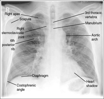
Beam penetration, contrast, and density are sufficient on chest images when the thoracic vertebrae and posterior ribs are faintly seen through the heart shadow and mediastinal structures, the vascular lung markings throughout the lung field and the soft tissue outlines of the air-filled trachea are visible, and fluid level or air within the pleural cavity and internal devices, tubes, and catheters, when present, are demonstrated.
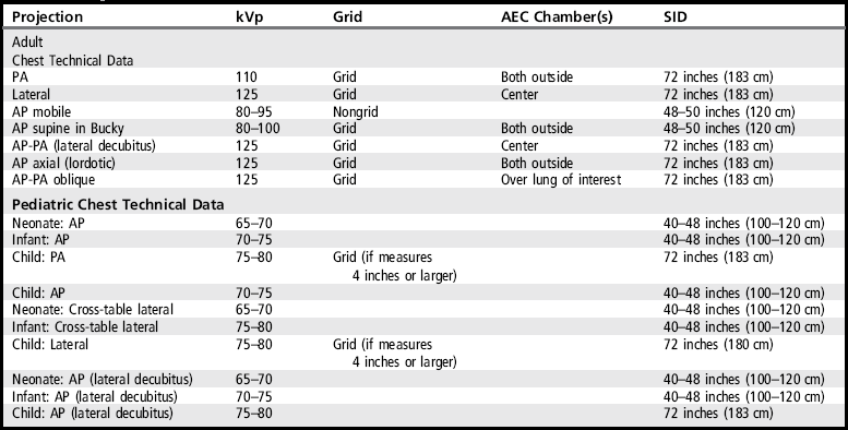
An optimal kilovoltage peak (kVp) technique, as shown in Table 3-1, sufficiently penetrates the chest structures and provides the contrast scale necessary to visualize the lung details. To obtain optimal density, set milliampere-seconds (mAs) manually based on the patient's thorax thickness or choose the appropriate automatic exposure control (AEC) chamber when recommended (see Table 3-1). A grid is used in adult chest imaging, with the exception of mobile imaging, for which a grid is not commonly used because it is difficult to ensure that the grid and central ray are aligned accurately enough to prevent grid cutoff. When no grid is used, a lower kVp technique is needed to prevent excessive scatter radiation from reaching the IR and hindering contrast. Although the lower kVp will sufficiently penetrate the lung field, it seldom provides enough penetration to visualize structures within and behind the heart shadow fully.
Vascular Lung Markings
Vascular lung markings are scattered throughout the lungs and are evaluated for changes that may indicate pathology. To visualize these markings on chest images, the lungs must be fully expanded. To obtain maximum lung aeration in a patient who is able to follow instructions, take the exposure after the second full inspiration. For the unconscious patient, observe the chest moving and take the exposure after the patient takes a deep breath.
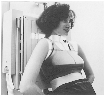
Ventilated Patient
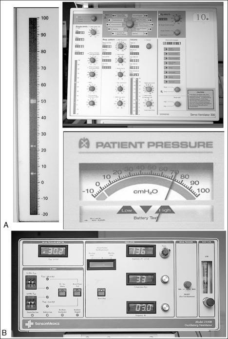
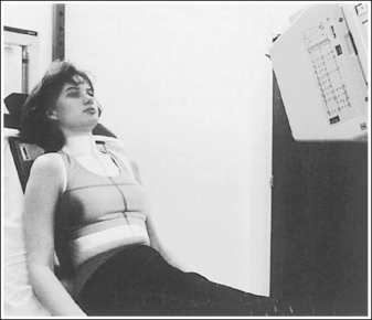
For the patient who is being ventilated with a conventional ventilator, observe the ventilator's pressure manometer (Figure 3-1, A). The exposure should be taken when the manometer digital bar or analog needle moves to its highest position. If a high-frequency ventilator is being used, the exposure may be made at any time, because this ventilator maintains the lung expansion at a steady mean pressure without the bulk gas exchange of the conventional type (see Figure 3-1, B).
Lung Conditions Affecting Vascular Lung Marking Visualization
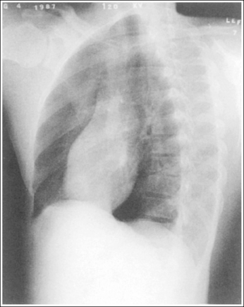
A pneumothorax (Figure 3-2) or pneumectomy (Figure 3-3) may be indicated if no lung markings are present, whereas excessive lung markings may suggest conditions such as fibrosis, interstitial or alveolar edema, or compression of the lung tissue. When selecting the technical factors (mAs and kVp) to be used for chest imaging, if a pneumothorax is suspected, decrease the kVp 8% from the routinely used setting (see Table 3-1). When a pneumectomy is indicated, do not select the AEC chamber that is positioned beneath the removed lung or overexposure will result (see Image 1).
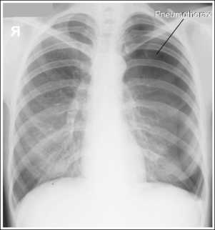
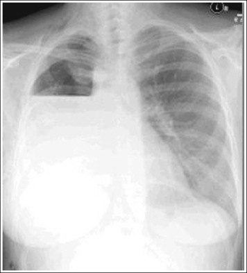
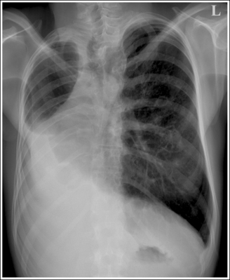
Image 1
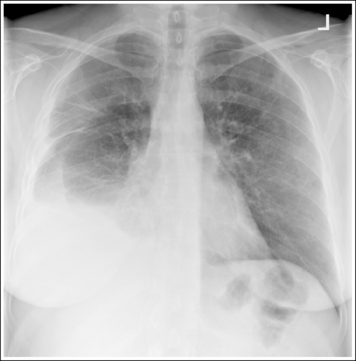
Fluid Levels and Air
To demonstrate precise fluid levels when a pleural effusion is suspected, chest images are taken with the patient upright and the x-ray beam horizontal. With this setup the air rises and the fluid gravitates to the lowest position, creating an air-fluid line or separation. This separation can be identified as a decrease in density on the image wherever the denser fluid is present in the lung field (Figures 3-4 and 3-5). If the patient is positioned only partially upright, the fluid line will slant, like water in a tilted jar. To demonstrate the true fluid line in a slanted position, the central ray must remain horizontal, which will result in foreshortening of the chest structures in the AP and PA projections. If the central ray is angled with the patient for a true AP-PA projection, the true amount of fluid cannot be discerned. When the patient is supine, the fluid is evenly spread throughout the lung field, preventing visualization of fluid levels in the AP projection because a horizontal beam cannot be used. If pleural effusion is suspected, increase the mAs by 35% over the routinely used setting (see Table 1-3).
Table 3-2
Chest Devices, Tubes, and Catheters
| Device, Tube, or Catheter | Desired Location | Image Density and Penetration to Visualize |
| Endotracheal tube (ETT) | Distal tip is placed 1–2 inches superior to carina when patient's neck is in neutral position | Upper mediastinal region |
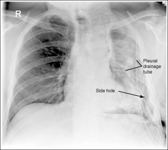
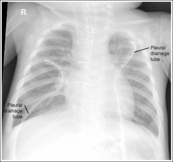
| Pleural drainage tube (chest tube) | Fluid drainage–located laterally within pleural space at level of the fifth or sixth intercostal space Air drainage—located anteriorly within pleural space at level of midclavicle |
Radiopaque identification line and side hole interruption |
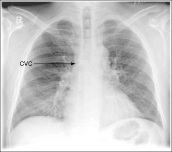
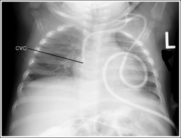
| Central venous catheter (CVC) | Inserted into subclavian or jugular vein and extends to superior vena cava, about 2.5 cm above right atrial junction | CVC within heart shadow |
| Umbilical artery catheter (umbilical artery catheter [UAC]) | Inserted into umbilicus and coursed to midthoracic aorta (T6 to T9) or below level of renal arteries, at approximately L1 to L2 | UAC on lateral chest image adjacent to vertebral bodies |
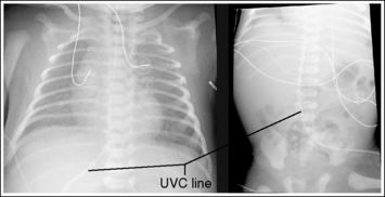
| Umbilical vein catheter (UVC) | Inserted into umbilicus and advanced to junction of right atrium and inferior vena cava | UVC from umbilicus to heart |
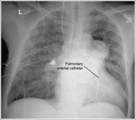
| Pulmonary arterial catheter | Inserted into subclavian, internal or external jugular, or femoral vein and advanced through right atrium into pulmonary artery | Catheter within heart shadow |
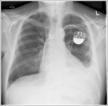
| Pacemaker | Internal pacemaker implanted in subcutaneous fat in anterior chest wall and catheter tip(s) directed to right atrium or right ventricle | Pacemaker in lateral thorax and catheter tip(s) within heart shadow |
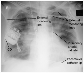
| Automatic implantable cardioverter defibrillator (ICD) | ICD is implanted in subcutaneous fat in anterior chest wall and catheter tip(s) directed to right atrium or right ventricle | ICD in lateral thorax and catheter tip(s) within heart shadow |
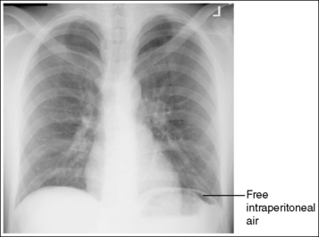
Free Intraperitoneal Air
The erect chest image is also an excellent method of discerning the presence of free intraperitoneal (within abdominal cavity) air because it will closely outline the diaphragm (Figure 3-6). As noted, the central ray must remain horizontal for the air to be demonstrated.
Internal Devices, Lines, and Catheters
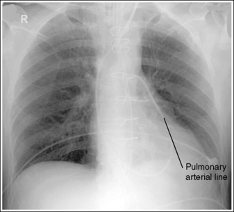
Familiarizing yourself with the accurate placement of the devices, lines, and catheters that are seen on chest images will provide the information needed to identify when proper technique was used to visualize them and when poor placement is suspected (Table 3-2). Figure 3-7 demonstrates poor placement of the pulmonary arterial line, because it was not advanced to the pulmonary artery. When a chest image is taken to determine the accuracy of line placement, it is within the technologist's scope of practice to inform the radiologist or attending physician immediately when a mispositioned device, line, or catheter is suspected.
Endotracheal Tube
The endotracheal tube (ETT) is a stiff, thick-walled tube used to inflate the lungs. For adults the distal tip of the ETT should be positioned 1 to 2 inches (3 to 5 cm) superior to the tracheal bifurcation (carina) when the neck is in a neutral position (Figure 3-8). For neonates, the ETT should reside between the thoracic inlet and carina, which is at the level of T4 on the neonate (Figure 3-9). With the distance from the thoracic inlet to the carina being minimal on a neonate, the position of this tube is critical to within a few millimeters.
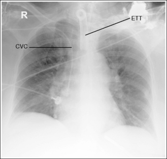
Figure 3-8 AP chest projection demonstrating accurate placement of an endotracheal tube (ETT) and central venous catheter (CVC).
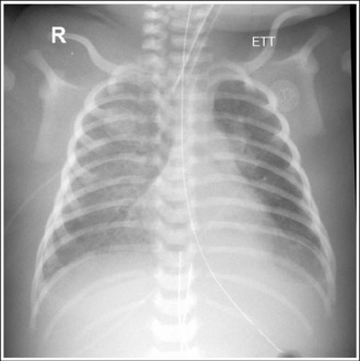
Figure 3-9 Neonate AP chest projection demonstrating accurate placement of an endotracheal tube (ETT).
When imaging for ETT placement, the patient's face should be facing forward and the cervical vertebrae in a neutral position. With head rotation and cervical vertebrae flexion and extension, the ETT tip can move superiorly and inferiorly, respectively, making it more uncertain whether the tube is positioned in the correct location. Too superior positioning of the tube may place it in the esophagus, and too inferior placement may place the tube in the right main bronchus, causing hyperinflation of the right lung and collapse of the left lung. Images taken for ETT placement should demonstrate penetration of the upper mediastinal region, and the longitudinal collimation should remain open to the bottom of the lip to include the upper airway.
Pleural Drainage Tube
The pleural drainage tube is a 1.25-cm diameter thick-walled tube used to remove fluid or air from the pleural space that could result in collapse of the lung. For drainage of air, the tube is placed anteriorly within the pleural space at the level of the midclavicle (Figures 3-10 and 3-11). For drainage of fluid, the tube is placed laterally within the pleural space at the level of the fifth or sixth intercostal space. The side hole of the tube is marked by an interruption of the radiopaque identification line. Images taken for pleural drainage tube placement should visualize the radiopaque identification line interruption at the side hole.
Central Venous Catheter
The central venous catheter (CVC) is a small (2- to 3-mm) radiopaque catheter used to allow infusion of substances that are too toxic for peripheral infusion, such as for chemotherapy, total parenteral nutrition, dialysis, or blood transfusions. The CVC is commonly inserted into the subclavian or jugular vein and extends to the superior vena cava, about 2.5 cm above the right atrial junction (Figures 3-12 and 3-13). Images taken for CVC placement should visualize the CVC and any lung condition that might result if tissue perforation occurred during line insertion, such as pneumothorax or hemothorax.
Pulmonary Arterial Catheter (Swan-Ganz Catheter)
The pulmonary arterial catheter is similar to the CVC catheter but it is longer. It is used to measure atrial pressures, pulmonary artery pressure, and cardiac output. The measurements obtained are used to diagnose ventricular failure and monitor the effects of specific medication, exercise, and stress on heart function. The pulmonary arterial catheter is inserted into the subclavian, internal or external jugular, or femoral vein and is advanced through the right atrium into the pulmonary artery (Figure 3-14). Images taken for pulmonary arterial catheter placement should visualize the catheter and mediastinal structures to determine adequate placement.
Umbilical Artery Catheter
The umbilical artery catheter (UAC) is found only in neonates, because the cord has dried up and fallen off in older infants. The UAC is used to measure oxygen saturation. Optimal location for the UAC is in the midthoracic aorta (T6 to T9) or below the level of the renal arteries, at approximately L1 to L2. On a lateral chest image, the UAC is seen to lie posteriorly adjacent to the vertebral bodies because it courses in the aorta.
Umbilical Vein Catheter
The umbilical vein catheter (UVC) is found only in neonates, because the cord has dried up and fallen off in older infants. The UVC is used to deliver fluids and medications. The UVC courses anteriorly and superiorly to the level of the heart. The ideal location of the UVC is at the junction of the right atrium and inferior vena cava (Figure 3-15).
Pacemaker
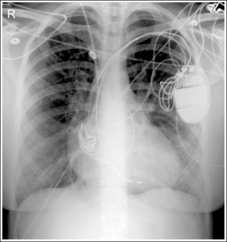
The pacemaker is used to regulate the heart rate by supplying electrical stimulation to the heart. This electrical signal will stimulate the heart the needed amount to maintain an effective rate and rhythm. The internal pacemaker is surgically implanted in the subcutaneous fat in the patient's anterior chest wall and the catheter tip(s) directed to the right atrium or the right ventricle. On a PA-AP chest projection the pacemaker is typically seen laterally and the catheter tip(s) is seen in the heart shadow (Figure 3-16). Because the pacemaker is inserted in the patient's upper thorax, care should be taken when lifting the patient's arm whose pacemaker was inserted within 24 hours of the examination, because elevation may dislodge the pacemaker and catheter.
Automatic Implantable Cardioverter Defibrillator
The implantable cardioverter defibrillator (ICD) is implanted in the anterior chest wall, as with the pacemaker, and the catheter tip(s) directed to the right atrium or the right ventricle. It is used to detect heart arrhythmias and then deliver an electrical shock to the heart to convert it to a normal rhythm. On a PA-AP chest projection the ICD is typically seen laterally and the catheter tip(s) is seen in the heart shadow (Figure 3-17).
External Monitoring Tubes and Lines
All external monitoring tubes or lines that can be removed or shifted out of the lung field should be. This includes oxygen tubing, electrocardiographic leads, external portions of nasogastric tubes, enteral feeding tubes, temporary pacemakers, and telemetry devices. Leaving these tubes and lines overlaying the lung field may result in obscuring important lung details (Figure 3-18).
CHEST: POSTEROANTERIOR PROJECTION
See Figure 3-19 and Box 3-2.
The seventh thoracic vertebra is at the center of the exposure field. Both lungs, from the apices to costophrenic angles, are included within the collimated field.
• Centering a perpendicular central ray to the midsagittal plane, at a level approximately 7.5 inches (18 cm) inferior to the vertebra prominens (seventh cervical spinous process), places the seventh thoracic vertebra in the center of the image. The seventh thoracic vertebra is identified on the image by counting down the vertebral column from the first thoracic vertebra, which is located just superior to the lung field and is the first vertebra that demonstrates rib attachment. This central ray placement also centers the lung field on the image. Center the image receptor (IR) to the central ray. Open the transversely collimated field to within 0.5 inch (2.5 cm) of the patient's lateral skin line. For most adult PA chest projections, the full IR length is needed, although you should collimate longitudinally on small patients.
• IR size and direction. A 14- × 17-inch (35- × 43-cm) IR should be large enough to include all the required anatomic structures. The direction of IR placement (crosswise versus lengthwise) must also be considered to ensure full lung coverage. For the average sthenic patient and hyposthenic and asthenic patients, whose lung fields are long and narrow, position the IR lengthwise. For the hypersthenic patient, whose lung fields are short and wide, position the IR crosswise.
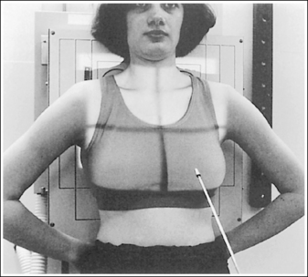
• Change in lung dimensions on inspiration. Along with body type, consider how the lung expands on deep inspiration when choosing IR placement (crosswise, lengthwise). On inspiration, the lungs expand in three dimensions—transversely, anteroposteriorly, and vertically. Evaluate the transverse and vertical dimensions to determine how the IR should be placed. When a patient takes a deep breath, will the costophrenic angles still be included on the image? Determine this by placing a hand along the patient's side at the level of the costophrenic angles, and then asking the patient to inhale. If your hands remain within the IR's boundaries on inspiration, the IR is wide enough to accommodate the patient. If your hands move outside the IR's boundaries on inspiration, consider placing the IR crosswise. It is the vertical dimension that will demonstrate the greatest expansion. During high levels of breathing, as when we coax a patient into deep inspiration for a chest image, the vertical dimension can increase by as much as 4 inches (10 cm). This full vertical lung expansion is necessary to demonstrate the entire lung field. Imaging the patient in an upright position and encouraging a deep inspiration by taking the exposure at the end of the second full inspiration allow demonstration of the greatest amount of vertical lung field. Circumstances that may prevent full lung expansion include disease processes, advanced pregnancy, excessive obesity, being seated in a slouching position, and confining abdominal clothing.
A PA projection is demonstrated. The distances from the vertebral column to the sternal (medial) ends of the clavicles are equal, and the lengths of the right and left corresponding posterior ribs are equal.
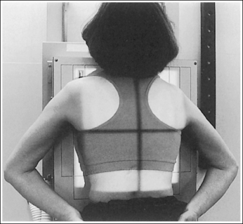
• To avoid chest rotation, position the patient's shoulders and arms at equal distances from the IR and instruct the patient to distribute body weight evenly on both feet and to face forward (Figure 3-20). Special attention should be given to female patients who have had one breast removed. The side of the patient on which the breast was removed may need to be placed at a greater object–image receptor distance (OID) than the opposite side to prevent rotation. A rotated chest image demonstrates distorted mediastinal structures and may create an uneven density between the lateral borders of the chest. This density difference occurs because the x-ray beam traveled through less tissue on the chest side positioned away from the IR than on the side positioned closer to the IR. It may be detected when the chest has been rotated as little as 2 or 3 degrees. Because any variation in structural relationships or density may represent a pathologic condition, the importance of providing nonrotated PA chest projections cannot be overemphasized.
• Detecting rotation. Rotation is readily detected on a PA chest projection by evaluating the distances between the vertebral column and the sternal ends of the clavicles and by comparing the lengths of the posterior ribs. On a nonrotated PA chest projection, these distances and lengths should be equal, respectively. On a rotated PA projection, the sternal clavicular end that demonstrates the least vertebral column superimposition and the side of the chest with the greatest posterior rib length represents the side of the chest positioned farthest from the IR (see Image 2).
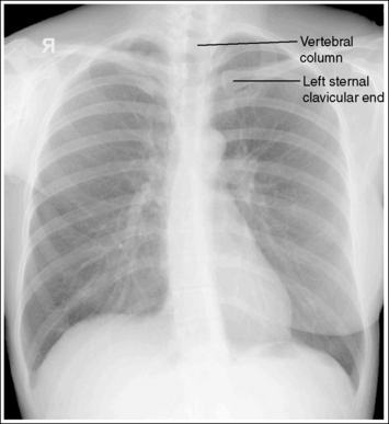
Image 2
• Distinguishing scoliosis from rotation. Scoliosis is a condition of the spine that results in the vertebral column's curving laterally instead of remaining straight. Scoliosis can be distinguished from rotation by comparing the distance from the vertebral column to the lateral lung edges down the length of the lungs. On images of a rotated patient, the distances are uniform down the length of the lung field, although when both lungs are compared, the distance is shorter on one side. If the patient has scoliosis, the vertebral column to lateral lung edge distances vary down the length of each lung and between each lung (see Image 3). The amount of distance variation increases with the severity of the scoliosis.
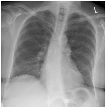
Image 3
Clavicles are positioned on the same horizontal plane.
• The lateral ends of the clavicles are positioned on the same horizontal plane as the medial clavicle ends by depressing the patient's shoulders. Accurate clavicle positioning lowers the lateral clavicles, positioning the middle and lateral clavicles away from the apical chest region and providing better visualization of the apical lung field. When a PA chest projection is taken without depression of the shoulders, the lateral ends of the clavicles are elevated, causing the middle and lateral clavicles to be demonstrated within the apical chest region (see Image 4).
Image 4
The humeri are abducted away from the chest, and the scapulae are located outside the lung field.
• Placing the back of the patient's hands on the hips draws the humeri away from the chest. This positioning also allows the patient easily to rotate the elbows and shoulders anteriorly to place the scapulae outside the lung field. When the scapulae are accurately positioned, the superolateral portion of the lungs is better visualized. If a chest image is taken without anterior rotation of the elbows and shoulders, the scapulae are seen superimposing the superolateral lung field (see Image 5).
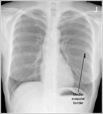
Image 5
• Scapular densities may prevent detection of abnormalities in the periphery of the lungs. Many dedicated chest units provide holding bars for the patient's arms. When using these units, make certain that the shoulders are protracted. If the patient is unable to protract the shoulders while using the bars, position the patient's arms as described earlier.
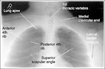
The manubrium is superimposed by the fourth thoracic vertebra, with approximately 1 inch (2.5 cm) of the apical lung field visible above the clavicles, and the lungs and heart are demonstrated without foreshortening.
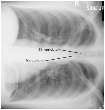
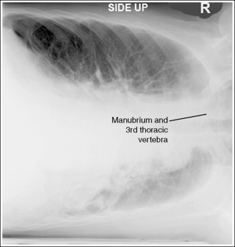
• The tilt of the midcoronal plane determines the relationship of the manubrium to the thoracic vertebrae, the amount of apical lung field seen above the clavicles, and the degree of lung and heart foreshortening. When the midcoronal plane is vertical, the manubrium is projected at the level of the fourth thoracic vertebra, approximately 1 inch (2.5 cm) of the apices is visible above the clavicles, and the lungs and heart are demonstrated without foreshortening. If the superior midcoronal plane is tilted anteriorly (forward), however, as demonstrated in Figure 3-21, the lungs and heart are foreshortened, the manubrium is situated at the level of the fifth thoracic vertebra or lower, and more than 1 inch (2.5 cm) of the apices is demonstrated above the clavicles (see Image 6). This positioning error most often occurs during imaging of women with pendulous breasts and patients with protruding abdomens. Conversely, if the superior midcoronal plane is tilted posteriorly (backward), as demonstrated in Figure 3-22, the lungs and heart are foreshortened, the manubrium is situated at a level between the first and third thoracic vertebrae, and less than 1 inch (2.5 cm) of the apices is demonstrated above the clavicles (see Image 7).
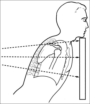
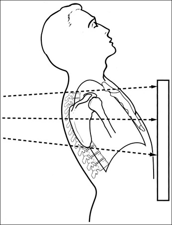
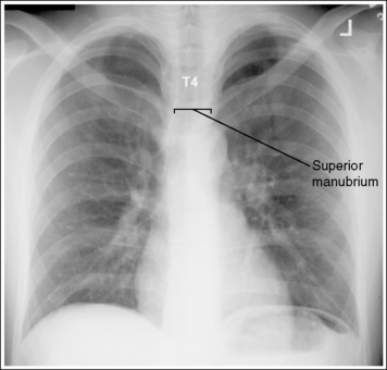
Image 6
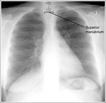
Image 7
• Poor midcoronal plane versus poor shoulder positioning. When a PA chest projection is taken with the patient's upper midcoronal plane tilted toward the IR, the clavicles are not always demonstrated horizontally but may be seen vertically (see Image 6). Distinguish poor shoulder positioning from poor midcoronal plane positioning by measuring the amount of lung field visualized superior to the clavicles and determining which vertebrae are superimposed over the manubrium. An image with poor shoulder positioning demonstrates decreased lung field superior to the clavicles and the manubrium at the level of the fourth vertebra. An image with the upper midcoronal plane tilting anteriorly demonstrates increased lung field superior to the clavicles and the manubrium at a level inferior to the fourth vertebra.
Ten or 11 posterior ribs are demonstrated above the diaphragm, indicating full lung aeration.
• To obtain maximum lung aeration, take the exposure with the patient in an upright position and after the second full inspiration. When the patient is positioned upright, the abdominal organs and diaphragm shift inferiorly, providing more space for maximum vertical lung expansion. If fewer than 10 posterior ribs are demonstrated, the lungs were not fully inflated. Before repeating the procedure, attempt to obtain a deeper inspiration and determine whether a patient's condition might have caused the poor inhalation. Chest images that are taken with inadequate inspiration may demonstrate a decrease in image density, because a decrease in air volume increases the concentration of pulmonary tissues and the heart shadow may appear larger than it actually is.
• Expiration chest image. Abnormalities such as a pneumothorax or foreign body may indicate the need for an expiration chest image. For such an image, all evaluation requirements listed for a PA chest projection should be met except the number of ribs demonstrated above the diaphragm. On an expiration chest image, as few as nine posterior ribs may be demonstrated, the lungs are denser, and the heart shadow is broader and shorter (see Image 8). When manually setting technique, it may be necessary to increase the exposure (mAs) when a PA chest projection is taken on expiration and lung details are of interest.
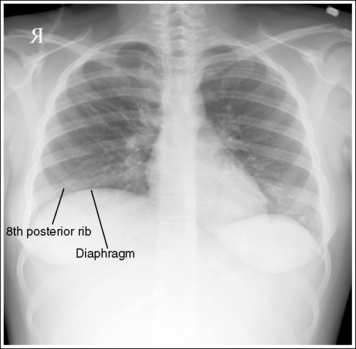
Image 8
Posteroanterior Chest Projection Analysis
The patient has a right-sided pneumectomy. The left lung was overexposed because the right AEC chamber was activated.
Analysis
The left sternal clavicular end is visualized without vertebral column superimposition, and the left posterior ribs demonstrate greater length than the right posterior ribs. The patient was slightly rotated, with the right side of the chest positioned closer to the IR than the left.
Correction
To offset chest rotation, position the left shoulder closer to the IR. The shoulders should be at equal distances from the IR.
Analysis
The distances from the vertebral column to the lateral rib edges down the length of lungs vary, indicating that the patient has scoliosis.
Analysis
The clavicles are not horizontal, and the lateral ends of the clavicles are elevated, obscuring the apices. The manubrium is situated at the level of the fourth thoracic vertebra, and approximately 1 inch (2.5 cm) of the apices is demonstrated superior to the clavicles, indicating that the midcoronal plane was adequately positioned. The patient's shoulders were not depressed.
Analysis
The medial borders of the scapulae are demonstrated within the superolateral lung field; the shoulders and elbows were not anteriorly rotated.
Analysis
The manubrium is situated at the level of the fifth thoracic vertebra, and more than 1 inch (2.5 cm) of the apices is demonstrated superior to the clavicles. The upper midcoronal plane was tilted anteriorly (see Figure 3-21).
Analysis
The manubrium is situated at the level of the second thoracic vertebra, and less than 1 inch (2.5 cm) of the apices is demonstrated superior to the clavicles. The upper midcoronal plane was tilted away from the IR (see Figure 3-22).
CHEST: LATERAL PROJECTION (LEFT LATERAL POSITION)
See Figure 3-23 and Box 3-3.
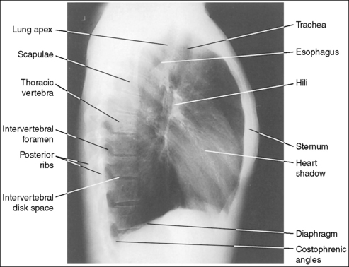
The midcoronal plane, at the level of the eighth thoracic vertebra, is at the center of the exposure field. The entire lung field, including apices, costophrenic angles, and posterior ribs, is included within the collimated field.
• Centering a perpendicular central ray to the midcoronal plane, at a level approximately 8.5 inches (21.25 cm) inferior to the vertebra prominens places the central ray at the level of the eighth thoracic vertebra. This lower centering, compared with that for the PA chest projection, is needed to include the right costophrenic angle on the image. Because the right costophrenic angle is positioned at a long OID and the central ray is centered superiorly to it, the costophrenic angle is projected inferiorly. Center the IR to the central ray.
• Positioning the midcoronal plane vertically prevents forward or backward leaning, which may result in clipping of the sternum or posterior ribs. Open the transversely collimated field to within 0.5 inch (1.25 cm) of the lateral skin line. For most adult lateral chest images, the full IR length is needed, although you should collimate longitudinally on small patients.
• A 14- × 17-inch (35- × 43-cm) lengthwise IR should be adequate to include all the required anatomic structures.
A lateral chest projection is demonstrated. The right and left posterior ribs are almost superimposed, demonstrating no more than a 0.5-inch (1-cm) space between them, and the sternum is in profile.
• To avoid chest rotation, align the shoulders, posterior ribs, and posterior pelvic wings perpendicular to the IR (Figure 3-24). This alignment is accomplished by resting an extended flat hand against each, respectively, and then adjusting the patient's rotation until the hand is positioned perpendicularly to the IR. Because the right lung field and ribs are positioned at a greater OID than the left lung field and ribs, the right lung field and ribs are more magnified. This magnification prevents the right and left ribs from being directly superimposed. Routinely, approximately a 0.5-inch (1-cm) separation is demonstrated between the right and left posterior ribs, with the right posterior ribs projecting behind the left. When the posterior ribs are directly superimposed, this separation is demonstrated between the anterior ribs, but it is more difficult to distinguish (see Image 9).
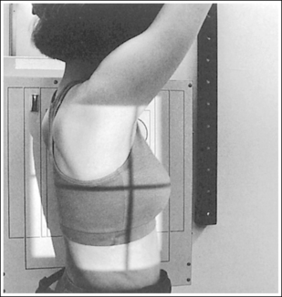
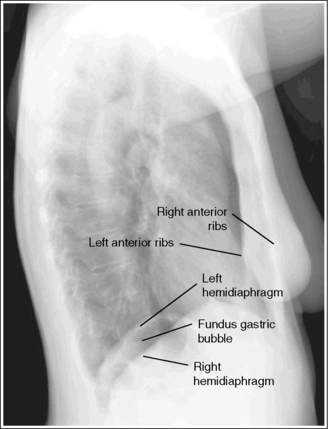
Image 9
• Detecting chest rotation. Chest rotation is effectively detected on a lateral chest projection by evaluating the degree of superimposition of the posterior ribs and anterior ribs. When more than 0.5 inch (1.25 cm) of space exists between the right and left posterior ribs, the chest was rotated for the image. A rotated lateral chest projection obscures portions of the lung field and distorts the heart and hilum shadows.
• Distinguishing the right and left lungs. When a rotated lateral chest projection has been obtained, determine how to reposition the patient by identifying the hemidiaphragms and therefore the lungs. The first and easiest method of discerning the hemidiaphragm is to identify the gastric air bubble. On an upright patient, gas in the stomach rises to the fundus (superior section of stomach), which is located just beneath the left hemidiaphragm (see Images 9 and 11). If this gastric bubble is visible on the image, you know that the left hemidiaphragm is located directly above it. The second method of distinguishing one lung from the other uses the heart shadow. Because the heart shadow is located in the left chest cavity and extends anteroinferiorly to the left hemidiaphragm, outlining the superior heart shadow enables you to recognize the left lung. As demonstrated in Figure 3-25, if the left lung is positioned anteriorly, the outline of the superior heart shadow continues beyond the sternum and into the anterior lung (see Image 10). Figure 3-26 demonstrates the opposite rotation; the right lung is positioned anteriorly. Note how the superior heart shadow does not extend into the anterior situated lung but ends at the sternum (see Image 11). It is most common on rotated lateral chest projections for the left lung to be rotated anteriorly and the right lung to be rotated posteriorly.
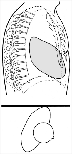
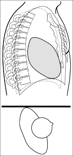
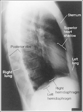
Image 10
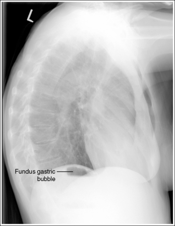
Image 11
• Repositioning the rotated patient. Once the lungs have been identified, reposition the patient by rotating the thorax. When the left lung was anteriorly positioned on the original image, rotate the left thorax posteriorly, and when the right lung was anteriorly positioned, rotate the right thorax posteriorly. Because both lungs move simultaneously, the amount of adjustment should be only half of the distance demonstrated between the posterior ribs.
• Distinguishing scoliosis from rotation. On images of patients with spinal scoliosis, the lung field may appear rotated because of the lateral deviation of the vertebral column (see Image 12). The anterior ribs are superimposed, but the posterior ribs demonstrate differing degrees of separation, depending on the severity of scoliosis. View the accompanying PA chest projection to confirm this patient condition. Although the separation between the posterior ribs is not acceptable beyond 0.5 inch (1.25 cm) on a patient without scoliosis, it is acceptable on a patient with the condition.
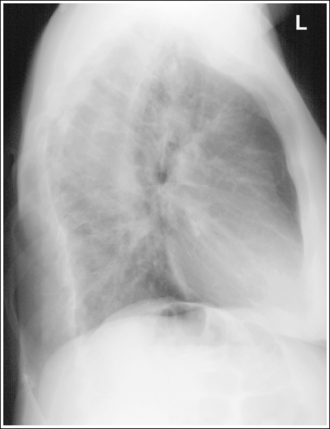
Image 12
The lungs are demonstrated without foreshortening, with almost superimposed hemidiaphragms.
• Lung foreshortening. To obtain a lateral chest projection without lung foreshortening, position the midsagittal plane parallel with the IR. When imaging a patient with broad shoulders and narrow hips, it is essential to place the hips away from the IR to maintain a parallel midsagittal plane. In 90% of persons the right lung and diaphragm are situated at a slightly higher elevation than the left lung and diaphragm. This elevation is caused by the liver, which is situated directly below the right diaphragm. Because the right diaphragm is elevated, one might expect it to be demonstrated above the left diaphragm when the patient is imaged from the side, but this is not true when the midsagittal plane is correctly positioned. Because the anatomic part positioned farthest from the IR diverges and magnifies the most, the right lung will be projected and magnified more than the left lung. The resulting image demonstrates near superimposition of the two hemidiaphragms. When the midsagittal plane has not been positioned parallel with the IR, lung foreshortening and poor hemidiaphragm positioning occur.
• Poor midsagittal plane positioning. Figure 3-27 demonstrates a lateral chest projection obtained with the patient's shoulders and hips resting against the IR, causing the inferior midsagittal plane to tilt toward the IR. This positioning projects the right hemidiaphragm inferior to the left on the image (see Image 13). When such an image has been obtained, determine how the patient was mispositioned by using one of the methods described earlier to distinguish the right lung from the left lung. Before retaking a lateral chest projection because of foreshortening, scrutinize the patient's accompanying PA projection to determine whether the patient is one of the 10% of those whose hemidiaphragms are at the same height or whether a pathologic condition is causing the left hemidiaphragm to be projected above the right (Figure 3-28).
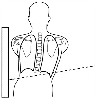
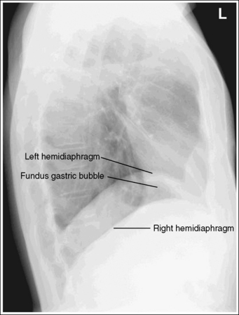
Image 13
• Right versus left position. A lateral chest projection obtained with the left side versus the right side of the chest positioned against the IR will demonstrate two distinct differences, the size of the heart shadow and the superimposition of the hemidiaphragms. Both differences are a result of a change in OID and magnification. A lateral chest projection taken with the right thorax positioned closer to the IR will demonstrate the anatomic structures located in the left thorax with greater magnification than structures located in the right thorax. Radiographically, the heart shadow will be more magnified and the left hemidiaphragm will project lower than the right hemidiaphragm (see Image 14). One advantage of obtaining the lateral chest projection with the right thorax closer to the IR is that it will demonstrate increased right lung radiographic detail.
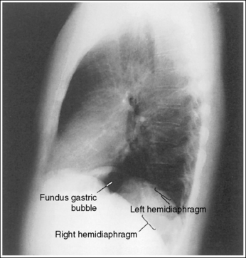
Image 14
No superimposition of humeral soft tissue over the anterior lung apices is present.
• Humeral positioning. Placing the humeri in an upright vertical position and instructing the patient to cross the forearms above the head prevent superimposition of the humeral soft tissue over the anterior lung apices (see Image 15). Many dedicated chest units provide holding bars for the patient's arms. When they are used, make sure that the humeri are placed high enough to prevent this soft tissue overlap. If the holding bars cannot be raised high enough and the patient is able to prevent motion, position the patient's arms as just described.
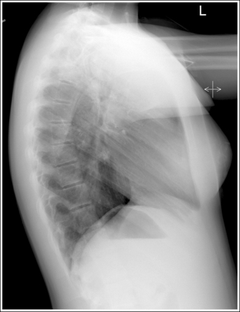
Image 15
The anteroinferior lung and the heart shadow are well defined.
• This area is most clearly defined when the patient is imaged in a standing position. If the patient is seated and leaning forward, the anterior abdominal tissue is compressed, obscuring the anteroinferior lung and the heart shadow; this is especially true in an obese patient (see Image 16). Consideration of patient condition dictates how the image will be taken. To best demonstrate this region on the seated patient, have the patient lean back slightly, allowing the anterior abdominal tissue to relax. Do not lean the patient so far back, however, that the posterior lungs are not on the image.
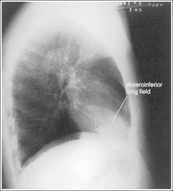
Image 16
The hemidiaphragms demonstrate a gentle, cephalically bowed contour, and the eleventh thoracic vertebra is entirely superimposed by the lung field, with the hemidiaphragms visible inferior to it, indicating full lung aeration.
• Maximum lung aeration. When a lateral chest projection demonstrates the hemidiaphragms with an exaggerated cephalic bow, in addition to a portion of the eleventh thoracic vertebra inferior to the hemidiaphragms in a patient with no condition to have caused such an image, full lung aeration has not been accomplished (see Image 17). Repeat the procedure with a deeper patient inspiration. The lungs must be fully inflated for lung markings to be evaluated. Chest images taken on expiration may also demonstrate a decrease in image density, because a decrease in air volume increases the concentration of pulmonary tissues.
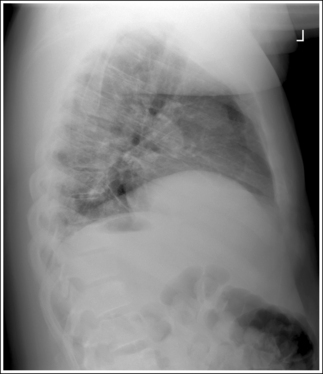
Image 17
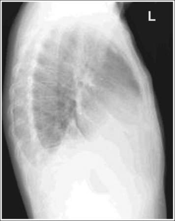
When the patient is in an upright position and fluid is present in the inferior lungs, the hemidiaphragms are not clearly identifiable (see Figure 3-5).
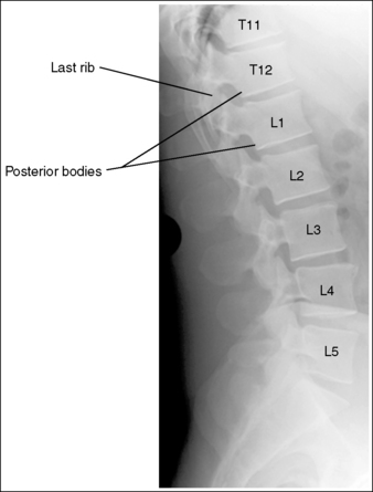
• Identifying the eleventh thoracic vertebra. The eleventh thoracic vertebra can be identified by locating the twelfth thoracic vertebra, which has the last rib attached to it, and counting up one. To confirm this finding, evaluate the curvature of the posterior aspect of the thoracic and lumbar bodies. The thoracic curvature is kyphotic (forward curvature) and the lumbar curvature is lordotic (backward curvature). Follow the posterior vertebral bodies of the lower thoracic and upper lumbar vertebrae, watching for the subtle change in curvature from kyphotic to lordotic. The twelfth thoracic vertebra is located just above this change (Figure 3-29). On most fully aerated adult lateral chest images, the diaphragms are demonstrated dividing the body of the twelfth thoracic vertebra.
Lateral Chest Image Analysis
Posterior ribs are directly superimposed, and approximately 0.5 inch (1.25 cm) of space is present between the right and left anterior ribs.
Correction
No correction movement is required. The superimposition is a result of the increased magnification of the right lung over the left lung as a result of the greater OID.
Analysis
The right and left posterior ribs are separated by more than 0.5 inch (1.25 cm), indicating that the chest was rotated. The gastric bubble has not been demonstrated, but the superior heart shadow is seen extending beyond the sternum and into the anteriorly situated lung, verifying that it is the left lung. The patient was positioned with the left thorax rotated anteriorly and the right thorax rotated posteriorly.
Correction
Position the right thorax slightly anteriorly. The amount of movement should be only half the distance between the posterior ribs. For this patient, the movement should be approximately 1 inch (2.5 cm).
Analysis
The right and left posterior ribs are separated by more than 0.5 inch (1.25 cm), indicating that the chest was rotated. The superior heart shadow does not extend beyond the sternum and the gastric air bubble is demonstrated adjacent to the posteriorly situated lung, verifying that the right lung is situated anterior to the sternum, and the left lung posteriorly. The patient was positioned with the right thorax rotated anteriorly and the left thorax rotated posteriorly.
Analysis
The right and left posterior ribs demonstrate differing degrees of separation. The patient has scoliosis. Evaluate the patient's accompanying PA projection to confirm this finding.
Correction
No correction movement is required. A lateral chest projection of a patient with scoliosis demonstrates uneven posterior rib separation.
Analysis
The left hemidiaphragm is superior to the right hemidiaphragm. This is verified by the visualization of the gastric bubble below the left hemidiaphragm. The patient's lower thorax was situated closer to the IR than the upper thorax (see Figure 3-27).
Correction
Before repeating the image, scrutinize the patient's accompanying PA projection carefully. Determine whether the hemidiaphragms are at the same height or whether a pathologic condition might have caused the left diaphragm to be projected above the right (see Figure 3-18). If no such condition is evident, repeat the procedure; shift the patient's hips away from the IR until the midsagittal plane is parallel with the IR.
Analysis
This is a lateral chest projection obtained with the patient in a right lateral projection. The right hemidiaphragm is situated superior to the left hemidiaphragm, and the heart shadow is enlarged.
Correction
If a right lateral projection is desired, no correction is needed. Otherwise, a lateral chest projection should be taken with the patient placed in a left lateral projection.
Correction
Have the patient raise the arms until the humeri are vertical, removing them from the field.
Analysis
The anterior abdominal tissue is pressing against the anteroinferior lung and heart shadows, preventing their clear visualization. The patient was leaning forward in a seated position.
Correction
Allow the patient to lean back slightly, relaxing the abdominal tissue. Do not lean the patient so far back, however, that the posterior lungs are not on the image.
CHEST: ANTEROPOSTERIOR PROJECTION (SUPINE OR WITH MOBILE X-RAY UNIT)
See Figure 3-30 and Box 3-4.
The date and time of examination, SID used, degree of patient elevation, and technical factors used are recorded on image.
• Patients in an intensive care unit (ICU) often have mobile chest images taken on a daily basis that are compared for subtle changes. Consistent positioning is important to ensure that the subtle changes are not caused by poor positioning, but is difficult to obtain when follow-up images are performed by multiple technologists. Consistency can best be accomplished through proper documentation. To do this, radiology departments use a sticker to record the information directly on the radiograph or, with digital radiography, the information is electronically annotated on the image. At a minimum, the information should include the date and time of examination, the SID used, the degree of patient elevation, and the technical factors used. The technologists should review this information prior to obtaining a subsequent chest image.
The heart demonstrates increased magnification when the images are compared with routine chest images.
• A 40- to 48-inch (102- to 120-cm) SID is used. This SID is lower than that used for routine chest images and demonstrates greater heart magnification because of the increase in x-ray divergence. The SID is often estimated during mobile procedures, but if available, a tape measure should be used to maintain appropriate SID, providing consistency in magnification and reducing the need to adjust technical factors.
The seventh thoracic vertebra is at the center of the exposure field. Both lungs, from the apices to costophrenic angles, are included within the collimated field.
• Centering the central ray to the midsagittal plane at a level approximately 4 inches (10 cm) inferior to the jugular notch places the seventh thoracic vertebra in the center of the image. This central ray placement also centers the lung field on the image. Center the IR to the central ray. Open the longitudinally collimated field to within 0.5 inch (2.5 cm) of the lateral skin line. For most adult AP chest projections, the full 14-inch (35-cm) length is needed. A 14- × 17-inch (35- × 43-cm) IR should be adequate to include all the required anatomic structures.
• IR size and direction for mobile chest image. The direction of IR placement (crosswise versus lengthwise) must also be considered to ensure full lung coverage. For the asthenic or hypersthenic patient, position the IR crosswise. For the sthenic patient, whose lung field is long and narrow, position the IR lengthwise. On inspiration, the lungs expand in three dimensions: transversely, anteroposteriorly, and vertically. Evaluate the transverse dimension to determine the direction in which the IR should be placed. View the lateral sides of the chest during the patient's deep inspiration to determine whether the lateral margins of the chest will remain within the IR boundaries. If the lateral chest margins move outside the IR boundaries during inspiration, consider placing the IR crosswise. It is safe to position the IR crosswise on most patients for portable chest imaging because the vertical dimension does not fully expand in a recumbent or seated patient.
The chest demonstrates an AP projection when the distances from the vertebral column to the sternal ends of the clavicles and lengths of the right and left corresponding posterior ribs are equal.
• The patient, IR, and central ray must be accurately aligned to avoid chest rotation. The mobile light field provides a means of centering the central ray to the patient, but it does not indicate off-angling. This must be visually estimated by the technologist to avoid distortion. To align the patient and IR, place the patient's shoulders and pelvis on a straight plane and position the IR parallel with the bed (Figure 3-31). On beds with special padding, it may be necessary to place sponges beneath different aspects of the IR to keep it level and parallel in both the transverse and longitudinal axes. Because the patient's chest and IR move simultaneously, if the IR is not level, the chest is rotated. To align the central ray with the patient and IR, adjust the central ray position until it is perpendicular to the midcoronal plane and IR. If the central ray is angled to the right or left side of the patient instead of being perpendicular, the anatomic structures farthest from the IR (manubrium and clavicles) will be projected in the direction toward which the central ray is angled. Once the procedure has been set up, the technologist needs to evaluate the x-ray tube and patient relationship from two perspectives—side to side angle as observed from behind the x-ray tube, and cephalic-caudal angulation as observed from the side of the patient and the x-ray beam. When doing so the technologist should stand as far away from the mobile unit as possible because misalignment is easier to see from a distance.
• Detecting chest rotation on a mobile image. You can detect poor IR balance or poor central ray alignment and, consequently, chest rotation by evaluating the distances between the vertebral column and the sternal ends of the clavicles and by comparing the lengths of the posterior ribs. When the right sternal clavicular end demonstrates less superimposition of the vertebral column and the right posterior ribs demonstrate greater length than the left, the patient's right side was placed closer to the bed (see Image 18). When the left sternal clavicular end is seen without superimposition of the vertebral column and the left side demonstrates greater posterior rib length than the right, the patient's left side was placed closer to the bed (see Image 19). If the cause of this rotation was poor central ray alignment with the patient and IR, the sternal clavicular end that is superimposed over the least amount of the vertebral column and the posterior ribs that demonstrate the greatest length represent the side of the chest toward which the central ray angle was directed. Off-angling the central ray toward the right side of the chest will result in the right sternal clavicular end being seen at a greater distance from the vertebral column and greater right side posterior rib length (see Image 18), whereas angling the central ray toward the left side of the chest will result in the left sternal clavicular end being seen at a greater distance from the vertebral column and greater left side posterior rib length (see Image 19). It will be necessary to evaluate the positioning setup on rotated AP chest projections carefully to determine whether rotation was caused by poor alignment of the patient and IR with the central ray.
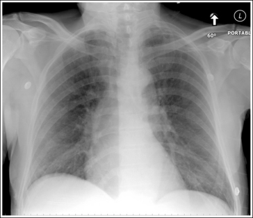
Image 18
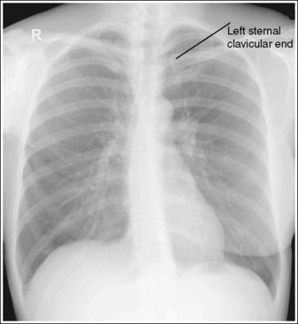
Image 19
The manubrium is superimposed over the fourth thoracic vertebra with approximately 1 inch (2.5 cm) of the apices demonstrated above the clavicles, and the posterior ribs demonstrate a gentle cephalically bowed contour.
• The alignment of the central ray with respect to the patient determines the relationship of the manubrium to the thoracic vertebrae, the amount of apical lung field seen above the clavicles, and the contour of the posterior ribs. For accurate alignment of this anatomy, position the central ray perpendicular to the patient's midcoronal plane. Inaccurate central ray angulation misaligns this anatomy and elongates or foreshortens the heart and lung structures. The anatomic structures positioned farthest from the IR will move the greatest distance when the central ray is angled; angling the central ray caudally for an AP chest projection projects the manubrium inferior to the fourth thoracic vertebra, demonstrating more than 1 inch (2.5 cm) of lung apices superior to the clavicles, and changes the posterior rib contour to vertical. A caudal angle also elongates the heart and lung structures (see Image 20). Angling the central ray cephalically projects the manubrium superior to the fourth thoracic vertebra, demonstrating less than 1 inch (2.5 cm) of lung apices superior to the clavicles, and changes the posterior rib contour to horizontal. A cephalic angle also foreshortens the heart and lung structures (see Image 21). The more the angulation is mispositioned, either caudally or cephalically, the more distorted the anatomy.
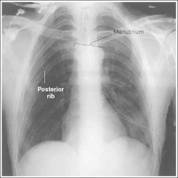
Image 20
Image 21
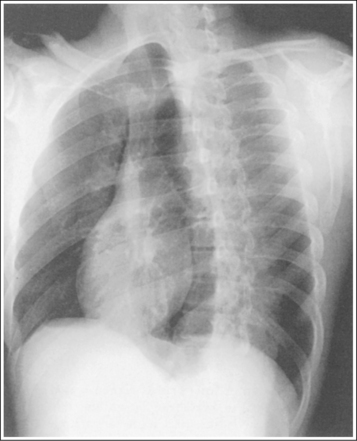
• Patient with spinal kyphosis. On the supine or mobile chest image of a patient with spinal kyphosis (excess posterior convexity of the thoracic vertebrae), the position of the manubrium and clavicles and the contour of the posterior ribs may appear similar to those on a chest image for which the central ray was angled caudally. Also, if the patient is unable to elevate the chin, it may be superimposed over the apical chest region (Figure 3-32); compensate for this patient condition by using a slight (5- to 10-degree) cephalic angulation.
• Supine patient. For the supine AP chest projection, the patient's kyphotic upper vertebral column is forced to straighten because of the gravitational pull on it. This straightening causes the manubrium and clavicles to move superiorly and results in the image demonstrating less than 1 inch (2.5 cm) of apical lung field superior to the clavicles. Placing a 5-degree caudal angle on the central ray can offset this.
The clavicles are positioned on the same horizontal plane.
• When the patient's condition allows, position the lateral ends of the clavicles on the same horizontal plane as the medial ends by depressing the patient's shoulders. Accurate positioning of the clavicles lowers the lateral ends of the clavicles, positioning the middle and lateral clavicles away from the apical chest region and improving visualization of the apical lung field. If the patient is unable to depress his or her shoulders, the middle and lateral ends of the clavicles will be seen in the apical chest region.
The scapulae are demonstrated within the lung field. The distal humeri have been abducted out of the imaging field.
• To position most of the scapulae outside the lung field, place the back of the patient's hands on the hips and rotate the elbows and shoulders anteriorly. Most patients who require mobile or supine chest images are incapable of positioning their arms in this manner, resulting in an image with the scapulae positioned in the lung field. In such a situation, abduct the patient's arms until they are placed outside the imaging field. Failure to do so will result in unnecessary exposure to the patient's arms (see Image 22).
Image 22
Nine or 10 posterior ribs are demonstrated above the diaphragm, indicating full lung aeration for the nonerect chest image.
• In a supine or seated patient the diaphragm is unable to shift to its lowest position because the abdominal organs are compressed and push against the diaphragm. As a result, the lungs are not fully aerated, and only 9 or 10 posterior ribs are demonstrated above the diaphragm. If fewer than nine posterior ribs are demonstrated, then full lung expansion has not been obtained (see Image 23).
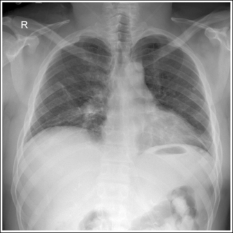
Image 23
Anteroposterior Chest Projection Analysis
The right sternal clavicular end is visualized away from the vertebral column, whereas the left sternal clavicular end is superimposed over the vertebral column and the right posterior ribs demonstrate greater length than the left. The IR was not positioned parallel with the bed but was positioned with the right side placed closer to the bed than the left, or the central ray was not aligned perpendicular to the IR but was off-angled toward the right side.
Correction
Place a sponge beneath the right IR border to position the IR parallel with the bed or slightly adjust the tube head and central ray toward the left side of the patient until it is aligned perpendicularly to the IR.
Analysis
The left sternal clavicular end is visualized away from the vertebral column, whereas the right sternal clavicular end is superimposed over the vertebral column, and the left posterior ribs demonstrate greater length than the right posterior ribs. The IR was not positioned parallel with the bed but was positioned with the left side placed closer to the bed than the right, or the central ray was not aligned perpendicularly to the IR but was off-angled toward the left side.
Correction
Place an elevating device beneath the left IR border to position the IR parallel with the bed or slightly adjust the tube head and central ray toward the right side of the patient until it is aligned perpendicularly to the IR.
Analysis
The manubrium is superimposed over the fifth thoracic vertebra, more than 1 inch (2.5 cm) of apical lung field is visible above the clavicles, and the lateral clavicular ends are elevated. The posterior ribs demonstrate a vertical contour. All are indications that a caudal angulation was used.
Correction
For this image to be improved, the central ray needs to be adjusted in a cephalad direction until it is aligned perpendicularly to the midcoronal plane.
Analysis
The manubrium is superimposed over the second thoracic vertebra, and less than 1 inch (2.5 cm) of apical lung field is visible above the clavicles. The posterior ribs demonstrate a horizontal contour. The central ray was angled cephalically.
Correction
For this image to be improved, the central ray needs to be adjusted caudally until it is aligned perpendicularly to the midcoronal plane.
Analysis
The patient's arms were not abducted away from the chest region, unnecessarily exposing them.
Correction
Abduct the patient's arms until they are placed outside the collimated field. Increase the transverse collimation to within 0.5 inch (1.25 cm) of the patient's skin line.
CHEST: ANTEROPOSTERIOR OR POSTEROANTERIOR PROJECTION (RIGHT OR LEFT LATERAL DECUBITUS POSITION)
See Figure 3-33 and Box 3-5.
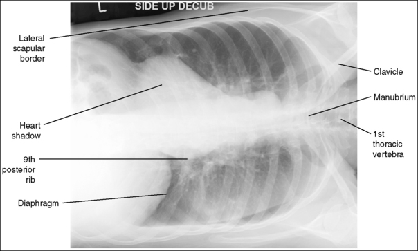
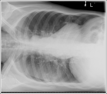
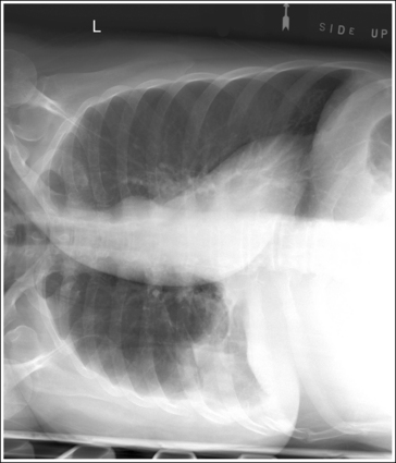
• Positioning to demonstrate pleural air or fluid. The AP or PA (lateral decubitus) projection is primarily used to confirm the presence of a pneumothorax or pleural effusion in the pleural cavity. To best demonstrate the presence of a pneumothorax, position the affected side of the thorax away from the tabletop or cart so that the air rises to the highest level in the pleural cavity. If the affected side were placed against the tabletop or cart, the air might be obscured by the mediastinal structures. To best demonstrate pleural effusion, position the affected side against the tabletop or cart. This positioning allows the fluid to gravitate to the lowest level of the pleural cavity, away from the mediastinal structures (Figure 3-34).
When imaging women with large pendulous breasts in the AP or PA (lateral decubitus) projection, it may be necessary to move and immobilize the overlapping breasts away from the areas where the air and fluid would collect (see Image 24). This will decrease the thickness of tissue in this region, providing more uniform density.
The seventh thoracic vertebra is at the center of the exposure field. Both lungs, from the apices to costophrenic angles, are included within the collimation field.
• Centering a perpendicular central ray to the midsagittal plane at a level approximately 7.5 inches (18 cm) inferior to the vertebra prominens for the PA projection and 4 inches (10 cm) inferior to the jugular notch for the AP projection places the seventh thoracic vertebra in the center of the image. This central ray placement also centers the lung field on the image. Center the IR to the central ray. Open the longitudinally collimated field to within 0.5 inch (2.5 cm) of the lateral skin line. For most adult AP chest projections, the full 14-inch (35-cm) length is needed. A 14- × 17-inch (35- × 43-cm) IR should be adequate to include all the required anatomic structures. For most patients, it is acceptable to use the dedicated chest unit, which will position the IR crosswise to the patient and still include the entire lung field on the image. In a recumbent patient, the diaphragm is unable to move to its lowest position on inspiration, preventing full vertical lung expansion. Because the lungs are unable to expand fully, a crosswise IR will provide adequate lung coverage. To be certain that the lateral borders are included on the image, center the IR and the central ray to the midsagittal plane.
The chest demonstrates an AP or PA projection. The distance from the lateral edges of the vertebral column to the sternal ends of the clavicles and the lengths of the right and left corresponding posterior ribs are equal.
• The decubitus chest image can be taken in an AP or a PA projection. In the AP projection, it is easier for the patient to maintain a true projection, without rotation, because the knees can be flexed. It is also easier for the patient to move closer to the IR and raise the arms when in an AP position. To avoid chest rotation, align the shoulders, the posterior ribs, and the posterior pelvic wings perpendicularly to the cart on which the patient is lying (Figure 3-35). This alignment positions the patient's shoulders and lungs at equal distances from the IR. Accomplish posterior rib and pelvic wing alignment by resting your extended flat hand against each, respectively, and then adjusting the patient's rotation until your hand is positioned perpendicularly to the cart. It is most common for a patient to lean the elevated shoulder, lung, and pelvic wing anteriorly when rotated. A pillow or other support placed between the patient's knees may help eliminate this forward rotation.
• Detecting chest rotation. Rotation is readily detected on an AP or PA (lateral decubitus) chest projection by evaluating the distances between the vertebral column and the sternal ends of the clavicles and by comparing the lengths of the posterior ribs. On a nonrotated decubitus chest image, the distances and lengths, respectively, on each side of the patient should be equal. On a rotated AP projection, the sternal clavicular end that is superimposed over the lesser amount of the vertebral column, and the side on which the posterior ribs demonstrate the greatest length, is the side of the chest positioned closer to the IR (see Images 25 and 26). The opposite is true for a PA projection. For this projection, the sternal clavicular end that is superimposed over the least amount of the vertebral column and the posterior ribs that demonstrate the greatest length represent the side of the chest positioned farther from the IR.
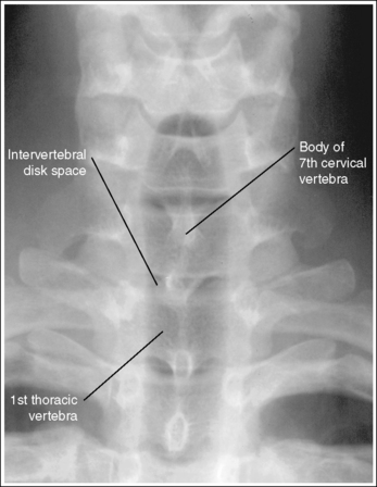
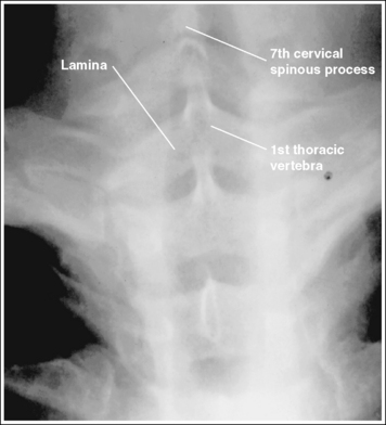
• AP versus PA chest images: Determine whether a chest image was taken in an AP or PA projection by analyzing the appearance of the sixth and seventh cervical vertebrae and the first thoracic vertebra. In the AP projection, these vertebral bodies and their intervertebral disk spaces are demonstrated without distortion (Figure 3-36). In the PA projection, the vertebral bodies are distorted, the intervertebral disk spaces are closed, and the spinous processes and laminae of these three vertebrae are well demonstrated (Figure 3-37). The reason for these variations is related to the divergence of the x-ray beam used to image these three vertebrae and the anterior convexity of the cervical and upper thoracic vertebrae.
The arms, mandible, and lateral borders of the scapulae are situated outside the lung field, and the lateral aspects of the clavicles are projected upward.
• The lateral borders of the scapulae are drawn away from the lung field when the patient's arms are positioned above the head. This positioning also draws the lateral ends of the clavicles superiorly. If the arms are not positioned in this manner, the arms and the lateral borders of the scapulae are demonstrated within the upper lung field (see Image 25).
• To prevent the chin from being superimposed over the lung apices on the image, position the patient with the chin elevated.
The manubrium and the fourth thoracic vertebra are superimposed, and the lungs and heart are demonstrated without foreshortening.
• The tilt of the midcoronal plane determines the degree of lung and heart foreshortening and the transverse level at which the manubrium is situated in comparison to the fourth thoracic vertebra. When the midcoronal plane is positioned parallel with the IR, the lungs and heart are demonstrated without foreshortening and the manubrium and fourth thoracic vertebra are superimposed over each other. If the image is taken in an AP projection and the superior midcoronal plane is tilted anteriorly (forward), the manubrium will move inferior to the fourth thoracic vertebra (see Image 27). Conversely, if the superior midcoronal plane is tilted posteriorly (backward), the manubrium will move superior to the fourth thoracic vertebra (see Image 28). If the image is taken in a PA projection and the superior midcoronal plane is tilted anteriorly, the manubrium will move inferior to the fourth thoracic vertebra. Conversely, if the superior midcoronal plane is tilted posteriorly, the manubrium will move superior to the fourth thoracic vertebra.
Nine or 10 posterior ribs are demonstrated above the diaphragm.
• In a recumbent position, the diaphragm is unable to shift to its lowest position because of pressure from the peritoneal cavity. As a result, the lungs are not fully aerated, and only 9 or 10 posterior ribs are demonstrated above the diaphragm.
The lung field positioned against the cart is demonstrated without superimposition of the cart pad.
• Elevating the patient on a radiolucent sponge or on a hard surface, such as a cardiac board, prevents the chest from sinking into the cart pad. When the patient's body is allowed to sink into the cart pad, artifact lines are seen superimposed over the lateral lung field of the side placed against the cart. Because fluid in the pleural cavity gravitates to the lowest level, it is in this area that the fluid will be demonstrated, and superimposition of the cart pad and the lower lung field may obscure fluid that has settled in the lowest level.
Anteroposterior and Posteroanterior (Lateral Decubitus) Chest Projection Analysis
Correction
When imaging women with large pendulous breasts in the AP or PA (lateral decubitus) projection, it may be necessary to move and immobilize the overlapping breasts away from the areas where the air and fluid collect. This will decrease the thickness of tissue in this region, providing more uniform density.
Analysis
The right sternal clavicular end is superimposed over the vertebral column, the posterior ribs on the left side demonstrate the greater length, and the arms are superimposed over the right lung apex. The patient's left side was rotated toward the IR, and the arm was positioned at a 90-degree angle to the body.
Correction
Rotate the patient's left side away from the IR until the patient's shoulders, posterior ribs, and posterior pelvic wing are aligned perpendicularly to the cart. Elevate the patient's right arm until it is positioned above the lung field.
Analysis
The left sternal clavicular end is superimposed over the vertebral column, and the posterior ribs on the right side demonstrate the greater length. The patient's right side was rotated toward the IR.
Correction
Rotate the patient's right side away from the IR until the patient's shoulders, posterior ribs, and posterior pelvic wing are aligned perpendicularly to the cart.
Analysis
The manubrium is superimposed over the fifth thoracic vertebra, indicating that the superior midcoronal plane was tilted anteriorly.
Correction
Move the superior midcoronal plane posteriorly until the midcoronal plane is parallel with the IR.
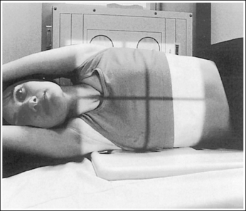
CHEST: ANTEROPOSTERIOR AXIAL PROJECTION (LORDOTIC POSITION)
See Figure 3-38.
Overlying soft tissues, clavicles, and upper ribs often obscure the apical lung markings on a PA projection of the chest. The anterior ends of the first ribs may also project a suspicious looking shadow in the apices. The AP axial projection is taken to demonstrate areas of the apical lungs obscured on the PA projection and to provide a different anatomic perspective that can be used to evaluate suspicious areas (Box 3-6).
The superior lung field is at the center of the exposure field. The clavicles, apices, and two thirds of the lung field are included within the collimated field.
• Centering the central ray to the midsagittal plane halfway between the manubrium and the xiphoid positions the superior lung field at the center of the image. Because the lung fields are foreshortened, this centering will include most of the lung fields on the image. A higher centering is required if only the lung apices are desired. Lung foreshortening also creates the need for tight vertical collimation to prevent unnecessary exposure of abdominal and cervical vertebral tissue. Center the IR to the central ray.
• A 14- × 17-inch (35- × 43-cm), lengthwise IR should be adequate to include all the required anatomic structures. Longitudinally collimate to within 0.5 inch (1.25 cm) of shoulders and transversely collimate to 0.5 inch (1.25 cm) of lateral skin line.
The sternal ends of the clavicles are projected superiorly to the lung apices at the level of the first thoracic vertebra. The heart shadow can be outlined, although it is foreshortened and wider than on a corresponding PA chest projection. The posterior and anterior portions of the first through fourth ribs lie horizontally and are almost superimposed.
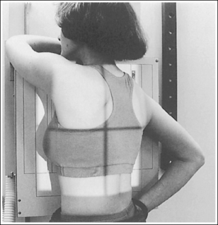
• The clavicles are projected above the apices, and the upper ribs are superimposed by positioning the patient using one of three methods. First, the patient's back can be arched, leaning the upper thorax and shoulders toward the IR, as demonstrated in Figure 3-39. The correct amount of arching is accomplished when the patient's feet are placed approximately 12 inches (30 cm) away from the IR before the back is arched. The angle formed between the midcoronal body plane and IR should be approximately 45 degrees. Second, the patient remains completely upright, and a 45-degree cephalic central ray angulation is used to shift the clavicles (Figure 3-40). Third, the patient's back is arched as much a possible and the central ray is angled cephalically the amount necessary to equal a 45-degree angle. For example, if the patient is able to arch until the midcoronal plane is placed at a 30-degree angle to the IR, the needed central ray angle would be 15 degrees. With each of these methods, the clavicles are projected above the apices onto the first thoracic vertebra, and the anterior ribs are projected onto their corresponding posterior ribs.
• Poor patient or central ray positioning. Inadequate back extension or central ray angulation is identified on an image when the clavicles are not projected superiorly to the lung apices and when the anterior and posterior ribs are not superimposed. When the patient's back is not arched enough or when more cephalic angulation is needed, the clavicles superimpose the lung apices, and the anterior ribs are demonstrated inferior to their corresponding posterior rib (see Image 29). If an image is obtained in which lung fields have been so foreshortened that the apices are obscured and the posterior ribs are superimposed and cannot be distinguished, the patient's back was arched too much or the cephalic angle was too extreme (see Image 30).
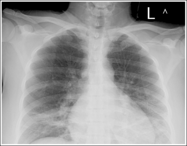
Image 29
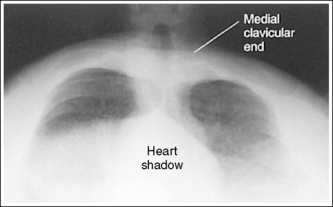
Image 30
The lateral borders of the scapulae are drawn away from the lung field, and the superior angles of the scapulae are demonstrated away from lung apices.
• The lateral borders and the superior angles of the scapulae are drawn away from the lung fields by placing the back of the patient's hands on the hips and rotating the elbows and shoulders anteriorly. This position allows visualization of the lung apices without scapular obstruction. When the elbows and shoulders are not rotated anteriorly, the lateral borders of the scapulae are demonstrated in the lung fields, and the superior scapular angles are projected into the lung apices (see Image 31).
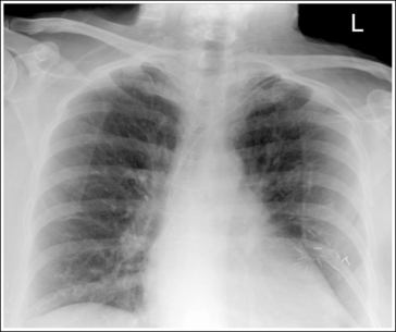
Image 31
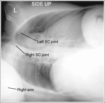
The chest demonstrates no signs of rotation when the distances from the vertebral column to the sternal ends of the clavicles are equal.
• The patient's shoulders should be equal distances from the IR to prevent rotation. Chest rotation can be identified on an AP axial projection by evaluating the distance between the vertebral column and the sternal ends of the clavicles or the sternoclavicular (SC) joints. When the distances between the sternal clavicles and the vertebral column are unequal, the SC joint that is superimposed over the smaller amount of the vertebral column is the side of the chest that was positioned closer to the IR.
Anteroposterior Axial Chest Projection Analysis
The clavicles are superimposed over the lung apices, and the anterior ribs are demonstrated inferior to their corresponding posterior rib. Either the patient's back was not arched enough or the central ray was not angled cephalically enough to obtain a 45-degree angle between the midcoronal plane and central ray.
Correction
If the patient's back was arched to obtain this image, increase the amount of arch or add a cephalic angulation until the midcoronal plane and central ray form a 45-degree angle.
Analysis
The lung fields demonstrate excessive foreshortening, and the individual ribs cannot be identified. Either the patient's back was arched too much or the central ray was angled too cephalically.
Correction
If the patient's back was arched to obtain this image, decrease the amount of arch. If this examination was obtained by using a cephalic angulation, decrease the degree of central ray angulation until the midcoronal plane and central ray form a 45-degree angle.
CHEST: POSTEROANTERIOR OBLIQUE PROJECTION (RIGHT ANTERIOR OBLIQUE AND LEFT ANTERIOR OBLIQUE POSITIONS)
See Figure 3-41 and Box 3-7.
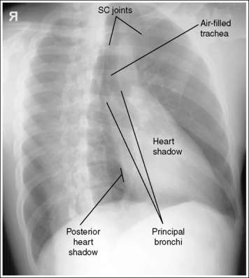
The right and left principal bronchi are at the center of the exposure field. The apices, costophrenic angles, and lateral chest walls are included within the collimated field.
• Centering a perpendicular central ray at a level approximately 7.5 inches (18 cm) inferior to the vertebra prominens places the central ray at the level of the bronchi. Accurate transverse positioning is obtained when the same amount of IR distance is present on both sides of the patient. A 14- × 17-inch (35- × 43-cm) IR should be adequate to include all the required anatomic structures. Center the IR to the central ray. Open the transversely collimated field to within 0.5 inch (2.5 cm) of the lateral skin line. For most adult AP chest projections, the full 17-inch (43-cm) length is needed, although you should collimate on smaller patients.
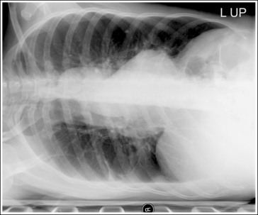
Approximately twice as much lung field is demonstrated on one side of the thoracic vertebrae as on the other side, and the SC joints are demonstrated without spinal superimposition, indicating that a 45-degree obliquity has been obtained.
• Rotating the patient until the midcoronal plane is aligned 45 degrees to the IR (Figure 3-42) provides the reviewer with an additional perspective of the lungs, which will assist in the detection of pulmonary diseases or artifacts. The lung field better demonstrated on an AP projection is the one positioned farther from the IR. An RAO position demonstrates the left lung, whereas an LAO position demonstrates the right lung.
• Verifying accuracy of obliquity. When evaluating an image, you can be certain that a 45-degree obliquity has been obtained if (1) twice as much lung field is demonstrated on one side of the thoracic vertebrae as on the other side, and (2) the sternoclavicular (SC) joints, air-filled trachea, and principal bronchi are demonstrated without spinal superimposition. The heart shadow is also demonstrated without spinal superimposition on an RAO chest image, whereas a portion of the heart shadow is superimposed over the thoracic vertebrae on an LAO chest image. Because the heart is located more to the left of the thoracic vertebrae, a 60-degree patient obliquity is necessary to demonstrate the heart shadow without spinal superimposition on the LAO. Figure 3-43 demonstrates a 45-degree LAO chest image. Note that the lung field on one side is twice as large as on the other and that slight superimposition of the thoracic vertebrae and heart shadow is present. Compare this image with the 60-degree LAO chest image shown in Figure 3-44. Note that more than twice as much lung field is present on one side of the thoracic vertebrae as on the other in Figure 3-44, and that the heart shadow and thoracic vertebrae are not superimposed. How much obliquity should be obtained depends on the examination indications. When the examination is being performed to evaluate the lung field, a 45-degree oblique image is required; when the outline of the heart is of interest, a 60-degree oblique image is required.
• Repositioning for improper patient rotation. If the desired 45-degree obliquity is not obtained on a PA oblique chest projection, compare the amount of lung field demonstrated on both sides of the thoracic vertebrae. If the image demonstrates more than twice the lung field on one side of the thoracic vertebrae as on the other side, the patient was rotated more than 45 degrees. If less than twice the lung field is demonstrated on one side of the thoracic vertebrae as on the opposite side, the patient was not rotated enough (see Image 32). To determine repositioning movements for the 60-degree LAO image, evaluate the heart shadow and thoracic vertebrae superimposition. With adequate obliquity, the heart shadow is positioned just to the right of the thoracic vertebrae. If the PA oblique projection is less than 60 degrees, the heart shadow is superimposed over the thoracic vertebrae, as on a 45-degree LAO chest image. Excess obliquity produces an image similar to a rotated lateral chest projection.
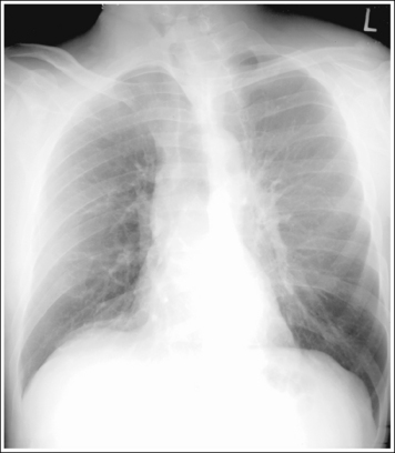
Image 32
• AP oblique chest projections. Routinely, PA oblique projections are performed for oblique chest images because they position the heart closer to the IR. When AP oblique projections are taken, however, the preceding evaluation corresponds in the following way. The LPO position demonstrates the lung situated closer to the IR, which is the left lung. To review this position, use the RAO evaluation previously described. For the RPO position, the right lung is of interest and the LAO evaluation should be followed. A 45-degree obliquity is required in the LPO image to rotate the heart away from the thoracic vertebrae, but a 60-degree obliquity is needed for the RPO position.
The manubrium is situated at the same level as the fourth thoracic vertebra, with approximately 1 inch (2.5 cm) of the apical lung field visible above the clavicles, and the lungs and heart are demonstrated without foreshortening.
• The tilt of the midcoronal plane determines the relationship of the manubrium to the thoracic vertebrae, the amount of apical lung field seen superior to the clavicles, and the degree of lung and heart foreshortening. When the midcoronal plane is vertical, the manubrium is projected at the level of the fourth thoracic vertebra, approximately 1 inch (2.5 cm) of the apices are visible above the clavicles, and the lungs and heart are demonstrated without foreshortening. In a PA oblique projection, if the superior midcoronal plane is tilted anteriorly (forward), as demonstrated in Figure 3-21, the lungs and heart are foreshortened, the manubrium is situated at a transverse level inferior to the fourth thoracic vertebra or lower, and more than 1 inch (2.5 cm) of apices is demonstrated above the clavicles (see Image 6). Conversely, if the superior midcoronal plane is tilted posteriorly (backward), as demonstrated in Figure 3-22, the lungs and heart are foreshortened, the manubrium is situated at a transverse level above the fourth thoracic vertebrae, and less than 1 inch (2.5 cm) of apices is demonstrated superior to the clavicles (see Image 7). The opposite is true for an AP oblique projection. Anterior tilt of the superior midcoronal plane will result in the manubrium projecting inferior to the fourth thoracic vertebra, and posterior tilt of the superior midcoronal plane will result in the manubrium projecting superior to the fourth thoracic vertebra.
Ten or 11 posterior ribs are demonstrated above the hemidiaphragms, indicating full lung aeration.
• If fewer than 10 posterior ribs are demonstrated, the lungs were not fully inflated. Determine whether a patient condition hindered full aeration. If not, repeat the image after full inspiration.
Posteroanterior Oblique Chest Projection Analysis
This image was taken with the patient in an LAO position. Less than twice the lung field is demonstrated on the left side of the thoracic vertebrae as on the right side. The thoracic vertebrae are superimposed over a portion of the heart shadow and the air-filled trachea. The obliquity was less than 45 degrees.
PEDIATRIC CHEST
The lungs of the neonate continue to grow for at least 8 years after birth. The growth results mainly from an increase in the number of respiratory bronchioles and alveoli. Only from one eighth to one sixth of the number of alveoli in adults are present in newborn infants, causing the lungs to be denser. Therefore on neonate and infant chest images, the lungs demonstrate less image contrast within them and between them and the surrounding soft tissue than on adult chest images.
NEONATE AND INFANT CHEST: ANTEROPOSTERIOR PROJECTION
See Figure 3-45 and Box 3-8.
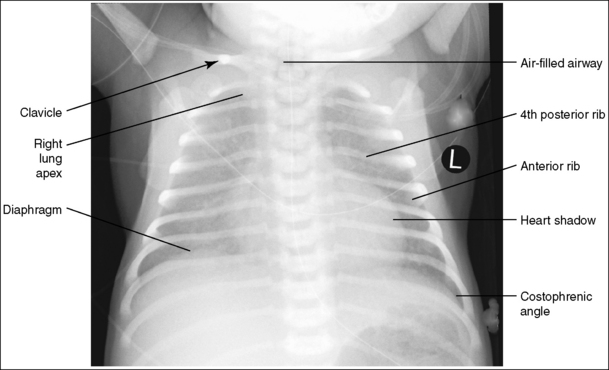
The fourth thoracic vertebra is at the center of the exposure field. The upper airway, lungs, mediastinal structures, and costophrenic angles are included within the collimated field.
• Center the neonate or infant's chest to the center of an 8- × 10-inch (18- × 24-cm), lengthwise IR, and center a perpendicular central ray to the midsagittal plane at the level of the mammary line (imaginary line connecting the nipples) for neonates and small infants. A larger IR and slightly inferior centering may be needed for larger infants. This IR and central ray placement centers the lung field on the image, permitting tight collimation on all sides of the lungs. Open the longitudinal collimation to include the upper airway (infant's bottom lip) and costophrenic angles (tenth posterior rib) and transversely collimate to within 0.5 inch (1.25 cm) of the lateral skin line.
• As the lungs grow, the shape of the thoracic cavity changes from the neonate and infant's short, wide shape to the older child and adult's longer, narrower shape. The technologist must adjust the central ray centering point to accommodate the changing shape to avoid distortion and clipping lung structures when tightly collimating.
The chest demonstrates an AP projection. The distances from the vertebral column to the sternal ends of the clavicles are equal, and the lengths of the right and left corresponding posterior ribs are equal.
• Rotation on a supine or mobile chest image is caused by poor patient positioning or central ray alignment. To position the infant without rotation accurately, immobilize the child using the immobilization equipment (Figure 3-46) or have an attendant use two hands for restraint (Figure 3-47). The thumb, forefinger, and middle finger of one hand are used to clasp the infant's wrists above his or her head, and the same digits of the other hand clasp the infant's ankles. The head and toes are positioned straight up. Head rotation is the most common cause of chest rotation in neonates and infants. The chest will rotate in the same direction in which the infant's head is rotated. Align the central ray perpendicularly to the midsagittal plane and IR. To avoid rotation caused by poor central ray alignment, make certain that the central ray is not off-angled toward the right or left lateral side of the infant instead of being perpendicular. If the central ray is off-angled toward the lateral side of the infant, the anatomic structures farthest from the IR (clavicles and anterior ribs) will be projected in the direction toward which the central ray is off-angled.
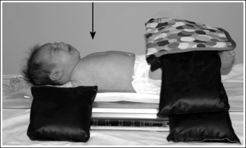
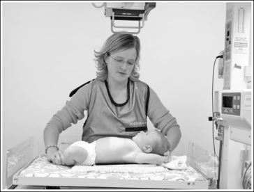
Figure 3-47 Proper patient positioning for infant AP chest projection using immobilization equipment.
• Detecting chest rotation. Chest rotation is detected by evaluating the distance between the vertebral column and the sternal ends of the clavicles and by comparing the length of the right and left inferior posterior ribs. The sternal clavicular end that is demonstrated farther from the vertebral column and the side of the chest that demonstrates the longer posterior ribs represents the side of the chest toward which the infant is rotated (see Images 33, 34, and 35). If the cause of the rotation is poor central ray alignment, the sternal clavicular end demonstrated farther from the vertebral column and the side of the chest with the longer posterior ribs represents the side of the chest toward which the central ray off-angled.
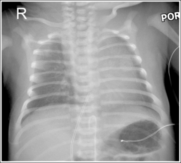
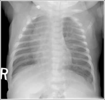
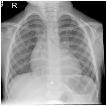
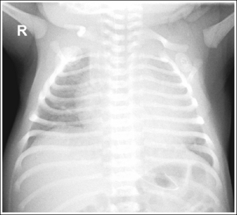
The anterior ribs are projecting downward and the posterior ribs demonstrate a gentle, cephalically bowed contour.
• The neonate or infant supine AP chest projection tends to have a lordotic appearance because of the lack of kyphotic thoracic curvature that is seen in adults. Some facilities offset this appearance by angling the central ray 5 degrees caudally or by tilting the foot end of the bed 5 degrees lower than the head end. Proper central ray centering will also help to reduce this lordotic appearance. Because the chest in neonates and infants is shorter than in adults, a common error is to center the central ray too inferiorly, resulting in an increase in the lordotic appearance.
A neonate or infant chest projection that demonstrates an excessively lordotic appearance will demonstrate cephalically projected anterior ribs and posterior ribs without the gentle, cephalically bowed contour (see Image 36). Such distortion foreshortens the lungs and mediastinal structures, causing the cardiac apex to appear uptilted and the main pulmonary artery to be concealed beneath the cardiac silhouette.
Neonate: Eight posterior ribs are demonstrated above the diaphragm, and the lungs demonstrate a fluffy appearance with linear-appearing connecting tissue, indicating full lung aeration for the neonatal chest image.
Infant: Nine posterior ribs are demonstrated above the diaphragm.
• The appearance of the neonate's lungs may change with even one rib's difference in inflation. With dense substances such as blood, pus, protein, and cells filling the alveoli, it is the addition of the less dense air that will give the image the fluffy appearance, because the air is demonstrated on the image as a darker density among the lighter densities of blood, pus, protein, and cells. A lung that demonstrates a white-out appearance, even though the diaphragm is below the eighth rib, is filled with dense substances that do not allow air to fill the alveoli.
For neonates and infants breathing without a respirator, observe the chest movement and expose the image after the infant takes a deep breath. Chest images that are taken on expiration may demonstrate a decrease in image density because a decrease in air volume increases the concentration of pulmonary tissues (see Images 37 and 38).
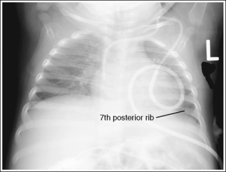
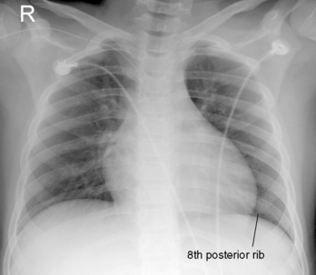
The chin does not obscure the airway or apical lung field.
• To prevent the chin from being superimposed on the airway and apical lung field, lift the neonate or infant's chin until the neck is in a neutral position. When the chin is superimposed on the airway and apical lung field, ETT placement cannot be evaluated (see Image 39).
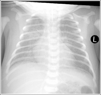
Neonate and Infant Anteroposterior Chest Projection Analysis
The left sternal clavicular end is demonstrated farther from the vertebral column than the right sternal clavicular end, and the left lower posterior ribs are longer than the right.
Correction
Rotate the thorax toward the right side until the midcoronal plane is parallel with the IR and perpendicular to the central ray. Make certain that the patient's face is facing forward.
Analysis
The right sternal clavicular end is demonstrated farther from the vertebral column than the left sternal clavicular end, and the right lower posterior ribs are longer than the left.
Correction
Rotate the thorax toward the left side until the midcoronal plane is parallel with the IR and perpendicular to the central ray.
Analysis
The chest demonstrates an excessively lordotic appearance. The anterior ribs are projecting upwardly, and the posterior ribs do not demonstrate the slight upwardly bowed appearance, but are horizontal. The central ray was centered inferior to T4.
Correction
Move the central ray superiorly to align it better with the upper thorax. A 5-degree caudal angle may also be added to help align the central ray and thorax better.
Analysis
Six posterior ribs are demonstrated above the diaphragm. Neonates should have at least eight and infants at least nine posterior ribs visible above the diaphragm. The lungs were not fully aerated.
Correction
If possible, take the exposure after the patient takes a deeper inspiration. If the patient is on a conventional ventilator, expose the image when the manometer is at its highest level, indicating a deep inspiration.
Analysis
Eight posterior ribs are demonstrated above the diaphragm. Infants should have at least nine posterior ribs visible above the diaphragm. The lungs were not fully aerated.
CHILD CHEST: POSTEROANTERIOR AND ANTEROPOSTERIOR PROJECTIONS
See Figures 3-48 and 49.
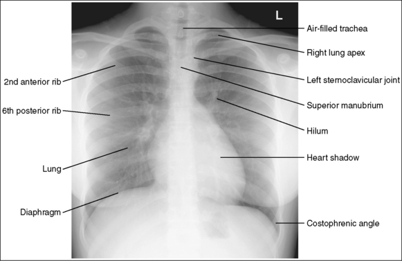
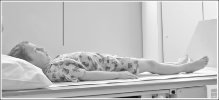
The analysis of the child PA and AP chest projections is the same as that for the infant or adult PA or AP chest, already discussed. The size of the child determines which criterion best meets the situation. For a discussion on topics needed to analyze Images 40 through 44 that follow, refer to the PA-AP adult or infant chest discussions earlier in this chapter.
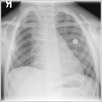
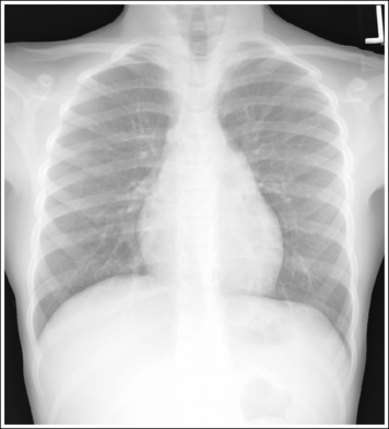
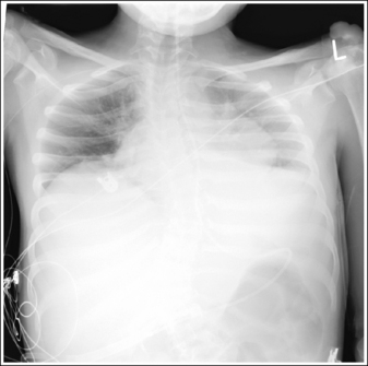
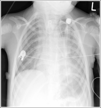
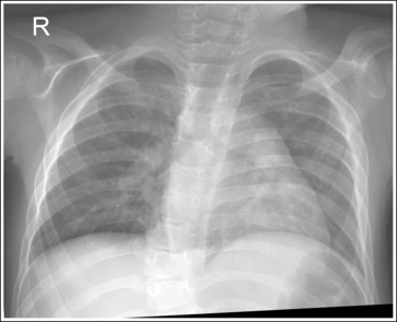
Child Chest Posteroanterior and Anteroposterior Chest Projection Analysis
The right sternal clavicular end is visible without superimposing the vertebral column, and the left sternal clavicular end superimposes the vertebral column. The patient was rotated toward the left side.
Correction
Rotate the right side of the patient's thorax toward the IR until the shoulders are at equal distances from the IR.
Analysis
The manubrium is at the level of the second thoracic vertebra, and less than 0.5 inch (1.25 cm) of apical lung field is demonstrated superior to the clavicles. The patient's upper midcoronal plane was tilted posteriorly.
Analysis
Only six posterior ribs are demonstrated above the diaphragm. The manubrium is superimposed over the second thoracic vertebra, the posterior ribs demonstrate a horizontal contour, and less than 1 inch (2.5 cm) of apical lung field is visible above the clavicles. The image was taken on expiration, and the central ray was angled too cephalically.
Correction
If the patient's condition allows, take the exposure after coaxing the patient into a deeper inspiration and adjust the central ray caudally until it is aligned perpendicularly to the patient's midcoronal plane.
Analysis
The manubrium is superimposed over the fifth thoracic vertebra, the posterior ribs demonstrate a vertical contour, and more than 1 inch (2.5 cm) of apical lung field is visible above the clavicles. The central ray was angled too caudally.
Correction
Adjust the central ray cephalically until it is aligned perpendicular to the patient's midcoronal plane.
NEONATE AND INFANT CHEST: CROSS-TABLE LATERAL PROJECTION (LEFT LATERAL POSITION)
See Figure 3-50 and Box 3-9.
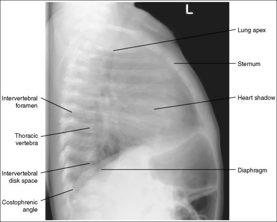
The midcoronal plane, at the level of the fifth thoracic vertebra, is at the center of the exposure field. The entire lung field, including the apices and costophrenic angles, and the posterior ribs and airway are included within the collimated field.
• Lateral chest projections are useful for assessing the degree of inflation, permit confident recognition of cardiomegaly, and provide the clearest view of the thoracic vertebrae and sternum. The needed anatomic structures are placed on a lateral chest projection when the neonate or infant is supine, and an 8- × 10-inch (18- × 24-cm), lengthwise IR is positioned against the neonate or infant's left lateral surface. The chest is placed in the middle of the IR by elevating the patient on a radiolucent sponge, and a horizontal central ray is positioned to the midcoronal plane at a level just inferior to the mammary line. To position the infant without rotation accurately, immobilize the child using immobilization equipment (Figure 3-51) or have an attendant use two hands for restraint (Figure 3-52). A larger IR and slightly inferior centering may be needed for larger infants. This IR and central ray placement centers the lung field on the image, permitting tight collimation on all sides of the lungs. Open the longitudinal collimation to include the midcervical vertebrae and costophrenic angles, and transversely collimate to within 0.5 inch (1.25 cm) of the lateral skin line.
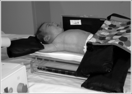
Figure 3-51 Proper patient positioning for an infant cross-table lateral chest projection using immobilization equipment.
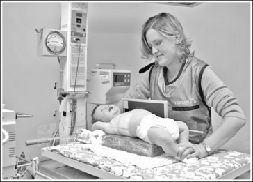
• Cross-table versus overhead lateral projections. Neonates are very sensitive. Performing a cross-table lateral projection on the neonate instead of the overhead lateral will reduce the amount of disturbance. Also, on overhead lateral projections, the lung adjacent to the IR tends to collapse, whereas the superior lung tends to overinflate.
The chest demonstrates no rotation when the posterior ribs are superimposed and the sternum is in profile.
• To avoid chest rotation, align an imaginary line connecting the shoulders, the posterior ribs, and the posterior pelvic wings perpendicular to the IR. Because the OID difference between the right and left lung fields is minimal on neonates and small infants, the posterior ribs on lateral chest projections do not demonstrate the 0.5-inch (1.25-cm) separation that is seen on adult lateral chest projections, but instead are directly superimposed.
• Detecting chest rotation. Chest rotation is effectively detected on a lateral chest projection by evaluating the degree of superimposition of the posterior ribs. When the posterior ribs are demonstrated without superimposition, the chest was rotated for the image (see Images 45 and 46). One means of identifying the lung that is positioned posteriorly is to locate the most inferiorly demonstrated right and left corresponding ribs. The rib on the right side will be projected slightly more inferiorly than the rib on the left side because it is positioned farthest from the IR. The heart shadow and gastric bubble may also be used, as described in the earlier discussion of the adult lateral chest projection.
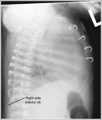
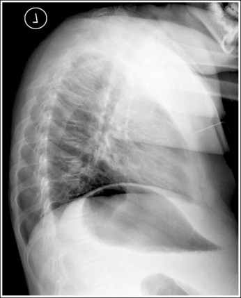
Humeral soft tissue is not superimposed over the anterior lung apices.
• Positioning the humeri upward, near the patient's head, prevents superimposition of the humeral soft tissue over the anterior lung apices (see Image 46).
The chin is not in the exposure field.
• Good radiation protection practices dictate that anatomic structures that are not evaluated on an image should not be included, whenever possible. To prevent the chin from being included in the exposure field, lift it upward above the collimation field (see Image 47).
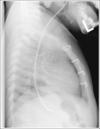
Image 47
The hemidiaphragms form a gentle cephalic curve.
• Respiration. For neonates and infants breathing without a respirator, observe the chest movement and take the exposure after the infant takes a deep breath. Chest images that are taken on expiration may demonstrate a decrease in image density, because a decrease in air volume increases the concentration of pulmonary tissues. With underaeration, the cephalic curve of the hemidiaphragms is exaggerated and their position is higher in the thorax (see Image 48).
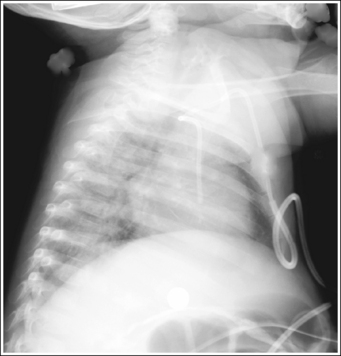
Image 48
Neonate and Infant Lateral Chest Projection Analysis
The posterior ribs are demonstrated without superimposition. The right lung is posterior to the left lung, as identified by the more inferior projection of the posterior rib on the right side compared with the left.
Correction
Rotate the right side of the thorax away from the bed or cart until the shoulders and posterior ribs are aligned perpendicular to the IR.
Analysis
The humeral soft tissue is superimposed over the anterior lung apices. The patient's arms were not elevated. The left lung is anterior to the right lung, as identified by the gastric air bubble seen beneath the left hemidiaphragm.
Correction
Raise the patient's arms until the humeri are next to the patient's head. Rotate the left side of the thorax posteriorly until the shoulders and posterior ribs are aligned perpendicularly to the IR.
CHILD CHEST: LATERAL PROJECTION (LEFT LATERAL POSITION)
See Figures 3-53 and 3-54.
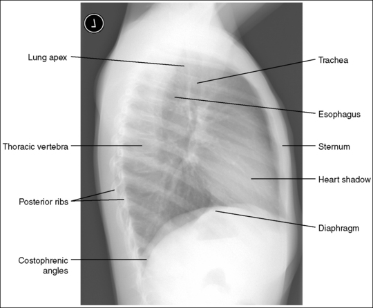
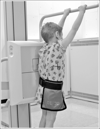
The analysis of the child lateral chest projection is the same as that of the infant or adult lateral chest projection (see earlier). The size of the child determines which criterion best meets the situation. For a discussion on the topics needed to analyze Images 49 through 51 that follow, see the lateral adult or infant chest discussions earlier in this chapter.
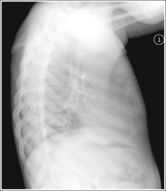
Image 49
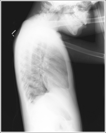
Image 50
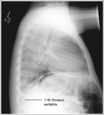
Image 51
Child Lateral Chest Projection Analysis
More than 0.5 inch (1.25 cm) of separation is demonstrated between the posterior ribs. The gastric air bubble is adjacent to the anteriorly located lung, indicating that the left lung is anteriorly positioned. The chin is within the collimated field, and the humeral soft tissue is superimposed over the superior lung field. The chin and the humeri were not elevated.
Correction
Rotate the right side of the thorax anteriorly and the left side posteriorly until the shoulders and the posterior ribs are aligned perpendicularly to the IR. Elevate the chin outside the collimated field, and raise the humeri next to the patient's head.
Analysis
Anatomic artifacts (patient's arms and mandible) are demonstrated on this image. Poor radiation protection practices are demonstrated.
Correction
Raise the patient's chin to bring it above the level of the chest and out of a properly collimated field. Increase the transverse collimation to within 0.5 inch (1.25 cm) of thorax skin line.
NEONATE AND INFANT CHEST: ANTEROPOSTERIOR PROJECTION (RIGHT OR LEFT LATERAL DECUBITUS POSITION)
See Figure 3-55 and Box 3-10.
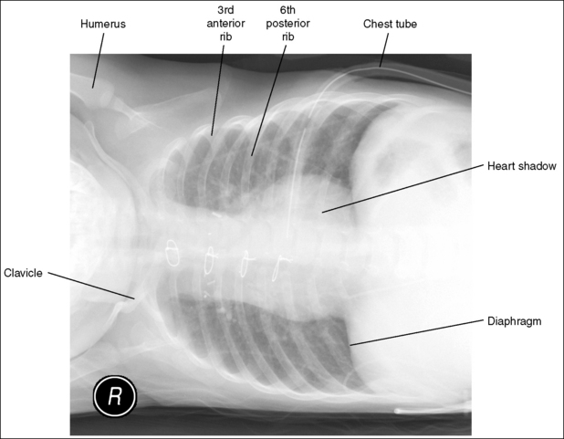
Contrast and density are adequate to visualize fluid levels or the presence of air within the pleural cavity.
• Positioning to demonstrate pleural air or fluid. The AP (lateral decubitus) projection is primarily used to confirm the presence of a pneumothorax or pleural effusion in the pleural cavity. To demonstrate the presence of air best, position the affected side of the thorax away from the bed or cart so that the air rises to the highest level in the pleural cavity. To demonstrate fluid in the pleural cavity best, position the affected side against the bed or cart. This positioning allows the fluid to move to the lowest level of the pleural cavity, away from the mediastinal structures (see Image 55).
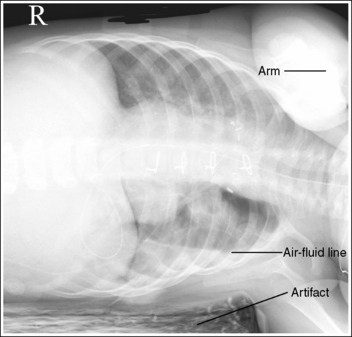
The fourth thoracic vertebra is at the center of the exposure field. The upper airway, lungs, mediastinal structures, and costophrenic angles are included within the collimated field.
• With the neonate or infant positioned on the lateral side that best demonstrates the condition of interest, place an 8- × 10-inch (18- × 24-cm) lengthwise IR against the patient's posterior surface and position the chest in the middle of the IR by elevating the patient on a radiolucent sponge. Center a horizontal central ray to the midsagittal plane at the level of the mammary line for neonates and small infants (Figure 3-56). A larger IR and slightly inferior centering may be needed for larger infants. This IR and central ray placement centers the lung field on the image, permitting tight collimation on all sides of the lungs. Open the longitudinal collimation to include the upper airway (infant's bottom lip) and costophrenic angles (tenth posterior rib), and transversely collimate to within 0.5 inch (1.25 cm) of the lateral skin line.
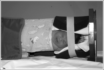
The chest demonstrates an AP projection. The distances from the vertebral column to the sternal ends of the clavicles are equal, and the lengths of the corresponding right and left posterior ribs are equal.
• To avoid chest rotation, align the shoulders, the posterior ribs, and the posterior pelvic wings perpendicularly to the bed or cart on which the neonate or infant is lying. This alignment positions the patient's shoulders and lungs at equal distances from the IR. Position the head straight ahead without rotation. The chest typically rotates in the same direction as the infant's head.
• Detecting chest rotation. Chest rotation is detected by evaluating the distance between the vertebral column and the sternal ends of the clavicles and by comparing the length of the right and left inferior posterior ribs. The sternal clavicular end that is superimposed over the least amount of the vertebral column, along with the side of the chest that demonstrates the longest inferior posterior ribs, represents the side of the chest toward which the infant is rotated (see Image 52).
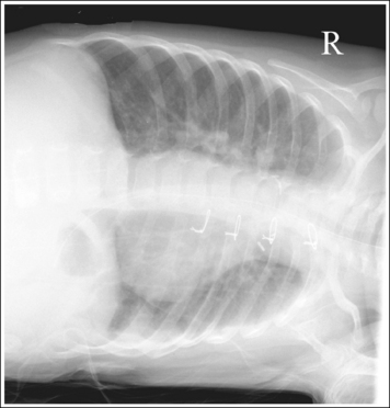
The chin and arms are situated outside the lung field, and the lateral aspects of the clavicles are projected upward.
• To prevent the chin from being superimposed over the lung apices on the image, elevate the chin until the face is facing forward and the neck is in a neutral position (see Image 53). Placing the arms upward toward the patient's head positions them away from the lung field and projects the lateral clavicles in an upward position (see Image 54).
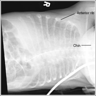
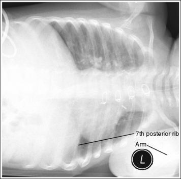
The anterior ribs are projecting downward, and the posterior ribs demonstrate a gentle, bowed downward contour.
• The neonate or infant AP (lateral decubitus) chest projection tends to have a lordotic appearance because of the lack of kyphotic thoracic curvature seen in adults. To reduce this lordotic appearance, align the central ray perpendicularly to the midcoronal plane and center the central ray at the level of the mammary line. Because the chest in neonates and infants is shorter than in adults, a common error is to center the central ray too inferiorly, resulting in an increase in the lordotic appearance.
• A neonate or infant AP (lateral decubitus) chest projection that demonstrates an excessively lordotic appearance will demonstrate cephalically projected anterior ribs and posterior ribs without their gentle, cephalically bowed appearance (see Image 53).
Eight posterior ribs are demonstrated above the diaphragm and the lungs demonstrate a fluffy appearance, with linear-appearing connecting tissue, indicating full lung aeration for the neonate or infant chest image.
The lung field positioned against the bed or cart is demonstrated without superimposition of the bed or cart pad. The midsagittal plane is demonstrated without lateral tilting.
• Elevating the neonate or infant on a radiolucent sponge prevents the chest from sinking into the cart pad. When the body is allowed to sink into the cart pad, artifact lines are seen superimposed over the lateral lung field of the side adjacent to the cart. Because fluid in the pleural cavity gravitates to the lowest level, it is in this area that the fluid will be demonstrated, and superimposition of the cart pad and lower lung field may obscure fluid that has settled in the lowest level. Position the neonate or infant's entire body on the radiolucent sponge to align the midsagittal plane parallel with the bed or cart, preventing lateral tilting (see Image 55).
Neonate and Infant Anteroposterior (Lateral Decubitus) Chest Projection Analysis
The left sternal clavicular end is demonstrated farther from the vertebral column than the right sternal clavicular end, and the left posterior ribs are longer than the right. The patient's head is turned, and the thorax is rotated toward the left side.
Correction
Rotate the patient's face to a forward position, and rotate the thorax toward the right side until the midcoronal plane is parallel with the IR and perpendicular to the central ray.
Analysis
The chest demonstrates an excessively lordotic appearance. The anterior ribs are projecting cephalically, and the posterior ribs do not demonstrate the slight cephalically bowed contour but are horizontal. The central ray was centered inferiorly to T6. The right inferior ribs are longer than the left posterior ribs. The patient was rotated toward the right side. The chin is superimposed over the apices and upper airway.
Correction
Move the central ray superiorly to align it with the upper thorax better. A 5-degree caudal angle may also be added to help align the central ray and thorax better. Rotate the patient toward the left side until the shoulders and the posterior ribs are at equal distances to the IR. Elevate the chin until it is positioned outside the collimated field.
Analysis
Seven posterior ribs are demonstrated above the diaphragm. Full lung aeration was not accomplished. The left arm is superimposed over a small portion of the left lateral lung field. The right clavicle is horizontal. The arms were not brought upward by the patient's head.
Correction
If possible, take the exposure after the patient takes a deep inspiration. If the patient is on a conventional ventilator, expose the image when the manometer is at it highest level, indicating a deep inspiration. Raise the patient's arms; bring them next to the patient's head.
Analysis
The device on which the patient is elevated is demonstrated adjacent to the left lateral lung field. Because the patient has not sunk into this device, it is not superimposed over the lateral lung field and is acceptable. The patient's upper midsagittal plane is laterally tilted toward the left side. The patient's upper thorax was allowed to hang over the elevating device. The patient's right arm is obscuring the lateral apical area. The right arm was not elevated to a position near the patient's head.
CHILD CHEST: ANTEROPOSTERIOR AND POSTEROANTERIOR PROJECTION (RIGHT OR LEFT LATERAL DECUBITUS POSITION)
See Figures 3-57 and 3-58.
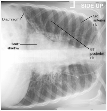
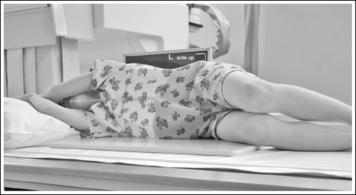
The analysis of AP (lateral decubitus) chest projections in children is the same as that of infant or adult AP (lateral decubitus) chest projections (see earlier). The size of the child determines the criterion that best meets the situation. For a discussion on the topics needed to analyze Image 56, refer to the discussion of AP-PA (lateral decubitus) chest projections earlier in this chapter.
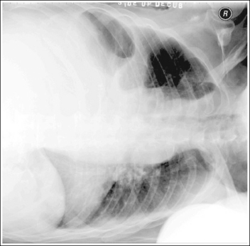
Child Anteroposterior-Posteroanterior (Lateral Decubitus) Chest Projection Analysis
The left sternal clavicular end is superimposed over the vertebral column, the posterior ribs on the right side demonstrate the greater length, and the arms are superimposed over the left lateral lung apex. The patient was rotated toward the right side, and the left arm was at a 90-degree angle with thorax.
ABDOMEN
The following image analysis criteria are used for all adult and pediatric abdomen projections and should be considered when completing the analysis for each abdominal projection presented in this chapter (Box 3-11).
Voluntary and Involuntary Motion
Two types of motion may be evident on an abdominal image, voluntary and involuntary. Voluntary motion is caused by breathing or moving during the exposure. It can be controlled by explaining to the patient the importance of holding still, making the patient as comfortable as possible on the imaging table, and using the shortest possible exposure time. On an image, voluntary motion can be identified as blurred bony cortices and gastric and intestinal gases (see Image 57). Involuntary motion is caused by the peristaltic activity of the stomach or small or large intestine. This movement is considered involuntary because the patient cannot control this movement, as with breathing. The only means of decreasing the blur caused by involuntary motion is to use the shortest possible exposure time and, in some cases, this is not good enough. Involuntary motion can be identified on abdominal images as sharp bony cortices and blurry gastric and intestinal gases (see Image 58).
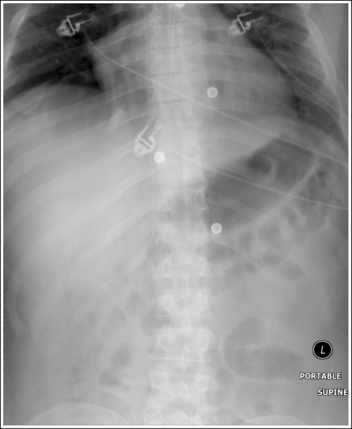
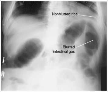
Visibility of Details
Beam penetration, contrast, and density are adequate on adult abdominal images when the collections of fat that outline the psoas major muscles and kidney as well as the bony structures of the inferior ribs and transverse processes of the lumbar vertebrae are demonstrated.
An optimal kVp technique, as shown in Table 3-3, sufficiently penetrates the soft tissue and bony structures of the abdomen. This kVp setting enhances the subtle radiation absorption differences among the fat, gas, muscles, and solid organs, which mainly consist of water. Because soft tissue abdominal structures are similar in atomic number and density, whether two soft tissue structures that border each other are visible or not depends on their arrangement with respect to the gas and fat collections that lie next to them, around them, or within them. These same gas and fat collections are used to identify diseases and masses within the abdomen. The presence or absence of gas, as well as its amount and location within the intestinal system, may indicate a functional, metabolic, or mechanical disease, whereas routinely seen collections of fat may be displaced or obscured with organ enlargement or mass invasion. Use a high-ratio grid to reduce the scatter radiation that reaches the IR, thereby reducing fog, increasing the visibility of the recorded details, and providing a higher contrast image. To obtain optimal density, set a manual mAs based on the patient's abdominal thickness or choose all three AEC chambers.
The soft tissue structures that can be outlined if appropriate image density and contrast have been obtained on an AP abdominal projection are the psoas major muscles and kidneys. The psoas major muscles are located laterally to the lumbar vertebrae. They originate at the first lumbar vertebra on each side and extend to the corresponding lesser trochanter. On an AP abdominal projection, the psoas major muscles are visible as long, triangular, soft tissue shadows on each side of the vertebral bodies. The kidneys are found in the posterior abdomen and are identified on the image as bean-shaped densities located on each side of the vertebral column 3 inches (7.5 cm) from the midline. The upper poles of the kidney lie on the same transverse level as the spinous process of the eleventh thoracic vertebra, and the lower poles lie on the same transverse level as the spinous process of the third lumbar vertebra. The right kidney is usually demonstrated approximately 1 inch (2.5 cm) inferior to the left kidney because of its location beneath the liver. Occasionally a kidney may be displaced inferiorly (nephroptosis) to this location, because it is not held in place by adjacent organs or its fat covering; this condition is most often seen in thin patients.
Adjusting Technique for Specific Patient Conditions
The routine manually set exposure factors obtained from the AP body measurement of patients with suspected large amounts of bowel gas may overexpose areas of the abdomen that are overlaid with gas (see Image 59). (The patient measures the same whether gas or dense soft tissue causes the thickness.) This increased image density results from the low density (number of atoms per given area) characteristic of gas. As the radiation passes through the patient's body, fewer photons are absorbed where gas is located than where dense soft tissue is present. To compensate for this situation, decrease the exposure (mAs) 30% to 50% or the kVp 5% to 8% from the routinely used manual technique before the image is taken. An underexposed image may result when patients have ascites, obesity, bowel obstructions, or soft tissue masses. This is because sections of the abdomen that normally contain gas or fat do not, resulting in an increase in the density of the soft tissue. To compensate for this situation, increase the exposure (mAs) 30% to 50% or the kVp 5% to 8% from the routinely used technique before the image is taken.
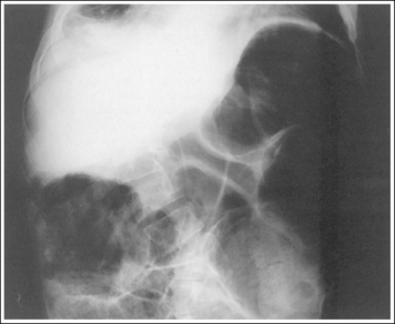
Pediatric Abdomen
For the pediatric patient contrast, density, and penetration should be adequate to demonstrate the diaphragm, bowel gas pattern, and faint outline of bony structures. An optimal kVp technique, as shown in Table 3-3, sufficiently penetrates the bowel gas pattern and faintly outlines the bony structures. In infants and young children, it is difficult to differentiate between the small and large bowels. The gas loops tend to look the same. Because little intrinsic fat is present, the abdominal organs (such as kidneys) are not well defined.
ABDOMEN: AP PROJECTION (SUPINE AND UPRIGHT)
See Figures 3-59 and 3-60 and Box 3-12.
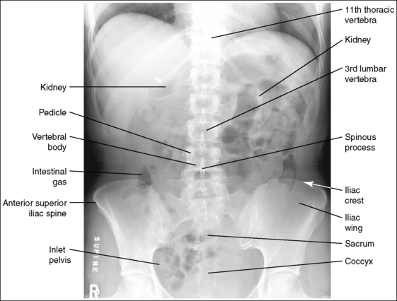
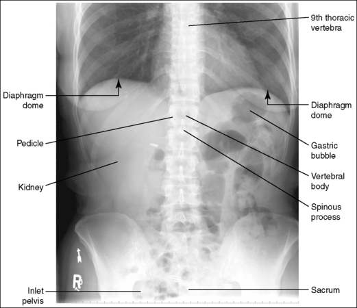
Density is uniform across the abdomen.
• Excessive abdominal soft tissue. When an upright AP abdomen projection is taken on a patient with excessive abdominal soft tissue, the soft tissue often drops down and forward. This movement results in a larger AP measurement at the lower abdominal level than at the upper abdominal level. For such patients, use two crosswise IRs to include all the abdominal structures, and take measurements of the lower and upper abdominal areas to ensure that accurate image density of each area will be obtained.
The abdomen image demonstrates an AP projection. The spinous processes are aligned with the midline of the vertebral bodies, and the distance from the pedicles to the spinous processes is the same on both sides. The sacrum is centered within the inlet of pelvis and is aligned with the symphysis pubis.
• To obtain a supine abdomen projection, place the patient supine on the radiographic table. Position the shoulders and anterosuperior iliac spines at equal distances from the tabletop to prevent rotation, and draw the patient's arms away from the abdominal area to prevent them from being superimposed on the abdominal region (Figure 3-61).
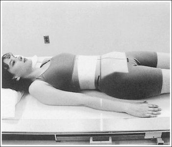
• An upright abdomen projection is obtained by placing the patient against an upright imaging tabletop. Position the shoulders and anterosuperior iliac spines at equal distances from the tabletop to prevent rotation, and draw the patient's arms away from the abdominal area to prevent them from being superimposed on the abdominal region (Figure 3-62).
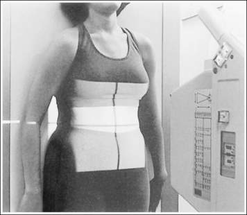
• Demonstrating intraperitoneal air: For intraperitoneal air to be demonstrated best, the patient should be positioned upright for 5 to 20 minutes before the image is taken. This allows enough time for the air to move away from the soft tissue abdominal structures and rise to the level of the diaphragms (Figure 3-63). If a patient has come to the imaging department for a supine and upright abdominal series, begin with the upright image if the patient is ambulatory (able to walk) or transported by wheelchair. An ambulatory or wheelchair-using patient has been upright long enough for the air to rise, so it is not necessary to wait to take the image.
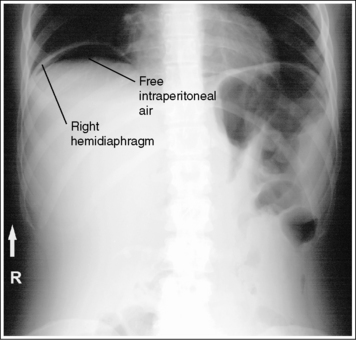
• Detecting abdominal rotation: Rotation of an AP abdomen projection can decrease the visualization of fat lines that surround abdominal structures. For example, the psoas lateral muscles are outlined because of the fat that lies next to them. When the patient is rotated to one side, this fat shifts from lateral to anterior or posterior with respect to the muscle. The shift eliminates the subject contrast difference that exists when the muscle and fat are separated, hindering the usefulness of the psoas major muscles as diagnostic indicators. The upper and lower lumbar vertebrae can demonstrate rotation independently or simultaneously, depending on which section of the body is rotated. If the patient's thorax was rotated but the pelvis remained in an AP projection, the upper lumbar vertebrae and abdominal cavity demonstrate rotation. If the patient's pelvis was rotated but the thorax remained in an AP projection, the lower vertebrae and abdominal cavity demonstrate rotation. If the patient's thorax and pelvis were rotated simultaneously, the entire lumbar column and abdominal cavity demonstrate rotation. Rotation is effectively detected on an AP abdomen projection by comparing the distance from the pedicles to the spinous processes on each side and by evaluating the centering of the sacrum within the inlet pelvis. If the distance from the pedicles to the spinous processes is greater on one side of the vertebrae than on the other, or if the sacrum is rotated toward one side of the inlet, pelvic rotation is present (see Images 60 and 61). The side with the smaller distance between the pedicles and spinous processes and toward which the sacrum is rotated is the side of the patient positioned farther from the tabletop and IR.
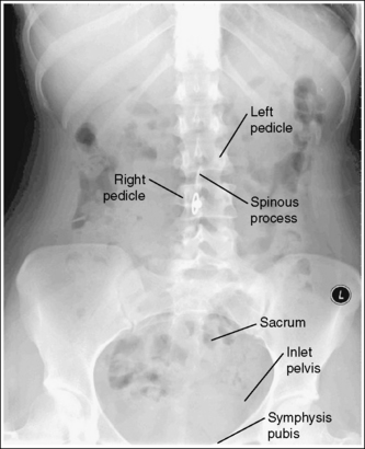
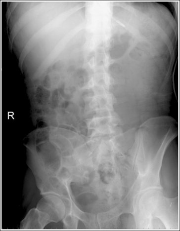
• Distinguishing abdominal rotation from scoliosis. In patients with scoliosis, the lumbar bodies may appear rotated because of the lateral twisting of the vertebrae. Scoliosis of the vertebral column can be very severe, demonstrating a large degree of lateral deviation, or it can be subtle, demonstrating only a small degree of deviation. Severe scoliosis is very obvious and is seldom mistaken for patient rotation, whereas subtle scoliotic changes can be easily mistaken for patient rotation (see Image 62). Although both demonstrate unequal distances between the pedicles and spinous processes, clues that can be used to distinguish subtle scoliosis from rotation are present. The long axis of a rotated vertebral column remains straight, whereas the scoliotic vertebral column demonstrates lateral deviation. When the lumbar vertebrae demonstrate rotation, it has been caused by the rotation of the upper or lower torso. The middle lumbar vertebrae (L3 and L4) cannot rotate unless the lower thoracic vertebrae or upper or lower lumbar vertebrae are also rotated. On the scoliotic image, the middle lumbar vertebrae may demonstrate rotation without corresponding upper or lower vertebral rotation. This constitutes an acceptable image for a patient with this condition.
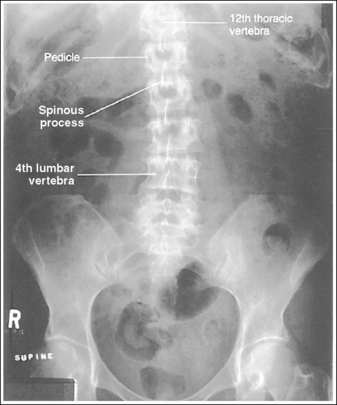
The long axis of the lumbar vertebral column is aligned with the long axis of the collimated field.
• Aligning the long axis of the lumbar vertebral column with the long axis of the collimated field ensures that the lateral abdominal cavity will not be clipped. To obtain proper upper abdominal alignment, align the xiphoid with the collimator's longitudinal light line. To obtain proper lower abdominal alignment, find the point midway between the patient's palpable anterior superior iliac spines (ASISs); then align this point with the collimator's longitudinal light line. Do not assume that the patient's navel is positioned directly above the vertebral column. Often it is shifted to one side.
The image was taken on expiration, and the diaphragm dome is located superior to the ninth posterior ribs.
• From full inspiration to expiration, the diaphragm position moves from an inferior to a superior position. This movement also changes the pressure placed on the abdominal structures. On full expiration, the right side of the diaphragm dome is at the same transverse level as the eighth or ninth thoracic vertebra, whereas on inspiration, it may be found at the same transverse level as the ninth posterior rib (see Image 63). If the abdominal image is taken on inspiration, the inferior placement of the diaphragm places pressure on the abdominal organs, resulting in less space in the peritoneal cavity and greater abdominal density. Underexposed images may also result with full inspiration on the upper abdomen image when two crosswise images are needed and the three AEC chambers are chosen, because the outside AEC chambers will be positioned beneath the lungs instead of abdominal structures.
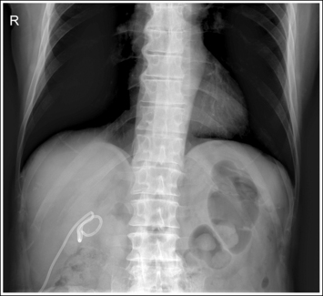
Supine position: The fourth lumbar vertebra is at the center of the exposure field. The spinous process of the eleventh thoracic vertebra, the lateral body soft tissues, the iliac wings, and the symphysis pubis are included within the collimated field.
• Including the spinous process of the eleventh thoracic vertebra ensures that the kidneys, tip of liver, and spleen, all of which lie inferior to it, will be present on the image. The symphysis pubis ensures that the inferior border of the peritoneal cavity is included on the image (see Image 64). To position the fourth lumbar vertebra in the center of the collimated field, use a 40- to 48-inch (102- to 120-cm) SID. Center a perpendicular central ray with the patient's midsagittal plane at the level of the iliac crest for female patients and at a level 1 inch (2.5 cm) inferior to the iliac crest for male patients to allow for the difference in size and longitudinal dimension between the female and male pelves.
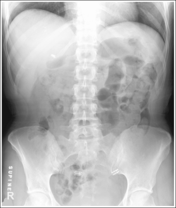
• Centering the central ray in males and females. The centering determination measurements for male patients were taken from several male and female pelvic images, because of the following: (1) the patient is positioned in the same manner for a pelvic image as for an AP abdomen projection; (2) the magnification factors (SID and OID) are identical to those used for an AP abdominal image; and (3) all pelvic anatomy was included and could be easily measured. The only difference in setup procedure between AP pelvis and AP abdomen projections is the centering of the central ray. Although the superior centering used for the AP abdomen projection projects the anteriorly located pelvic structures slightly more inferiorly than they appear on an AP pelvis projection, the influence is the same on all abdominal IRs and affects the male and female pelves in the same manner. A measurement of each pelvic image was taken from the most superiorly located surface of the right iliac crest to the most inferior aspect of the right obturator foramen. Although slight variations of approximately 0.25 inch (0.6 cm) did exist in each gender, the average female measurement was 8.5 inches (21.25 cm) and the average male measurement was 9.5 inches (24 cm). Because the IR length used for AP abdomen projections is 17 inches (43 cm) and the pelvis is to fit on the lower half, or 8.5 inches (21.25 cm), one can understand why accurate central ray placement is important to include the needed structures.
• IR size and direction. A 14- × 17-inch (35- × 43-cm) lengthwise IR should be adequate to include all the required anatomic structures on sthenic and asthenic patients, as long as the transverse abdominal measurement is less than 14 inches (35 cm).
If the spinous process of the eleventh thoracic vertebra is not included on this image, take a second image using an 11- × 14-inch (28- × 35-cm) crosswise IR. It is necessary for the second image to include approximately 2 to 3 inches (5 to 7.5 cm) of the same transverse section of the peritoneal cavity imaged on the first image to ensure that no middle peritoneal information has been excluded. The top of the IR should extend to the patient's xiphoid, which is at the level of the tenth thoracic vertebra, to make sure that the spinous process of the eleventh thoracic vertebra is included. The longitudinal collimated field should remain fully open for both IRs. Transversely, collimate to within 0.5inch (1.25 cm) of the patient's lateral skin line.
Use two 14- × 17-inch (35- × 43-cm) crosswise IRs on hypersthenic patients, and on patients who have a transverse abdominal measurement of 14 inches (35 cm) or greater, to include all the necessary anatomic structures. Take the first image with the central ray centered to the midsagittal plane at a level halfway between the symphysis pubis and ASIS. Position the bottom of the second IR so that it includes 2 to 3 inches (5 to 7.5 cm) of the same transverse section of the peritoneal cavity imaged on the first image to ensure that no middle peritoneal information has been excluded. The top of the IR should extend to the patient's xiphoid, which is at the level of the tenth thoracic vertebra, to make sure that the spinous process of the eleventh thoracic vertebra is included.
• Gonadal shielding: Use gonadal shielding for supine images on all male patients and on female patients if two IRs are required and the upper abdomen is being imaged. Do not shield female patients if the lower abdomen is being imaged, because the shield may obscure needed information.
Upright position: The third lumbar vertebra is at the center of the exposure field. The diaphragm, the ninth thoracic vertebra, the lateral body soft tissue, and the iliac wings are included within the collimated field.
• Positioning and central ray. The upright AP abdomen projection is most often used to evaluate the peritoneal cavity for intraperitoneal air. For intraperitoneal air to be demonstrated, the diaphragm must be included in its entirety, because the air would be located directly inferior to the domes of the diaphragm (see Figure 3-63). When the image is taken on expiration, including the ninth thoracic vertebra will ensure demonstration of the diaphragm. To include the ninth thoracic vertebra at the top of the image and to center the third thoracic vertebra to the center of the collimated field, place the top of the IR (not the top of the collimator's light field) at a level of the axilla for the sthenic patient, slightly higher for the hypersthenic patient, and slightly lower for the asthenic patient. Use a 40- to 48-inch (102- to 120-cm) SID. Center a perpendicular central ray with the midsagittal plane and IR center. An upright AP abdomen projection that does not include the entire diaphragm should be retaken (see Image 65).
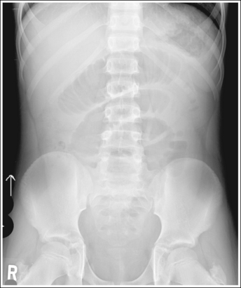
• IR size and direction: A 14- × 17-inch (35- × 43-cm) lengthwise IR is adequate to include all the required anatomic structures on the sthenic or asthenic patient, as long as the patient's transverse abdominal measurement is less than 14 inches (35 cm). Open the longitudinal collimated field the full 17-inch (43-cm) field size and transversely collimate to within 0.5 inch (1.25 cm) of the lateral skin line. Use two 14- × 17-inch (35- × 43-cm) crosswise IRs on hypersthenic patients, and on sthenic and asthenic patients who have transverse abdominal measurement of 14 inches (35 cm) or greater, to include all the necessary anatomic structures. Take the first image with the top of the IR positioned as described earlier. Place the top of the second IR so that it will include 2 to 3 inches (5 to 7.5 cm) of the same transverse section of the peritoneal cavity imaged on the first image to ensure that no middle peritoneal information has been excluded. Center the central ray to the midsagittal plane for both images.
• Gonadal shielding: Use gonadal shielding for upright images on all male abdomen projections and female patients if two IRs are required and the upper abdomen is being imaged. Do not shield female patients when the lower abdomen is imaged because the shield may obscure needed information.
Anteroposterior Abdomen Projection Analysis
The ribs and intestines are blurred, indicating that the patient moved and/or breathed during the exposure. The symphysis pubis is not included on the image. The central ray was positioned too superiorly. The lateral soft tissue is not entirely included on the image. Two crosswise images should have been taken.
Correction
Instruct the patient to halt respiration during the exposure. Using a short exposure time will also help if the patient has difficulty holding still. Repeat the examination using two crosswise IRs, making certain that the lower image includes the inferior peritoneal cavity.
Analysis
This is the upper image of a crosswise AP abdomen projection. The cortical outlines of the ribs and vertebral column are well defined without blur, whereas the intestinal structures demonstrate blur. This represents involuntary motion.
Analysis
This abdomen projection is from a hypersthenic patient who had an excessive amount of bowel gas. In an attempt to demonstrate the areas superimposed with bowel gas, the exposure (mAs) was decreased. The decrease resulted in an underexposed area beneath the right diaphragm.
Correction
If this abdominal area is of importance, a second image should be taken with increased exposure. If the indication for the examination is to evaluate bowel gas, the image is acceptable.
Analysis
The sacrum is not aligned with the symphysis pubis but is situated closer to the right hip, and the distance from the right pedicles to the spinous processes is less than the distance from the left pedicles to the spinous processes. The patient was rotated toward the left side.
Correction
Rotate the patient toward the right side until the shoulders and ASISs are positioned at equal distances from the IR.
Analysis
The sacrum is not aligned with the symphysis pubis but is situated closer to the left, and the distance from the left pedicles to the spinous processes is less than the distance from the right pedicles to the spinous processes. The patient was rotated toward the right side.
Correction
Rotate the patient toward the left side until the shoulders and ASISs are positioned at equal distances.
Analysis
The vertebral column deviates laterally at the level of the second through fourth lumbar vertebrae, the sacrum is centered within the inlet pelvis, and the distances from the pedicles to the spinous processes of the twelfth thoracic vertebra and fifth lumbar vertebra are equal. The vertebral column demonstrates subtle spinal scoliosis.
Correction
No correction movement is required for scoliosis. An AP abdomen projection of a patient with scoliosis appears rotated.
Analysis
The diaphragm dome is located inferiorly to the ninth posterior ribs. The examination was taken on full inspiration.
Analysis
The symphysis pubis is not included on the image. The central ray was centered too superiorly.
Correction
Because this is a male patient, center the central ray 1 inch (2.5 cm) inferior to the iliac crest.
ABDOMEN: ANTEROPOSTERIOR PROJECTION (LEFT LATERAL DECUBITUS POSITION)
See Figure 3-64 and Box 3-13.
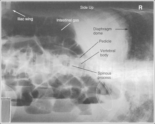
An arrow or “word” marker, indicating that the right side of the patient was positioned up and away from the imaging table or cart, is present on the image.
• Place an arrow or “word” marker indicating which side of the patient was positioned away from the tabletop or cart and in the collimated field.
Density is uniform across the abdomen.
• Using a wedge-compensating filter. When an AP (lateral decubitus) abdomen projection from a patient with excessive abdominal soft tissue is taken, the soft tissue often drops toward the tabletop or cart. This movement results in a smaller AP measurement at the elevated right side than at the left side, which is positioned closer to the tabletop or cart. To compensate for this thickness difference, a wedge-compensating filter may be used. The wedge filter absorbs some of the x-ray photons before they reach the patient, thereby decreasing the number of photons exposing the IR where the filter is located. The thick end of the wedge filter absorbs more photons than the thin end. When a wedge-compensating filter is used, attach it to the x-ray collimator head, with the thick end positioned toward the patient's right side and the thin end toward the left side. The collimator light projects a shadow of the compensating filter onto the patient. Position the shadow of the thin end at the level of the thickest part of the abdomen, allowing the thick end to extend toward the right side. Then use a technique that will accurately expose the thickest abdominal region. The wedge-compensating filter should absorb the needed photons to prevent overexposure of the thinner abdominal region. When the filter has been accurately positioned, radiographic density is uniform throughout the abdominal structures. Positioning the filter too close to or too far away from the thickest part of the abdomen results in an overexposed or underexposed area on the image, respectively.
The abdomen demonstrates an AP projection. The spinous processes are aligned with the midline of the vertebral bodies, the distance from the pedicles to the spinous processes is the same on both sides, and the iliac wings are symmetrical.
• An AP (lateral decubitus) abdomen projection is obtained by placing the patient in a left lateral recumbent position on the tabletop or cart, with the back resting against a grid cassette or the upright IR holder. Because intraperitoneal air migrates to the highest position, which is typically the elevated diaphragm or iliac wing, the left lateral position is chosen to position the gastric bubble away from the elevated diaphragm. To avoid rotation, align the shoulders, the posterior ribs, and the posterior pelvic wings perpendicular to the tabletop or cart (Figure 3-65). Accomplish this alignment by resting your extended flat hand against each, respectively, and then adjusting the patient's rotation until your hand is positioned perpendicular to the tabletop or cart. It is most common for a patient to rotate the elevated thorax and pelvic wing anteriorly. A pillow or other support placed between the patient's knees may help eliminate this forward rotation.
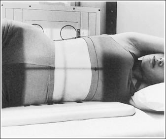
• Demonstrating intraperitoneal air. The AP (lateral decubitus) projection is primarily used to confirm the presence of intraperitoneal air. For intraperitoneal air to be demonstrated best, the patient should be left in this position for 5 to 20 minutes before the image is taken, allowing enough time for the air to move away from the soft tissue abdominal structures and rise to the level of the right diaphragm or iliac wing (Figure 3-66). To eliminate long waiting periods for patients who are scheduled to have an AP (lateral decubitus) abdomen, have them transported to the imaging department in the left lateral decubitus position.
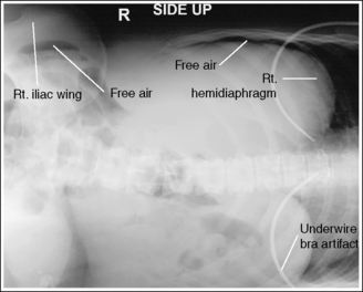
Figure 3-66 AP (lateral decubitus) abdomen projection demonstrating free intraperitoneal air under right hemidiaphragm and at right iliac wing.
• Detecting abdominal rotation. The upper and lower lumbar vertebrae can demonstrate rotation independently or simultaneously, depending on which section of the body is rotated. If the patient's thorax is rotated but the pelvis remains in an AP projection, the upper lumbar vertebrae and abdominal cavity demonstrate rotation. If the patient's pelvis is rotated but the thorax remains in an AP projection, the lower vertebrae and abdominal cavity demonstrate rotation. If the patient's thorax and pelvis are rotated simultaneously, the entire lumbar column and abdominal cavity demonstrate rotation.
Rotation is effectively detected on an AP abdominal projection by comparing the distance from the pedicles to the spinous processes on each side and the symmetry of the iliac wings. If the distance from the pedicles to the spinous processes is greater on one side of the vertebrae than on the other side, the side with the smaller distance between the pedicles and spinous processes was the side of the patient positioned farther from the IR. If the iliac wings are not symmetrical, the wing demonstrating the smallest area is on the side of the patient positioned farther from the IR (see Image 66).
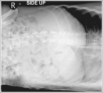
Image 66
• Distinguishing rotation from scoliosis. In images from patients with spinal scoliosis the lumbar bodies may appear rotated because of the lateral twisting of the vertebrae. An image on a patient with spinal scoliosis and a rotated decubitus abdomen demonstrates unequal distances between the pedicles and spinous processes. Clues are present that can be used to distinguish scoliosis from rotation. The long axis of a rotated vertebral column remains straight, whereas the scoliotic vertebral column demonstrates lateral deviation. When the lumbar vertebrae demonstrate rotation, it has been caused by the rotation of the upper or lower torso. The middle lumbar vertebrae (L3 and L4) cannot rotate unless the lower thoracic vertebrae or the upper or lower lumbar vertebrae are also rotated. On the scoliotic decubitus abdominal image, the middle lumbar vertebrae may demonstrate rotation without corresponding upper or lower vertebral rotation.
The image was taken on expiration. The diaphragm domes are located superiorly to the ninth posterior rib.
• From full inspiration to expiration, the diaphragm moves from an inferior to a superior position. This movement also changes the pressure exerted on the abdominal structures. On full expiration the superior portion of the right upper diaphragm dome is at the same transverse level as the eighth or ninth thoracic vertebrae, whereas on inspiration it may be found at the same transverse level as the ninth posterior rib. The left diaphragm is approximately 0.5 inch (1.25 cm) lower than the right diaphragm on both inspiration and expiration. When the AP (lateral decubitus) abdomen projection is taken on expiration, less pressure is exerted on the peritoneal contents and greater space exists in the peritoneal cavity. If the AP (lateral decubitus) abdomen projection is taken on inspiration, the inferior placement of the diaphragm puts pressure on the abdominal organs, resulting in less space in the peritoneal cavity and greater abdominal density.
The third lumbar vertebra is at the center of the exposure field. The right hemidiaphragm, ninth thoracic vertebra, right lateral body soft tissue, and iliac wing are included within the collimated field.
• The AP (lateral decubitus) abdomen projection is most often used to evaluate the peritoneal cavity for intraperitoneal air. To demonstrate intraperitoneal air, the right hemidiaphragm and iliac wing must be included. In the left lateral decubitus position, intraperitoneal air will rise to the highest level. In most patients the intraperitoneal air moves to the right upper quadrant just below the diaphragm, between the liver and abdominal wall. One exception to this placement of intraperitoneal air occurs in women with wide hips, whose highest level within the peritoneal cavity is just over the iliac bone (see Figure 3-66). Failure to include the right hemidiaphragm and iliac wing on the image will compromise an intraperitoneal air diagnosis (see Image 67).
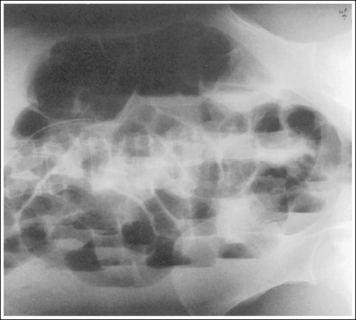
Image 67
• IR size and direction. A 14- × 17-inch (35- × 43-cm) IR positioned lengthwise with respect to the patient should be adequate to include all the anatomic structures in asthenic and sthenic patients, as long as the transverse abdominal measurement is less than 14 inches (35 cm). To place the ninth thoracic vertebra at the top of the image and to center the third thoracic vertebra within the center of the collimated field, place the top of the IR at a level 2.5 inches (6.25 cm) superior to the xiphoid (see Image 39). Use a 40- to 48-inch (102- to 120-cm) SID, and center a horizontal central ray with the midsagittal plane. Open the longitudinally and transversely collimated fields to the full 14- × 17-inch (35- × 43-cm) size. If the right lateral soft tissue does not appear to be included with this positioning, use two crosswise IRs instead of one lengthwise IR.
Use two 14- × 17-inch (35- × -43-cm) IRs positioned crosswise with respect to the patient to include all the necessary anatomic structures in the hypersthenic patient and in sthenic and asthenic patients who have transverse abdominal measurements of 14 inches (35 cm) or greater. Take the first image with the top of the IR placed at a level 2.5 inches (6.25 cm) superior to the xiphoid. Position the top of the second IR such that it includes approximately 2 to 3 inches (5 to 7.5 cm) of the same transverse section of the peritoneal cavity imaged on the first image to ensure that no middle peritoneal information has been excluded. For both images, center a horizontal central ray with the midsagittal plane.
• Gonadal shielding. Use gonadal shielding on all male abdominal images and on female patients if two IRs are required and the upper abdomen is being imaged. Do not shield a female patient if the lower abdomen is imaged because the shield may obscure needed information.
AP (Lateral Decubitus) Abdomen Projection Analysis
The right iliac wing is narrower than the left iliac wing, and the distance from the right pedicles to the spinous processes is less than the distance from the left pedicles to the spinous processes. The patient's right side was positioned farther from the IR than the left side.
Correction
Rotate the patient's right side toward the IR until the shoulders and the ASISs are positioned at equal distances from the IR.
NEONATE AND INFANT ABDOMEN: ANTEROPOSTERIOR PROJECTION (SUPINE)
See Figure 3-67 and Box 3-14.
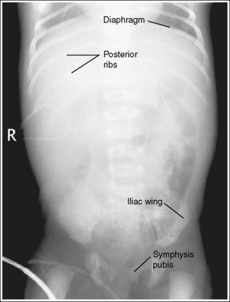
The abdomen demonstrates an AP projection. The right and left inferior posterior ribs and the iliac wings are symmetrical.
• An AP abdomen projection is obtained by placing the neonate or infant in a supine position with the IR centered beneath the abdomen. To avoid rotation, align the shoulders and the posterior pelvic wings at equal distances from the IR (Figure 3-68).
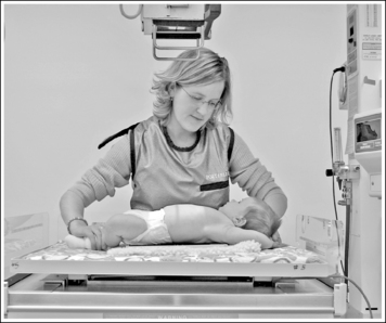
• Detecting abdominal rotation. The upper and lower lumbar vertebrae can demonstrate rotation independently or simultaneously, depending on which section of the body is rotated. If the patient's thorax is rotated but the pelvis remains in an AP projection, the upper lumbar vertebrae and abdominal cavity demonstrate rotation. If the patient's pelvis is rotated but the thorax remains in an AP projection, the lower vertebrae and abdominal cavity demonstrate rotation. If the patient's thorax and pelvis are rotated simultaneously, the entire lumbar column and abdominal cavity demonstrate rotation.
Rotation is effectively detected on an AP abdominal projection by comparing the symmetry of the inferior posterior ribs and the iliac wings (see Image 68). The ribs that demonstrate the longer length and the iliac wing demonstrating the greater width are on the side toward which the patient is rotated.
The image was taken on expiration. The diaphragm domes are superior to the eighth posterior rib.
• From full inspiration to expiration, the diaphragm moves from an inferior to a superior position. This movement also changes the pressure placed on the abdominal structures. On full expiration the diaphragm dome is above the eighth posterior rib. When the AP abdomen projection is taken on expiration, less pressure is exerted on the peritoneal contents and the space in the peritoneal cavity is greater. If the AP projection is taken on inspiration, the inferior placement of the diaphragm puts pressure on the abdominal organs, resulting in less space in the peritoneal cavity and greater abdominal density (see Image 68).
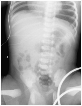
Image 68
• For neonates or infants being ventilated with a conventional ventilator, observe the ventilator's pressure manometer. The exposure should be taken when the manometer digital bar or analog needle moves to its highest position. If a high-frequency ventilator is being used, the exposure may be made at any time, because this ventilator maintains the lung expansion at a steady mean pressure without the bulk gas exchange of the conventional type.
The long axis of the lumbar vertebral column is aligned with the long axis of the collimated field.
• Aligning the long axis of the lumbar vertebral column with the long axis of the collimated field allows for tight transverse collimation (see Image 69).
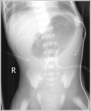
Image 69
The fourth lumbar vertebra is at the center of the exposure field. The diaphragm, abdominal structures, and symphysis pubis are included within the collimated field.
• IR size and centering. With the neonate or infant positioned in supine AP projection, center an 8- × 10-inch (18- ×24-cm), lengthwise IR beneath the neonate or infant. Center a perpendicular central ray to the midsagittal plane at a transverse level approximately 2 inches (5 cm) superior to the iliac crest. A larger IR and slightly inferior centering may be needed for larger infants. This IR and central ray placement centers the abdomen on the image, permitting tight collimation on all sides of the lungs. Open the longitudinal collimation to include the diaphragm (1 inch [2.5 cm] inferior to mammary line) and symphysis pubis, and transversely collimate to within 0.5 inch (1.25 cm) of the lateral skin line (see Image 70).
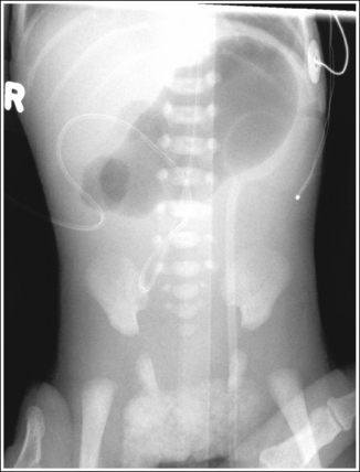
Image 70
• Gonadal shielding. Use gonadal shielding on all male abdominal images. Do not shield a female patient, because the shield may obscure needed information.
Neonate and Infant: Anteroposterior Abdomen Projection Analysis
The posterior ribs are longer on the right side than on the left, and the right iliac wing is wider than the left side posterior ribs. The diaphragm is at the level of the eighth posterior rib. The patient was rotated toward the right side, and the exposure was taken on inspiration.
Correction
Rotate the patient toward the left side until the shoulders and iliac wings are at equal distances to the IR, and expose the image after the patient exhales or the manometer is at its lowest level for conventional ventilators.
Analysis
The patient's upper vertebral column is tilted toward the right side. Tight collimation practices could not be followed.
Correction
Tilt the upper vertebral column toward the left side until the vertebral column is straight and aligned with the collimator's longitudinal light line. Increase transverse collimation to within 0.5 inch (1.25 cm) from skin line.
CHILD ABDOMEN: AP PROJECTION
See Figures 3-69 to 3-72.
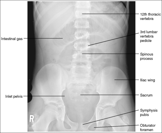
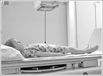
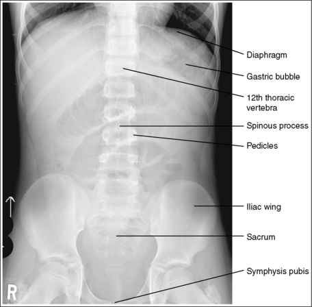
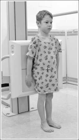
The analysis of child AP abdomen projections is the same as that of infant or adult AP abdomen projections (see earlier). The size of the child determines which criterion best meets the situation. For a discussion on topics needed to analyze Images 71 and 72 that follow, refer to the adult or infant abdominal discussion earlier in this chapter.
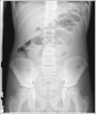
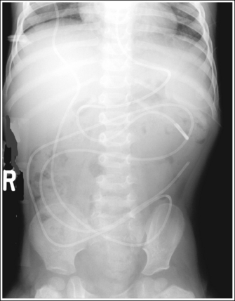
Child Anteroposterior Abdomen Projection Analysis
NEONATE AND INFANT ABDOMEN: ANTEROPOSTERIOR PROJECTION (LEFT LATERAL DECUBITUS POSITION)
See Figure 3-73 and Box 3-15.
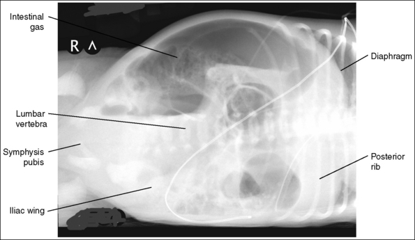
An arrow or “word” marker, indicating that the right side of the patient was positioned up and away from the bed or cart, is present on the image.
• Place an arrow or “word” marker indicating which side of the patient was positioned away from the tabletop or cart and in the collimated field.
• An AP (lateral decubitus) abdomen projection is obtained by placing the neonate or infant in a left lateral recumbent position on the bed or cart, with the posterior surface resting against a vertical IR. Because intraperitoneal air migrates to the highest position, which is typically the elevated diaphragm, the left lateral position is chosen to position the gastric bubble away from the elevated diaphragm. To avoid rotation, align the shoulders, the posterior ribs, and the posterior pelvic wings perpendicular to the bed or cart (Figure 3-74).
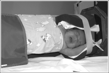
Figure 3-74 Proper patient positioning for neonate and infant AP (lateral decubitus) abdomen projection.
• Demonstrating intraperitoneal air. The left lateral decubitus position is primarily used to confirm the presence of intraperitoneal air. To demonstrate intraperitoneal air best, the patient should remain in this position for a few minutes to allow enough time for the air to move away from the soft tissue abdominal structures and rise to the level of the right diaphragm.
• Detecting abdominal rotation. The upper and lower lumbar vertebrae can demonstrate rotation independently or simultaneously, depending on which section of the body is rotated. If the patient's thorax is rotated but the pelvis remains in an AP projection, the upper lumbar vertebrae and abdominal cavity demonstrate rotation. If the patient's pelvis is rotated but the thorax remains in an AP projection, the lower vertebrae and abdominal cavity demonstrate rotation. If the patient's thorax and pelvis are rotated simultaneously, the entire lumbar column and abdominal cavity demonstrate rotation.
Rotation is effectively detected on an AP (lateral decubitus) abdomen projection by comparing the symmetry of the posterior ribs and the iliac wings (see Image 73). The ribs that demonstrate the longer length and the iliac wing demonstrating the greater width are present on the side toward which the patient is rotated.
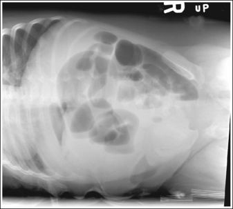
Image 73
The image was taken on expiration. The diaphragm domes are superior to the eighth posterior rib.
• For neonates or infants being ventilated with a conventional ventilator, observe the ventilator's pressure manometer. The exposure should be taken when the manometer digital bar or analog needle moves to its highest position. If a high-frequency ventilator is being used, the exposure may be made at any time, because this ventilator maintains the lung expansion at a steady mean pressure without the bulk gas exchange of the conventional type.
If the AP (lateral decubitus) projection is taken on inspiration, the inferior placement of the diaphragm puts pressure on the abdominal organs, resulting in less space in the peritoneal cavity and greater abdominal density.
The fourth lumbar vertebra is at the center of the exposure field. The diaphragm and abdominal structures are included within the collimated field.
• The AP (lateral decubitus) abdomen projection is most often used to evaluate the peritoneal cavity for intraperitoneal air. With the left lateral decubitus position, intraperitoneal air will rise to the highest level of the right hemidiaphragm, so it must be included (see Image 74).
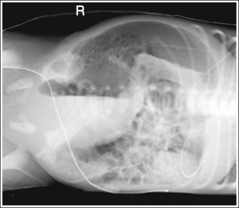
Image 74
• IR size and centering. With the neonate or infant positioned in a left lateral decubitus position, place an 8- × 10-inch (18- × 24-cm), lengthwise IR against the neonate or infant's posterior surface and position the abdomen in the middle of the IR. Center a horizontal central ray to the midsagittal plane at a transverse level 2 inches (5 cm) superior to the iliac crest. A larger IR and slightly inferior centering may be needed for larger infants. This IR and central ray placement centers the abdomen on the image, permitting tight collimation on all sides of the lungs. Open the longitudinal collimation to include the diaphragm (1 inch [2.5 cm]) inferior to the mammary line, and transversely collimate to within 0.5 inch (1.25 cm) of the lateral skin line.
• Gonadal shielding. Use gonadal shielding on all male abdominal images. Do not shield a female patient because the shield may obscure needed information.
Neonate and Infant AP (Lateral Decubitus) Abdomen Projection Analysis
The diaphragm is at the level of the eighth thoracic vertebra. The left posterior ribs are longer than the right, and the left iliac wing is wider than the right. The exposure was made after inspiration, and the patient was rotated toward the left side.
Correction
Take the exposure after the patient exhales or the manometer is at its lowest level, and rotate the patient toward the right side until the posterior ribs and the iliac wings are aligned perpendicular to the bed.
CHILD ABDOMEN: ANTEROPOSTERIOR PROJECTION (LEFT LATERAL DECUBITUS POSITION)
See Figures 3-75 and 3-76.
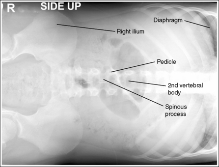
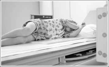
The analysis of the child AP (lateral decubitus) abdomen projection is the same as that of the infant or adult AP (lateral decubitus) abdomen projection (see earlier). The size of the child determines which criterion best meets the situation. For a discussion on topics needed to analyze Image 75, refer to the earlier discussion of adult or infant AP (lateral decubitus) abdomen projections.
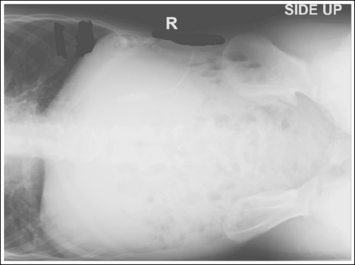
Image 75
Carroll, Q.B. Practical radiographic imaging, ed 8. Springfield, Ill: Charles C Thomas, 2007.
Hobbs, D.L. Chest radiography for radiologic technologists. Radiol Technol. 2007;78:494–516.
Jeffrey, B., Ralls, P., Leung, A., Brant-Zawadzke, M. Emergency imaging. Philadelphia: Lippincott Williams & Wilkins, 1999.