Hip and Pelvis
Hip: Anteroposterior Projection
Hip: Anteroposterior Oblique Projection (Modified Cleaves Method)
Hip: Axiolateral (Inferosuperior) Projection (Danelius-Miller Method)
Pelvis: Anteroposterior Projection
Pelvis: Anteroposterior Oblique Projection (Modified Cleaves Method)
Sacroiliac Joints: Anteroposterior Axial Projection
Sacroiliac Joints: Anteroposterior Oblique Projection (Left and Right Posterior Oblique Positions)
After completion of this chapter, you should be able to do the following:
• Identify the required anatomy on hip, pelvis, and sacroiliac joint projections.
• Describe how to properly position the patient, image receptor (IR), and central ray for hip, pelvic, and sacroiliac joint projections.
• State how to mark and display hip, pelvic, and sacroiliac joint images properly.
• List the requirements for accurate positioning for hip, pelvic, and sacroiliac joint projections and state how to properly reposition the patient when less than optimal projections are produced.
• List the soft tissue fat planes demonstrated on AP hip and pelvis projections, describe their locations, and discuss the importance of using a technique that adequately demonstrates them.
• Explain how leg rotation affects which anatomic structures of the proximal femur are demonstrated on AP hip and pelvis projections.
• Discuss why the leg of a patient with a proximal femoral fracture should never be rotated to obtain AP and lateral projections, and state how these projections should be taken.
• Define the differences demonstrated between the pelvic bones of female and those of male patients.
• Describe how the anatomic structures of the proximal femur are demonstrated differently for AP oblique hip and pelvis projections when the distal femur is elevated at different angles to the imaging table.
• Describe how the anatomic structures of the proximal femur are demonstrated differently for AP oblique hip and pelvis projections when the distal femur is abducted at different angles to the imaging table.
• Describe how to localize the femoral neck for an axiolateral hip projection.
• State which sacroiliac joint is of interest when the patient is rotated for AP oblique sacroiliac joint projections.
IMAGE ANALYSIS CRITERIA
The following image analysis criteria are used for all adult and pediatric hip and pelvis images and should be considered when completing the analysis for each hip and pelvis projection presented in this chapter (Box 7-1).
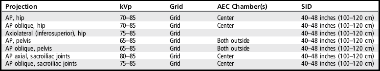
• Visibility of hip and pelvis details. An optimal kVp technique, as shown in Table 7-1, sufficiently penetrates the proximal femur, hip, and pelvic structures and provides a contrast scale necessary to visualize the pelvic and femoral details. Use a grid to absorb the scatter radiation produced by the proximal femur, hip, and pelvis, providing a higher contrast image. To obtain optimal density, set a manual milliampere-seconds (mAs) level based on the patient's part thickness or choose the appropriate automatic exposure control (AEC) chamber when recommended. AEC is contraindicated if the patient has hip or pelvic hardware or orthopedic apparatus.
HIP: ANTEROPOSTERIOR PROJECTION
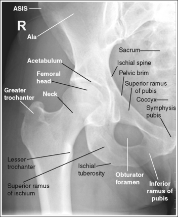
See Figure 7-1 and Box 7-2.
Contrast and density are adequate to demonstrate the pericapsular gluteal, iliopsoas, and obturator fat planes.
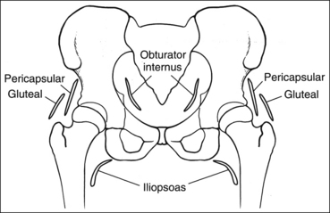
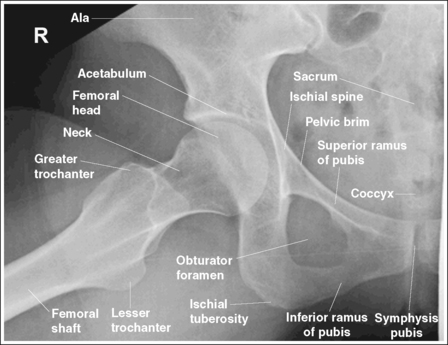
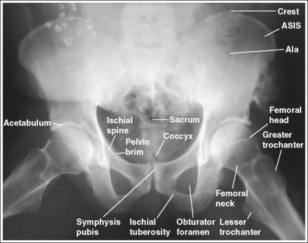
• Fat planes on AP hip and pelvic projections. When evaluating AP hip and pelvis projections, the reviewer not only analyzes the bony structures but also studies the placement of the soft tissue fat planes. Four fat planes are of interest on AP hip projections, and their visualization aids in the detection of intraarticular and periarticular disease: obturator internus fat plane, which lies within the pelvic inlet next to the medial brim; the iliopsoas fat plane, which lies medial to the lesser trochanter; the pericapsular fat plane, which is found superior to the femoral neck; and the gluteal fat plane, which lies superior to the pericapsular fat plane (Figure 7-2).
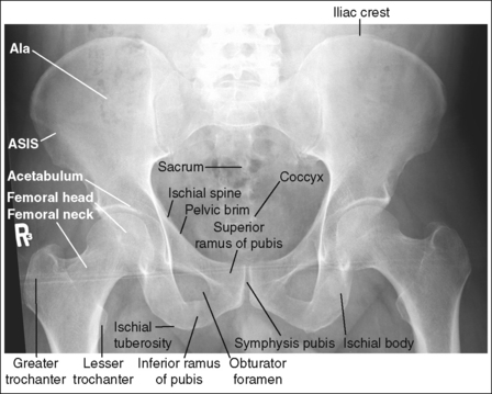
The pelvis demonstrates an AP projection. The ischial spine is aligned with the pelvic brim, the sacrum and coccyx are aligned with the symphysis pubis, and the obturator foramen is open.
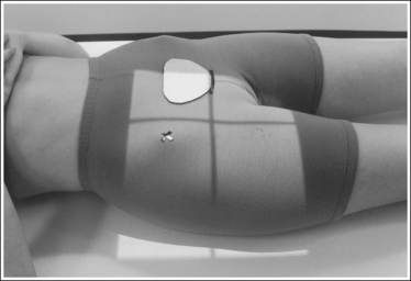
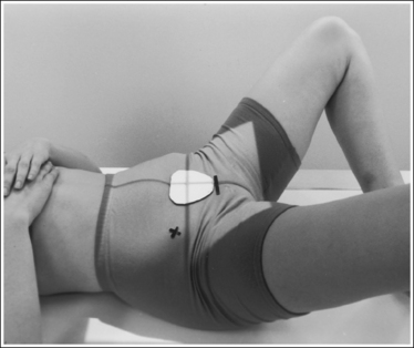
• An AP projection of the hip is obtained by placing the patient supine on the imaging table with the legs extended (Figure 7-3). To ensure that the pelvis is not rotated, judge the distances from the anterior superior iliac spines (ASISs) to the imaging table. The distances on each side should be equal.
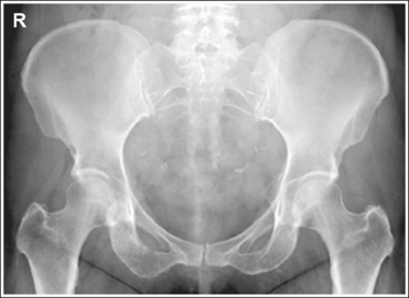
• Detecting pelvis rotation. Rotation on an AP hip projection is initially detected by evaluating the relationship of the ischial spine and the pelvic brim, the alignment of the sacrum and coccyx with the symphysis pubis, and the degree of obturator foramen demonstration. If the patient was rotated toward the affected hip, the ischial spine is demonstrated without pelvic brim superimposition, the sacrum and coccyx are not aligned with the symphysis pubis but are rotated away from the affected hip, and the obturator foramen is narrowed (see Image 1). If the patient has been rotated away from the affected hip, the ischial spine is not aligned with the pelvic brim but is demonstrated closer to the acetabulum, the sacrum and coccyx are not aligned with the symphysis pubis, but are rotated toward the affected hip, and the obturator foramen is widened (see Image 2).
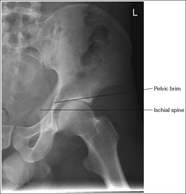
IMAGE 1
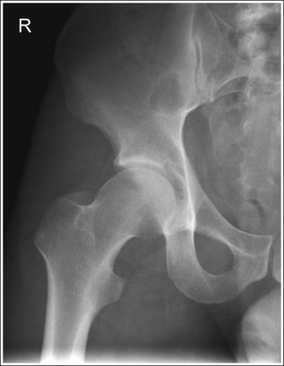
IMAGE 2
The femoral neck is demonstrated without foreshortening, the greater trochanter is in profile laterally, and the lesser trochanter is superimposed by the femoral neck.
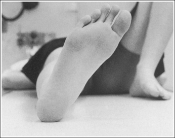
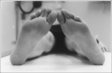
• Accurate leg positioning. To demonstrate an AP hip projection with the femoral neck shown without foreshortening and the greater trochanter in profile, the patient's leg should be internally rotated until the foot is angled 15 to 20 degrees from vertical and the femoral epicondyles are positioned parallel with the imaging table (Figure 7-4; see Figure 7-1). A sandbag or tape may be needed to help the patient maintain this internal leg rotation.
• Poor leg positioning. The relationship of the patient's leg to the imaging table determines how the femoral neck and trochanters are shown on an AP hip projection. In general, when patients are relaxed, their legs and feet are externally (laterally) rotated. On external rotation, the femoral neck declines posteriorly (toward the table) and is foreshortened on an AP hip projection. Increased external rotation increases the degree of posterior decline and foreshortening of the femoral neck on the image. If the patient's leg is externally (laterally) rotated enough to position the foot at a 45-degree angle and an imaginary line connecting the femoral epicondyles at a 60- to 65-degree angle with the imaging table, the femoral neck is demonstrated on end and the lesser trochanter is demonstrated in profile (Figure 7-5; see Image 3). If the patient's leg is positioned with the foot placed vertically and an imaginary line connecting the femoral epicondyles at approximately a 15- to 20-degree angle with the imaging table, the lesser trochanter is demonstrated in partial profile and the femoral neck is only partially foreshortened (see Image 4).
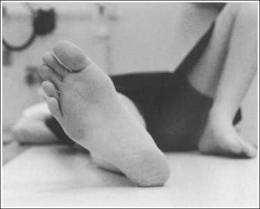
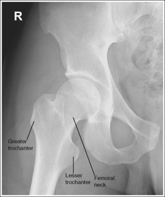
IMAGE 3
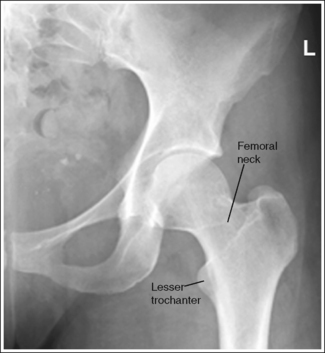
IMAGE 4
• Positioning for a fractured or dislocated proximal femur. When a patient has a dislocated or fractured proximal femur, the leg should not be internally rotated but left as is. Forced internal rotation of a dislocated or fractured proximal femur may injure the blood supply and nerves that surround the injured area. Because the patient's leg is not internally rotated when a fracture is suspected, the resulting AP hip projection may demonstrate the femoral neck with some degree of foreshortening and the lesser trochanter without femoral shaft superimposition (see Image 5).
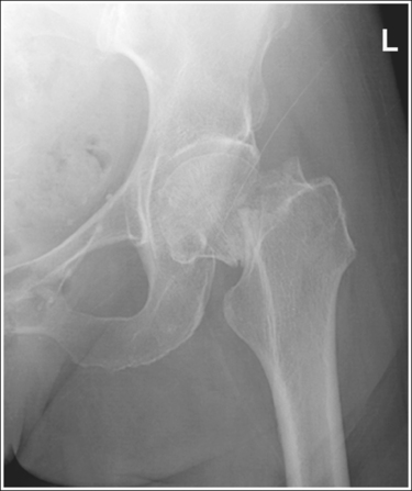
IMAGE 5
The femoral head or neck is at the center of the exposure field. The acetabulum, greater and lesser trochanters, femoral head and neck, and half of the sacrum, coccyx, and symphysis pubis are included within the collimated field. Any orthopedic apparatus located at the hip are included in their entirety.
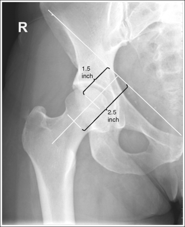
• A perpendicular central ray is centered 1.5 inches (4 cm) distal to the midpoint of a line connecting the ASIS and superior symphysis pubis, to center the hip joint in the center of the exposure field, and a perpendicular central ray is centered 2.5 inches (6.25 cm) distal to the midpoint of a line connecting the ASIS and superior symphysis pubis to place the femoral neck in the center of the exposure field (Figure 7-6). Center the IR to the central ray and open the longitudinal collimation enough to include the ASIS and any hip orthopedic apparatus. Transversely collimate to the patient's midsagittal plane and within 0.5 inch (1.25 cm) of the lateral hip skin line. Including half of the sacrum, coccyx, and symphysis pubis within the exposure field provides a way to evaluate pelvic rotation.
• A 10- × 12-inch (24- × 30-cm) IR placed lengthwise should be adequate to include all the required anatomic structures. A larger IR and lower centering point may be necessary to include hip orthopedic apparatus (Figure 7-7).
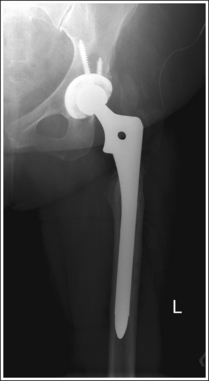
• Gonadal shielding. Use gonadal shielding on all male patients. Female patients should be shielded, although it is important that no pelvic anatomy be covered by the shield. It is not uncommon for patients with hip fractures to have an associated pelvic fracture. Remember that a shield placed on top of the patient will be greatly magnified.
Anteroposterior Hip Projection Analysis
The ischial spine is demonstrated without pelvic brim superimposition, the sacrum and coccyx are not aligned with the symphysis pubis but are rotated away from the affected hip, and the obturator foramen is narrowed. The patient was rotated toward the affected hip. The femoral neck is foreshortened, and the lesser trochanter is demonstrated in profile. The patient's leg was externally rotated.
Correction
Rotate the patient away from the affected hip until the ASISs are positioned at equal distances from the imaging table. Internally rotate the patient's leg until the foot is angled 15 to 20 degrees from vertical and the femoral epicondyles are positioned parallel with the imaging table, as shown in Figure 7-4.
Analysis
The ischial spine is not aligned with the pelvic brim but is demonstrated closer to the acetabulum, the sacrum and coccyx are not aligned with the symphysis pubis but are rotated toward the affected hip, and the obturator foramen is clearly demonstrated. The patient was rotated away from the affected hip (left posterior oblique [LPO] position).
Correction
Rotate the patient toward the affected hip until the ASISs are positioned at equal distances from the imaging table.
Analysis
The femoral neck is completely foreshortened, and the lesser trochanter is demonstrated in profile. The patient's leg was in external rotation with the foot positioned at a 45-degree angle and the femoral epicondyles at a 25- to 30-degree angle with the imaging table, as shown in Figure 7-5.
Correction
Internally rotate the patient's leg until the foot is angled 15 to 20 degrees from vertical and the femoral epicondyles are positioned parallel with the imaging table, as shown in Figure 7-4.
Analysis
The femoral neck is partially foreshortened, and the lesser trochanter is demonstrated in profile. The patient's leg was externally rotated, bringing the foot vertical and the femoral epicondyles to approximately a 15- to 20-degree angle with the imaging table.
Correction
Internally rotate the patient's leg until the foot is angled 15 to 20 degrees from vertical and the femoral epicondyles are positioned parallel with the imaging table, as shown in Figure 7-4.
HIP: ANTEROPOSTERIOR OBLIQUE PROJECTION (MODIFIED CLEAVES METHOD)
See Figure 7-8 and Box 7-3.
The pelvis demonstrates an AP projection. The ischial spine is aligned with the pelvic brim, the sacrum and coccyx are aligned with the symphysis pubis, and the obturator foramen is open.
• An AP oblique projection of the hip is obtained by placing the patient supine on the imaging table, with the unaffected leg extended and the affected leg flexed and abducted (Figure 7-9). To ensure that the pelvis is not rotated, judge the distances from the ASISs to the imaging table. The distance on each side should be equal.
• Detecting pelvis rotation. Rotation of the pelvis on an AP oblique projection is detected by evaluating the relationship of the ischial spine and the pelvic brim, the alignment of the sacrum and coccyx with the symphysis pubis, and the demonstration of the obturator foramen. If the patient was rotated toward the affected hip, the ischial spine is demonstrated without pelvic brim superimposition, the sacrum and coccyx are not aligned with the symphysis pubis but are rotated away from the affected hip, and demonstration of the obturator foramen is decreased (see Image 6). If the patient was rotated away from the affected hip, the ischial spine is not aligned with the pelvic brim but is demonstrated closer to the acetabulum, the sacrum and coccyx are not aligned with the symphysis pubis but are rotated toward the affected hip, and demonstration of the obturator foramen is increased (see Image 7).
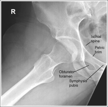
IMAGE 6
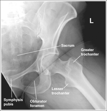
IMAGE 7
• Lauenstein and Hickey methods, lateral hip. The Lauenstein and Hickey methods are modifications of the AP oblique hip projection. For these methods, the patient is positioned as described for the AP oblique hip projection with the femur flexed and abducted, except that the pelvis is rotated toward the affected hip as needed to position the femur against the imaging table (Figure 7-10).
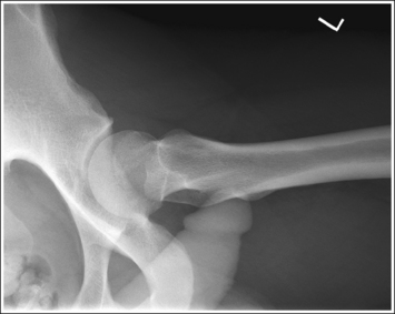
The lesser trochanter is in profile medially, and the femoral neck is superimposed over the greater trochanter.
• Accurate femur positioning. To position the greater trochanter accurately beneath the proximal femur and position the lesser trochanter in profile, flex the patient's knee and hip until the femur is angled at 60 to 70 degrees with the imaging table (20 to 30 degrees from vertical) (Figure 7-11).
• Effect of distal femur elevation on proximal femur visualization. For an AP oblique hip projection, the medial and lateral placement of the greater and lesser trochanters are determined when the patient flexes the knee and hip. Use a femoral skeletal bone for a better understanding of how the relationship of the greater and lesser trochanters to the proximal femur changes as the distal femur is elevated with knee and hip flexion. Begin by placing the femoral bone on a flat surface in an AP position. While slowly elevating the distal femur, observe how the greater trochanter rotates around the proximal femur. First, the greater trochanter moves beneath the proximal femur; then, as elevation of the distal femur continues, it moves from beneath the proximal femur and is demonstrated on the medial side of the femur.
• Poor distal femur elevation. If the knee and hip are not flexed enough to place the femur at this angle with the imaging table, the greater trochanter is demonstrated laterally, as it is on an AP projection (see Images 7 and 8). If the knee and hip are flexed too much, placing the femur at an angle greater than 60 to 70 degrees with the imaging table, the greater trochanter is demonstrated medially (see Image 9). The greater trochanter is also demonstrated medially, as shown in Image 9, when the foot and ankle of the affected leg are elevated and placed on top of the unaffected leg. This positioning causes the femur to rotate externally. The foot of the affected leg should remain resting on the imaging table.
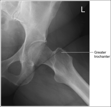
IMAGE 8
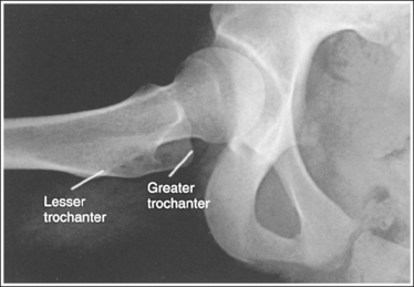
IMAGE 9
The femoral neck is partially foreshortened, and the proximal aspect of the greater trochanter is demonstrated at a transverse level halfway between the femoral head and the lesser trochanter.
• Accurate leg positioning. To demonstrate the femoral neck and proximal femur with only partial foreshortening and the proximal greater trochanter at a transverse level halfway between the femoral head and lesser trochanter on an AP oblique hip projection, abduct the femoral shaft to a 45-degree angle from vertical (Figure 7-12).
• Effect of leg abduction. The degree of femoral abduction determines the amount of femoral neck foreshortening and the transverse level at which the proximal greater trochanter is demonstrated between the femoral head and lesser trochanter.
Use a femoral skeleton bone to understand how leg abduction determines the visualization of the femoral neck and the position of the greater trochanter. Place the femoral bone on a flat surface in an AP position, with the distal femur elevated until the greater trochanter is positioned beneath the proximal femur and the lesser trochanter is in profile (20 to 30 degrees from vertical or 60 to 70 degrees from flat surface). From this position, abduct the femoral bone (move the lateral surface of the femoral bone toward the flat surface). As the bone moves toward the flat surface, observe how the femoral neck is positioned more on end and the greater trochanter moves proximally (toward the femoral head).
• Poor leg abduction. If the femoral shaft is abducted 20 to 30 degrees from vertical (60 to 70 degree angle with the imaging table; Figure 7-13) the femoral neck is demonstrated without foreshortening and the proximal greater trochanter is at the same transverse level as the lesser trochanter (see Image 10). If the femoral shaft is abducted to the imaging table (Figure 7-14), the proximal femoral shaft is demonstrated without foreshortening, the proximal greater trochanter is at the same transverse level as the femoral head, and the femoral neck is demonstrated on end (see Image 11).
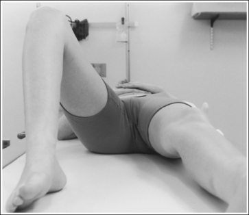
FIGURE 7-13 Femur in only slight abduction, 20 degrees from vertical (70 degrees from imaging table).
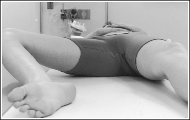
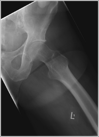
IMAGE 10
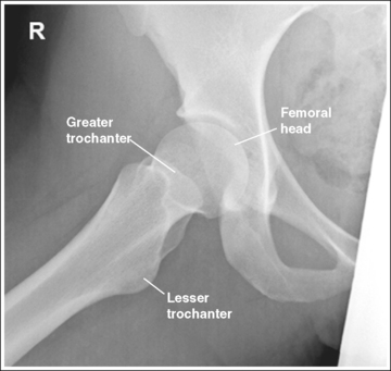
IMAGE 11
The femoral neck is at the center of the exposure field. The acetabulum, greater and lesser trochanters, and femoral head and neck, as well as half of the sacrum, coccyx, and symphysis pubis, are included within the collimated field.
• Center a perpendicular central ray 2.5 inches (6.25 cm) distal to the midpoint of a line connecting the ASIS and superior symphysis pubis to center the femoral neck in the center of the exposure field. Center the IR to the central ray and open longitudinal collimation to include the ASIS. Transversely collimate to the patient's midsagittal plane and transversely collimate to within 0.5 inch (1.25 cm) of the lateral hip skin line.
• Including half of the sacrum, coccyx, and symphysis pubis within the exposure field provides a way to evaluate pelvic rotation.
• A 10- × 12-inch (24- × 30-cm) IR placed lengthwise should be adequate to include all the required anatomic structures.
AP Oblique Hip Projection Analysis
The ischial spine is demonstrated without pelvic brim superimposition, the sacrum and coccyx are not aligned with the symphysis pubis but are rotated away from the affected hip, and the obturator foramen is not well demonstrated. The patient was rotated toward the affected hip.
Correction
Rotate the patient away from the affected hip until the ASISs are positioned at equal distances from the imaging table.
Analysis
The ischial spine is not aligned with the pelvic brim but is demonstrated closer to the acetabulum, the sacrum and coccyx are not aligned with the symphysis pubis but are rotated toward the affected hip, and the obturator foramen is well demonstrated. The greater trochanter is partially demonstrated laterally, indicating that the leg was flexed less than the needed 60 to 70 degrees from the imaging table. The patient was rotated away from the affected hip and the leg was not flexed enough.
Correction
Rotate the patient toward the affected hip until the ASISs are positioned at equal distances from the imaging table and increase the degree of knee and hip flexion until the femur is positioned at a 60- to 70-degree angle with the imaging table (see Figure 7-11).
Analysis
The greater trochanter is positioned laterally. The patient's knee was not flexed enough to align the femur at a 60- to 70-degree angle with the imaging table (20 to 30 degrees from vertical). The proximal greater trochanter is visible at about the same transverse level as the femoral head, indicating too much femur abduction.
Correction
Decrease the knee flexion until the femur is aligned at a 60- to 70-degree angle with the imaging table, as shown in Figure 7-11.
Analysis
The greater trochanter is positioned medially. The patient's knee was flexed more than needed, positioning the femur at an angle greater than 60 to 70 degrees with the imaging table (20 to 30 degrees from vertical).
Correction
Decrease the knee flexion until the femur is aligned at a 60- to 70-degree angle with the imaging table, as shown in Figure 7-11.
Analysis
The femoral neck is demonstrated without foreshortening, and the proximal greater trochanter and the lesser trochanters are demonstrated at approximately the same transverse level. The femur was in only slight abduction, at approximately a 70-degree angle with the imaging table (20 degrees from vertical), as shown in Figure 7-13.
Correction
If the proximal femoral shaft demonstrates too much foreshortening for your facility's standards, have the patient abduct the femur to a 45-degree angle with the imaging table.
Analysis
The femoral neck is demonstrated on end and is entirely foreshortened. The proximal greater trochanter is demonstrated on the same transverse level as the femoral head. The femur was abducted until it was positioned next to the imaging table, as shown in Figure 7-14.
Correction
Decrease the degree of femoral abduction until the femur is at a 45-degree angle with the imaging table, as shown in Figure 7-12.
HIP: AXIOLATERAL (INFEROSUPERIOR) PROJECTION (DANELIUS-MILLER METHOD)
See Figure 7-15 and Box 7-4.
Scatter radiation is controlled. The proximal femur demonstrates uniform density across it.
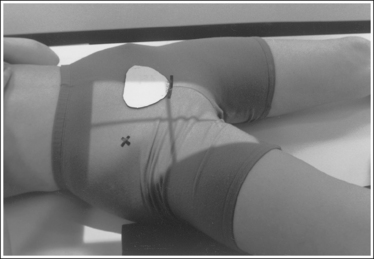
• Tight collimation and placement of a flat lead contact strip or the straight edge of a lead apron over the top, unused half of the IR, as shown in Figure 7-16, also prevent scatter radiation from reaching the IR.
• Compensating filter. Frequently, when an exposure (mAs) is set that adequately demonstrates the hip joint, the proximal femur is overexposed because of the difference in body thickness in these two regions. A wedge-type compensating filter attached to the x-ray tube can be used to obtain uniform image density of the hip joint and proximal femur. Align the thin end of the filter with the femoral neck and the thicker end with the proximal femur.
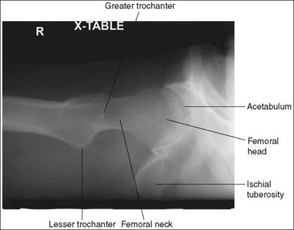
The femoral neck is demonstrated without foreshortening. The proximal aspects of the greater and lesser trochanters are demonstrated at approximately the same transverse level.
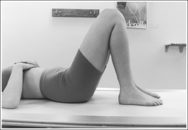
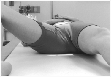
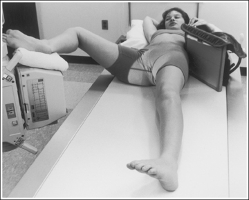
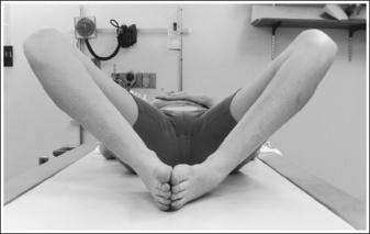
• An axiolateral projection of the hip is obtained by placing the patient on the imaging table in an AP projection, with the unaffected hip positioned next to the lateral edge of the table. Flex the patient's unaffected leg until the femur is as close to a vertical position as the patient can tolerate, and then abduct the leg as far as the patient will allow. Support this leg position by using a specially designed leg holder or suitable support. Flexion and abduction of the unaffected leg move its bony and soft tissue structures away from the affected hip. Inadequate flexion or abduction of the unaffected leg results in superimposition of soft tissue onto the affected hip, preventing visualization of the affected hip (see Image 12).
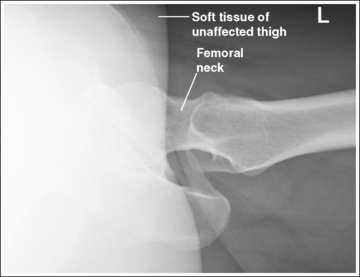
IMAGE 12
• IR placement. Once the patient's unaffected leg has been positioned, place the grid IR against the patient's affected side at the level of the iliac crest (Figure 7-16). To demonstrate the affected femoral neck without foreshortening, align the x-ray tube horizontally with the central ray perpendicular to the femoral neck and adjust the distal end of the IR until the receptor's long axis is perpendicular to the central ray and parallel with the femoral neck.
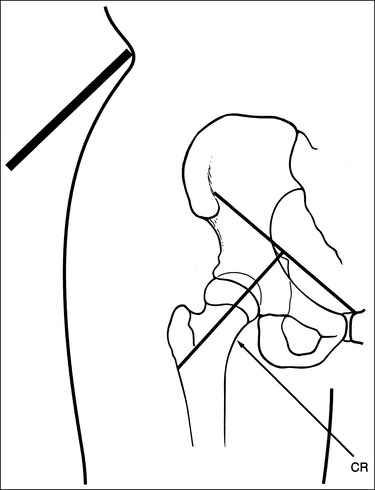
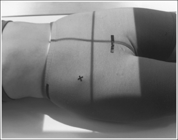
• Localizing the femoral neck for central ray alignment. To localize the affected femoral neck, first find the center of an imaginary line drawn between the superior symphysis pubis and the ASIS. Then, bisect that line by drawing a perpendicular line distally (Figure 7-17). This imaginary line parallels the long axis of the femoral neck as long as the leg is not abducted. Once the long axis of the femoral neck has been located, align the central ray perpendicular to it and the IR parallel with it.
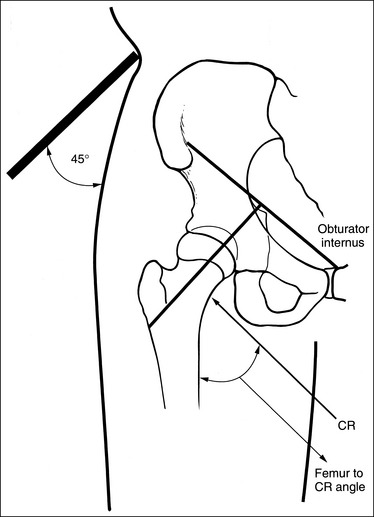
FIGURE 7-17 Locating the femoral neck and proper image receptor placement for small and average patients.
• Effect of central ray and femoral neck misalignment. Misalignment of the central ray with the femoral neck results in femoral neck foreshortening and a shift in the transverse level at which the greater trochanter is located. If the angle formed between the femur and the central ray is too large, the proximal greater trochanter is demonstrated proximal to the transverse level of the lesser trochanter and is superimposed by a portion of the femoral neck (see Image 13). If the angle between the femur and the central ray is too small, the proximal greater trochanter is demonstrated distal to the transverse level of the lesser trochanter. This mispositioning seldom occurs, because the imaging table and tube position prevent such a small angle.
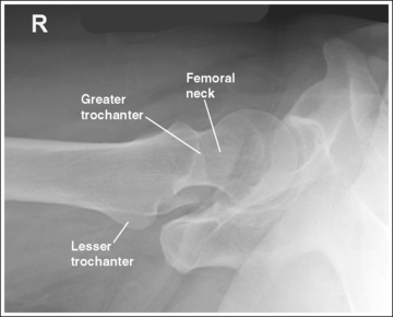
IMAGE 13
The lesser trochanter is in profile posteriorly, and the greater trochanter is superimposed by the femoral shaft.
• Rotation of the patient's affected leg determines the relationship of the lesser and greater trochanter to the proximal femur on an axiolateral hip projection. In general, when a patient is placed on the imaging table and the affected leg is allowed to rotate freely, it is laterally (externally) rotated.
• Effect of leg rotation on proximal femur visualization. To position the proximal femur in a lateral projection (90 degrees from the AP projection), demonstrating the lesser trochanter in profile posteriorly and superimposing the greater trochanter by the femoral shaft, the affected leg must be internally rotated until an imaginary line drawn between the femoral epicondyles is positioned parallel with the imaging table. The patient's foot is angled internally 15 to 20 degrees from a vertical position (Figure 7-18). If the affected leg is not rotated internally, the greater trochanter is demonstrated posteriorly and the lesser trochanter is superimposed over the femoral shaft (see Image 14). How much greater trochanter is demonstrated without femoral shaft superimposition depends on the degree of external rotation. Greater external rotation increases the amount of greater trochanter shown.
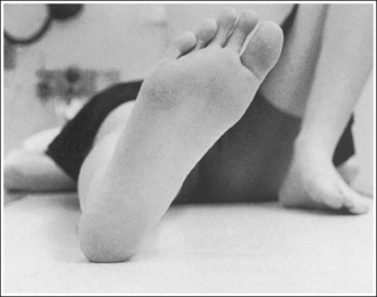
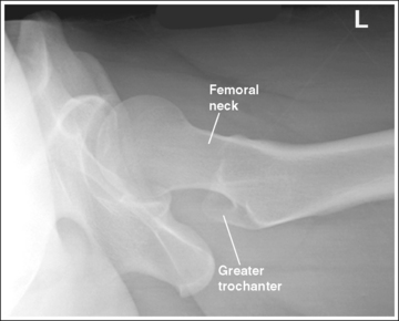
IMAGE 14
• Positioning for a proximal femoral fracture or dislocation. When a patient has a dislocated hip or a suspected or known proximal femoral fracture, the leg should not be internally rotated, but left as is. Forced internal rotation of a dislocated hip or fractured proximal femur may injure the blood supply and nerves that surround the injured area. Because the patient's leg is not internally rotated in such cases, it is acceptable for the greater trochanter to be demonstrated posteriorly and the lesser trochanter to be superimposed over the femoral shaft (see Image 15).
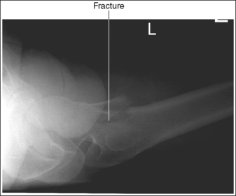
IMAGE 15
The femoral neck is at the center of the exposure field. The acetabulum, femoral head and neck, greater and lesser trochanters, and ischial tuberosity are included within the collimated field. Any orthopedic apparatus should be included in its entirety.
• Center a perpendicular central ray to the patient's midthigh, at the level of the femoral neck, to place it in the center of the exposure field. The center of the femoral neck is located at a level 2.5 inches (6.25 cm) distal to the midpoint of a line connecting the ASIS and superior symphysis pubis. Open the longitudinal collimation the full length of the IR. Transversely collimate to within 0.5 inch (1.25 cm) of the proximal femoral skin line.
• A 10- × 12-inch (24- × 30-cm) IR placed lengthwise should be adequate to include all the required anatomic structures. A larger IR and lower centering point may be necessary to include hip orthopedic apparatus (Figure 7-19).
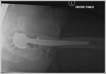
• IR placement alternative. The level at which the IR is placed along the patient's lateral body surface determines whether the acetabulum and femoral head are included on the IR. For patients with minimal lateral soft tissue thickness, the upper IR edge should be firmly placed in the crease formed at the patient's waist, just superior to the iliac crest (see Figure 7-17). For patients with ample lateral soft tissue thickness, the upper IR edge needs to be positioned superior to the iliac crest (Figure 7-20). This superior positioning will result in magnification because of the increase in the object–image receptor distance (OID) but is necessary if the acetabulum and femoral head are to be included on the axiolateral hip projection.
Axiolateral Hip Projection Analysis
Soft tissue from the unaffected thigh is superimposing the acetabulum and femoral head of the affected hip. The unaffected leg was not adequately flexed or abducted.
Correction
Flex and abduct the unaffected leg, drawing it away from the affected acetabulum and femoral head. If the patient is unable to adjust the unaffected leg further, the kVp and mAs can be increased to demonstrate this area. A wedge-type compensating filter may also be added to prevent overpenetration of the femoral neck and shaft.
Analysis
The proximal greater trochanter is demonstrated at a transverse level proximal to the lesser trochanter, and the femoral neck is partially foreshortened. The angle between the central ray and femur was too large.
Correction
Localize the femoral neck. Position the IR parallel with the femoral neck and the central ray perpendicular to the IR and femoral neck, as shown in Figure 7-17.
Analysis
The greater trochanter is demonstrated posteriorly, and the lesser trochanter is superimposed over the femoral shaft. The patient's affected leg was in external rotation.
Correction
Internally rotate the patient's leg until the femoral epicondyles are aligned parallel with the imaging table and the foot is angled internally 15 to 20 degrees from vertical, as shown in Figure 7-18.
PELVIS: ANTEROPOSTERIOR PROJECTION
See Figures 7-21 and 7-22 and Box 7-5.
• Regarding the male and female pelves. Be aware of the bony architectural differences that exist between the male and female pelves (Table 7-2). These differences are the result of the need for the female pelvis to accommodate fetal growth during pregnancy and fetal passage during delivery.
TABLE 7-2
Male and Female Pelvic Differences
| Parameter | Male | Female |
| Overall Shape | Bulkier, deeper, narrower | Smaller, shallower, and wider |
| Ala | Narrower, nonflared | Wider, flared |
| Pubic arch angle | Acute angle | Obtuse angle |
| Inlet shape | Smaller, heart shaped | Larger, rounded shape |
| Obturator foramen | Larger | Smaller |
Contrast and density are adequate to demonstrate the pericapsular gluteal, iliopsoas, and obturator fat planes of the pelvis.
• Refer to Figure 7-2 for an illustration of each fat plane location.
The pelvis demonstrates an AP projection. The ischial spines are aligned with the pelvic brim, the sacrum and coccyx are aligned with the symphysis pubis, and the ilia and obturator foramina are open and uniform in size and shape.
• An AP projection of the pelvis is accomplished by placing the patient supine on the imaging table, with the legs extended and the arms drawn away from the pelvic area (Figure 7-23). To ensure that the pelvis is not rotated, judge the distance from the ASIS to the imaging table on each side. The distances should be equal.
• Pelvic rotation. A nonrotated AP pelvis projection demonstrates symmetrical ilia and obturator foramina. Rotation is initially detected by evaluating the relationships of the ischial spines with the pelvic brim and of the sacrum and coccyx with the symphysis pubis. The ischial spines should be aligned with the pelvic brim, and the sacrum and coccyx should be in alignment with the symphysis pubis on a nonrotated pelvis. If the pelvis is rotated into a LPO position, the left ilium is wider than the right, the left obturator foramen is narrower than the right, the left ischial spine is demonstrated without pelvic brim superimposition, and the sacrum and coccyx are not aligned with the symphysis pubis but are rotated toward the right hip (see Image 16).
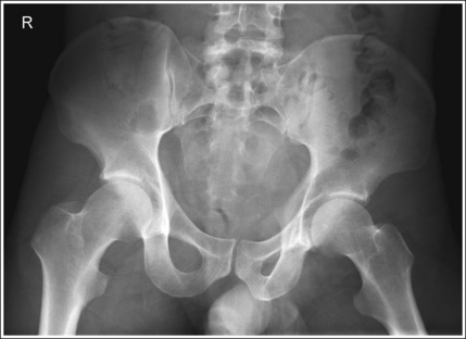
IMAGE 16
• If the patient was rotated into a right posterior oblique (RPO) position, the opposite is true. The right ilium is wider than the left, the right obturator foramen is narrower than the left, the right ischial spine is demonstrated without pelvic brim superimposition, and the sacrum and coccyx are rotated toward the left hip.
The femoral necks are demonstrated without foreshortening and the greater trochanters are in profile laterally, whereas the lesser trochanters are superimposed by the femoral necks.
• Accurate leg positioning. To demonstrate the femoral necks without foreshortening and the greater trochanters in profile on an AP pelvis projection, the patient's leg should be internally rotated until the feet are angled 15 to 20 degrees from vertical and the femoral epicondyles are positioned parallel with the imaging table (Figure 7-24; see Figure 7-21). Sandbags or tape may be needed to help maintain this internal leg rotation. An AP pelvis projection may not demonstrate the proximal femurs with exactly the same degree of internal rotation. How each proximal femur appears will depend on the degree of internal rotation placed on that leg.
• Poor leg positioning. The relationship of the patient's entire leg to the imaging table determines how the femoral necks and trochanters are shown on an AP pelvis projection. In general, when patients are relaxed, their legs and feet are externally (laterally) rotated. On external rotation, the femoral necks decline posteriorly (toward the table) and are foreshortened on an AP pelvis projection. Greater external rotation increases the posterior decline and foreshortening of the femoral necks. If the patient's legs are externally (laterally) rotated enough to position the feet at a 45-degree angle and an imaginary line connecting the femoral epicondyles at a 60- to 65-degree angle with the imaging table, the femoral necks are demonstrated on end and the lesser trochanters are demonstrated in profile (Figure 7-25; see Image 17). If the patient's legs are positioned with the feet placed vertically and an imaginary line connecting the femoral epicondyles at approximately a 15- to 20-degree angle with the imaging table, the lesser trochanter is demonstrated in partial profile and the femoral neck is only partially foreshortened (see Image 18).
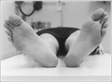
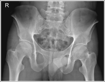
IMAGE 17
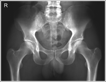
IMAGE 18
• Positioning for a proximal femoral fracture. Often, when a fracture of a proximal femur is suspected, an AP pelvis projection is ordered instead of an AP hip projection because pelvic fractures are frequently associated with proximal femur fractures. If a patient has a suspected fracture or a fractured proximal femur, the leg should not be internally rotated but should be left as is. Forced internal rotation of a fractured proximal femur may injure the blood supply and nerves that surround the injured area. Because the patient's leg is not internally rotated when a fracture is in question, such an AP pelvis projection demonstrates the affected femoral neck with some degree of foreshortening and the lesser trochanter without femoral shaft superimposition.
The inferior sacrum is at the center of the exposure field. The ilia, symphysis pubis, ischia, acetabula, femoral necks and heads, and greater and lesser trochanters are included within the collimated field.
• Center a perpendicular central ray to the midsagittal plane at a level halfway between the symphysis pubis and the midpoint of an imaginary line connecting the ASIS to place the inferior sacrum in the center of the exposure field. Center the IR to the central ray and open the longitudinal collimation the full 14-inch (35-cm) IR length for most adult patients. Transversely collimate to within 0.5 inch (1.25 cm) of the lateral skin line.
• A 14- × 17-inch (35- × 43-cm) IR placed crosswise should be adequate to include all the required anatomic structures.
• Central ray centering for analysis of hip joint mobility. When an AP pelvis projection is being taken specifically to evaluate hip joint mobility, the central ray should be centered to the midsagittal plane at a level 1 inch (2.5 cm) superior to the symphysis pubis. Such positioning centers the hip joints on the image but may result in clipping of the superior ilia.
Anteroposterior Pelvis Projection Analysis
The left obturator foramen is narrower than the right foramen, the left ischial spine is demonstrated without pelvic brim superimposition, and the sacrum and coccyx are rotated toward the right hip. The lesser trochanters are demonstrated medially and the femoral neck is foreshortened. The pelvis was rotated onto the left hip (LPO) and the legs were externally rotated.
Correction
Rotate the patient toward the right hip until the ASISs are positioned at equal distances from the imaging table and internally rotate the patient's legs until the feet are angled 15 to 20 degrees from vertical and the femoral epicondyles are positioned parallel with the imaging table, as shown in Figure 7-24.
Analysis
The femoral necks are completely foreshortened and the lesser trochanters are demonstrated in profile. The patient's legs were externally rotated, with the patient's feet at a 45-degree angle and the femoral epicondyles positioned at a 25- to 30-degree angle with the imaging table, as shown in Figure 7-25.
Correction
Internally rotate the patient's legs until the feet are angled 15 to 20 degrees from vertical and the femoral epicondyles are positioned parallel with the imaging table, as shown in Figure 7-24.
Analysis
The femoral necks are partially foreshortened, and the lesser trochanters are demonstrated in profile. The patient's legs were externally rotated, with the feet vertical and the femoral epicondyles at approximately a 15- to 20-degree angle with the imaging table.
Correction
Internally rotate the patient's legs until the feet are angled 15 to 20 degrees from vertical and the femoral epicondyles are positioned parallel with the imaging table, as shown in Figure 7-24.
PELVIS: ANTEROPOSTERIOR OBLIQUE PROJECTION (MODIFIED CLEAVES METHOD)
See Figure 7-26 and Box 7-6.
The pelvis demonstrates an AP projection. The ischial spines are aligned with the pelvic brim, the sacrum and coccyx are aligned with the symphysis pubis, and the ilia and obturator foramina are open and uniform in size and shape.
• An AP projection of the pelvis is accomplished by placing the patient on the imaging table with the legs flexed and abducted (Figure 7-27). To ensure that the pelvis is not rotated, judge the distance from the ASIS to the imaging table on each side. The distances should be equal.
• Detecting pelvic rotation. A nonrotated AP oblique pelvis projection will demonstrate symmetrical ilia and obturator foramina. Rotation can be detected by evaluating the relationships of the ischial spines with the pelvic brim and of the sacrum and coccyx with the symphysis pubis. The ischial spines should be aligned with the pelvic brim and the sacrum and coccyx should align with the symphysis pubis on a nonrotated pelvis. If the pelvis is rotated into an LPO position, the left ilium is wider than the right, the left obturator foramen is narrower than the right, the left ischial spine is demonstrated without pelvic brim superimposition, and the sacrum and coccyx are not aligned with the symphysis pubis but are rotated toward the right hip (see Image 19). If the patient is rotated into an RPO position, the opposite is true. The right ilium is wider than the left, the right obturator foramen is narrower than the left, the right ischial spine is demonstrated without pelvic brim superimposition, and the sacrum and coccyx are rotated toward the left hip.
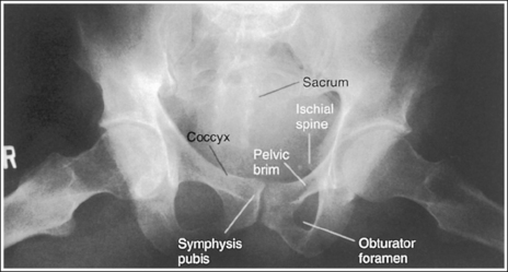
IMAGE 19
The lesser trochanters are in profile medially, and the femoral necks are superimposed over the adjacent greater trochanters.
• Accurate femur positioning. To position the greater trochanters beneath the proximal femurs accurately and position the lesser trochanters in profile, flex the patient's knees and hips until the femurs are angled 60 to 70 degrees with the imaging table (20 to 30 degrees from vertical; Figure 7-28).

• Poor distal femur elevation. For an AP oblique pelvis projection, the relationship of the greater and the lesser trochanters with the proximal femurs is determined when the patient flexes the knees and hips. If the knees and hips are not flexed enough to place the femur at a 60- to 70-degree angle with the imaging table, the greater trochanters are demonstrated laterally, as with an AP projection (see Image 20). If the knees and hips are flexed too much, placing the femurs at an angle greater than 60 to 70 degrees with the imaging table, the greater trochanters are demonstrated medially Image 9).
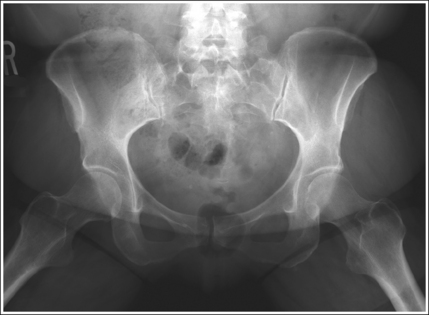
IMAGE 20
The femoral necks are partially foreshortened. The proximal aspects of the greater trochanters are demonstrated at a transverse level halfway between the femoral heads and lesser trochanters.
• Accurate leg positioning. To demonstrate the femoral necks and proximal femora with only partial foreshortening and the greater trochanters at a transverse level halfway between the femoral heads and lesser trochanters on an AP oblique pelvis projection, abduct the femoral shafts to a 45-degree angle from vertical (Figures 7-26 and 7-29).
• Effect of leg abduction. The degree of femoral abduction determines the amount of femoral neck foreshortening and the transverse level at which the greater trochanters are demonstrated between the femoral heads and lesser trochanters.
• Poor leg abduction. If the femoral shafts are abducted to 20 to 30 degrees from vertical (60- to 70-degree angle from the imaging table; Figure 7-30), the femoral necks are demonstrated without foreshortening and the proximal greater trochanters are at the same transverse level as the lesser trochanters on an AP oblique pelvis projection (see Image 21). If the femoral shafts are abducted until they are placed next to the imaging table (Figure 7-31), the proximal femoral shafts are demonstrated without foreshortening, the proximal greater trochanters are at the same transverse level as the femoral heads, and the femoral necks are demonstrated on end on an AP oblique pelvis projection (see Image 22).
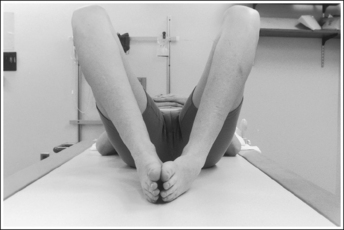
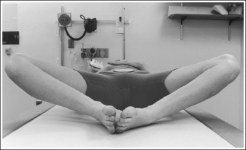
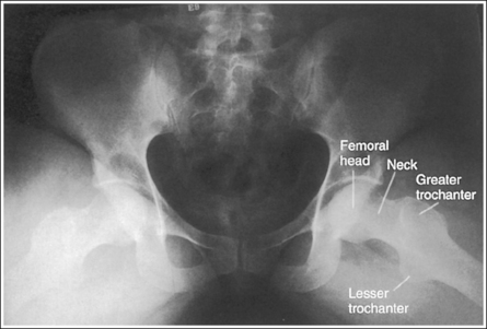
IMAGE 21
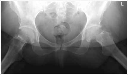
IMAGE 22
• Importance of symmetrical femoral abduction. An AP oblique pelvis projection may not demonstrate the proximal femurs with exactly the same degree of femoral abduction. How each proximal femur appears depends on the degree of femoral abduction placed on that leg. As a standard, unless the AP oblique pelvis projection is ordered to evaluate hip mobility, both femurs should be abducted equally for the image. This symmetrical abduction helps prevent pelvic rotation. It may be necessary to position an angled sponge beneath the patient's femurs to maintain the desired femoral abduction.
The inferior sacrum is at the center of the exposure field. The ilia, symphysis pubis, ischia, acetabula, femoral necks and heads, and greater and lesser trochanters are included within the collimated field.
• Center a perpendicular central ray to the midsagittal plane at a level 1 inch (2.5 cm) superior to the symphysis pubis. Center the IR to the central ray and open the longitudinal collimation the full 14-inch (35-cm) length for most adult patients. Transversely collimate to within 0.5 inch (1.25 cm) of the lateral skin line.
• A 14- × 17-inch (35- x 43-cm) IR placed crosswise should be adequate to include all the required anatomic structures.
Anteroposterior Oblique Pelvis Projection Analysis
The left obturator foramen is narrower than the right foramen, the left ischial spine is demonstrated without pelvic brim superimposition, and the sacrum and coccyx are rotated toward the right hip. The patient was rotated onto the left hip (LPO).
Correction
Rotate the patient toward the right hip until the ASISs are positioned at equal distances from the imaging table.
Analysis
The greater trochanters are partially demonstrated laterally, indicating that the leg was flexed less than the needed 60 to 70 degrees from the imaging table.
Correction
Increase the degree of knee and hip flexion until the femurs are positioned at a 60- to 70-degree angle with the imaging table.
Analysis
The femoral necks are demonstrated without foreshortening, and the proximal greater trochanter and lesser trochanter are demonstrated at approximately the same transverse level. The patient's femurs were in only slight abduction, at approximately a 70-degree angle with the imaging table (20 degrees from vertical), as shown in Figure 7-30.
Correction
Consult with reviewers in your facility to determine whether this is an acceptable image. If the proximal femoral shafts demonstrate too much foreshortening, have the patient abduct the femurs to a 45-degree angle with the imaging table.
Analysis
The femoral necks are demonstrated on end. The proximal greater trochanters are demonstrated on the same transverse level as the femoral heads. The patient's femurs were positioned next to the imaging table, as shown in Figure 7-31.
SACROILIAC JOINTS: ANTEROPOSTERIOR AXIAL PROJECTION
See Figure 7-32 and Box 7-7.
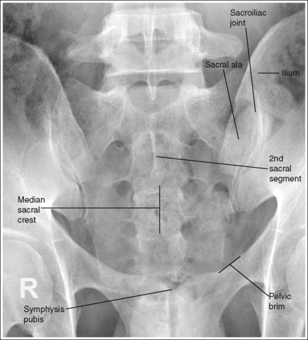
The sacroiliac joints are demonstrated in an AP axial projection. The median sacral crest is aligned with the symphysis pubis and the sacrum is at an equal distance from the lateral wall of the pelvic brim on both sides.
• An AP axial projection of the sacroiliac joints is obtained by positioning the patient supine on the imaging table with the legs extended. Position the patient's shoulders and ASISs at equal distances from the imaging table to prevent rotation (Figure 7-33).
• Detecting sacroiliac joint rotation. Rotation is detected on an AP axial sacroiliac joint projection by evaluating the alignment of the long axis of the median sacral crest with the symphysis pubis and the distance from the sacrum to the lateral pelvic brim. When the patient is rotated away from the supine position, the sacrum moves in a direction opposite from the movement of the symphysis pubis and is positioned next to the lateral pelvic brim situated farther from the imaging table. If the patient is rotated into an LPO position, the sacrum is rotated toward the patient's right pelvic brim. If the patient is rotated into an RPO position, the sacrum rotates toward the patient's left pelvic brim.
The sacroiliac joints are demonstrated without foreshortening and the sacrum is elongated, with the symphysis pubis superimposed over the inferior sacral segments.
• The patient is positioned supine, with the legs extended, and the lumbosacral curve causes the proximal sacrum and sacroiliac joints to be angled 30 to 35 degrees with the imaging table and IR. To demonstrate the sacroiliac joints without foreshortening, a 30-degree cephalic angle should be used for male patients and a 35-degree cephalic angle for female patients. Patients with less or greater lumbosacral curvature will require a decrease or increase, respectively, in cephalic angulation to maintain the 30- to 35-degree alignment of the central ray and sacroiliac joints. If an AP axial sacroiliac joint projection is taken with a perpendicular central ray or without enough cephalad angulation, the sacroiliac joints and the first through third sacral segments are foreshortened (see Image 23). If the AP axial sacroiliac joint projection is taken with too much cephalic angulation, the sacrum and sacroiliac joints demonstrate elongation and the symphysis pubis is superimposed over the inferior aspects of the sacrum and sacroiliac joints (see Image 24).
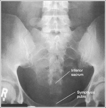
IMAGE 23
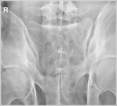
IMAGE 24
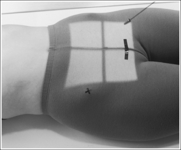
The long axis of the median sacral crest is aligned with the long axis of the exposure field.
• Aligning the long axis of the median sacral crest with the long axis of the exposure field allows for tight collimation and ensures that the central ray is angled directly into the sacroiliac joints. To obtain proper alignment, find the point halfway between the patient's palpable ASISs and then align this point and the palpable symphysis pubis with the center of the collimator's longitudinal light line.
The second sacral segment is at the center of the exposure field. The sacroiliac joints and the first through fourth sacral segments are included within the collimated field.
• Center the central ray to the patient's midsagittal plane at a level 1.5 inches (3 cm) superior to the symphysis pubis. Center the IR to the central ray, and open the longitudinal exposure field to the symphysis pubis. Transversely collimate to approximately a 9-inch (22-cm) collimated field size.
• A 10- × 12-inch (24- × 30-cm) IR placed lengthwise should be adequate to include all the required anatomic structures.
Anteroposterior Axial Sacroiliac Joint Projection Analysis
The sacroiliac joints are foreshortened, and the inferior sacrum is demonstrated without symphysis pubis superimposition. The central ray was inadequately angled.
SACROILIAC JOINTS: ANTEROPOSTERIOR OBLIQUE PROJECTION (LEFT AND RIGHT POSTERIOR OBLIQUE POSITIONS)
See Figure 7-34 and Box 7-8.
A right or left marker identifying the sacroiliac joint positioned farther from the IR is present on the image and is not superimposed over the anatomy of interest.
• Because the sacroiliac joint of interest is situated farther from the IR when AP oblique projections are taken, the marker used should identify the sacroiliac joint situated farther from the IR. This differs from the way most oblique projections are marked; routinely, the side marked is the one positioned closer to the IR.
The ilium and sacrum are demonstrated without superimposition, and the sacroiliac joint is open.
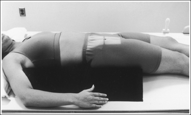
• An AP oblique sacroiliac joint projection is obtained by beginning with the patient positioned supine on the imaging table, with the legs extended. From this position, rotate the patient toward the unaffected side until the midcoronal plane is at a 25- to 30-degree angle with the imaging table and IR. The sacral ala and ilium are positioned in profile. Place a radiolucent support beneath the patient's elevated hip and thorax to help maintain the position (Figure 7-35). Both AP oblique projections (RPO and LPO positions) must be obtained to demonstrate the right and left sacroiliac joints. When AP oblique projections are taken, the elevated sacroiliac joint is the joint of interest.
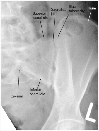
• Determining accuracy of obliquity. The accuracy of an AP oblique sacroiliac joint projection can be determined by the lack of ilium and sacral superimposition. The degree of separation or cavity demonstrated between the ilium and sacrum, which represents the sacroiliac joint, varies from patient to patient. The ilia and sacrum fit very snugly together and in older patients the joint spaces between them may be smaller or even nonexistent because of fibrous adhesions or synostosis. If the patient was not rotated enough to place the ilium and sacral ala in profile, the inferior and superior sacral aspects of the ala are demonstrated without ilium superimposition, whereas the lateral sacral ala is superimposed over the iliac tuberosity (see Image 25). The lateral sacrum is also demonstrated without ilium superimposition. If the patient was rotated more than needed to position the ilium and sacral ala in profile, the ilium is superimposed over the lateral sacral ala and the inferior sacrum (see Image 26).
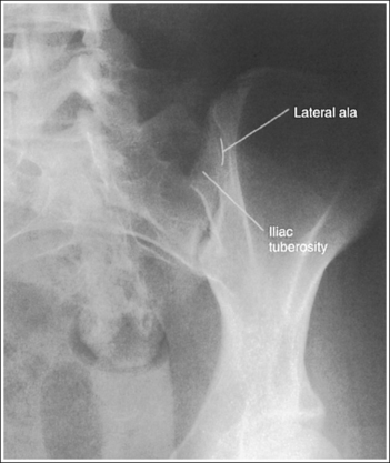
IMAGE 25
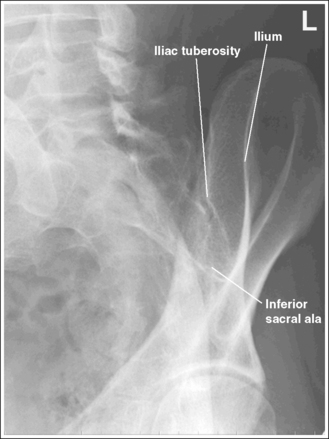
IMAGE 26
The long axis of the sacroiliac joint is aligned with the long axis of the exposure field.
• Aligning the long axis of the sacroiliac joint with the long axis of the exposure field allows for tight collimation without clipping any portion of the joint.
The sacroiliac joint of interest is at the center of the exposure field. The sacroiliac joint, sacral ala, and ilium are included within the collimated field.
• Center the central ray 1 inch (2.5 cm) medial to the elevated ASIS to position the sacroiliac joint of interest in the center of the exposure field. Center the IR to the central ray and open the longitudinal collimation to the elevated iliac crest. Transverse collimation should be to the elevated ASIS.
• A 10- × 12-inch (24- × 30-cm) IR placed lengthwise should be adequate to include all the required anatomic structures.
Anteroposterior Oblique Sacroiliac Joint Projection Analysis
The sacroiliac joint is closed. The superior and inferior sacral alae are demonstrated without iliac superimposition, and the lateral sacral ala is superimposed over the iliac tuberosity. The patient was not rotated enough.
Correction
Increase the pelvic obliquity. Because both the sacral ala and the ilium move simultaneously, the adjustment made should be only half the amount of superimposition of the sacral ala and iliac tuberosity.