Sternum and Ribs
Sternum: Posteroanterior Oblique Projection (Right Anterior Oblique Position)
Ribs: Anteroposterior or Posteroanterior Projection (Above or Below Diaphragm)
Ribs: Anteroposterior and Posteroanterior Projections Above Diaphragm
Ribs: Anteroposterior and Posteroanterior Projections Below Diaphragm
Ribs: Anteroposterior Oblique Projection (Right and Left Posterior Oblique Positions)
After completion of this chapter, you should be able to do the following:
• Identify the required anatomy on sternal and rib projections.
• Describe how to properly position the patient, image receptor (IR), and central ray on sternal and rib projections.
• State how to properly mark and display sternal and rib projections.
• List the image analysis requirements for sternal and rib projections with accurate positioning and state how to reposition the patient when less than optimal projections are produced.
• Describe how the patient is positioned to achieve homogeneous density on PA oblique sternal projections.
• Explain why a 30-inch (76 cm) source–image receptor distance (SID) is used on PA oblique sternal projections.
• Define costal breathing, and discuss the advantages of using it for PA oblique sternal projections.
• Describe how thoracic thickness affects how far the sternum is positioned from the vertebral column when the patient is rotated.
• List ways of reducing the amount of scatter radiation that reaches the IR when the sternum is imaged in the lateral projection.
• Discuss when it is appropriate to take an AP projection of the ribs rather than a PA projection and why the AP oblique projection is preferred over the PA oblique projection when the axillary ribs are imaged.
STERNUM
The following image analysis criteria are used for all adult and pediatric sternum and rib projections and should be considered when completing the analysis for each projection presented in this chapter (Box 10-1).
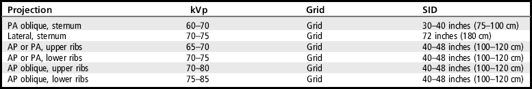
• Visibility of sternum and rib details. An optimal kVp technique, as shown in Table 10-1, sufficiently penetrates the sternal and rib structures and provides the contrast scale necessary to demonstrate the recorded details. To obtain optimal density, a milliampere seconds (mAs) level is set manually based on the patient's thoracic thickness.
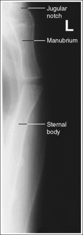
STERNUM: POSTEROANTERIOR OBLIQUE PROJECTION (RIGHT ANTERIOR OBLIQUE POSITION)
See Figure 10-1 and Box 10-2.
The sternum demonstrates homogeneous density.
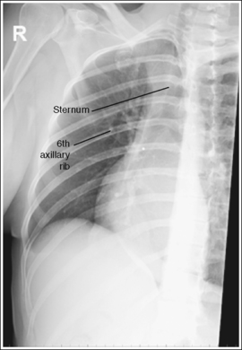
• Importance of choosing the right AP oblique projection (RAO position). The right AP oblique projection (RAO position) is used to rotate the sternum from beneath the thoracic vertebrae. It is chosen over the left anterior oblique (LAO) position because the RAO position superimposes the heart shadow over the sternum (see Image 1). Because the air-filled lungs and heart shadow have different densities, they demonstrate distinctly different degrees of density on an image produced using the same exposure factors. The air-filled lungs demonstrate greater image density than the heart shadow. Positioning the sternum in the heart shadow ensures homogeneous density across the entire sternum. Any portion of the sternum positioned outside the heart shadow demonstrates a darker density than the portion positioned within the heart shadow.
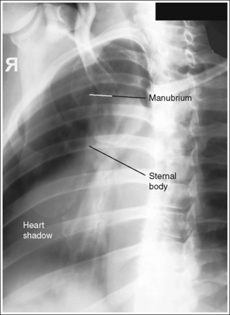
IMAGE 1
The sternum is demonstrated without motion or distortion. The ribs and lung markings are blurred, and the posterior ribs and left scapulae are magnified.
• In the PA oblique projection, the sternum has many overlying structures—the posterior ribs, lung markings, heart shadow, and left inferior scapula. Specific positioning techniques should be followed to show a sharply defined sternum while magnifying and blurring these overlying structures.
• Blurring overlying sternal structures. The SID recommended for the PA oblique sternum varies among positioning textbooks. It ranges from 30 inches (76 cm) to 40 inches (100 cm). A short (30-inch) SID provides increased magnification and blurring of the posterior ribs and left scapula but also results in a higher patient entrance skin dosage. Facility protocol dictates the SID. Using a breathing technique, which requires a long exposure time (3 to 4 seconds) and requires the patient to breathe shallowly (costal breathing) during the exposure, forces upward and outward and downward and inward movements of the ribs and lungs, thus blurring the posterior ribs and lung markings on the image. Deep breathing requires movement (elevation) of the sternum to provide deep lung expansion and should be avoided during breathing technique because this sternal motion would blur the sternum on the image (see Image 2).
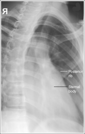
IMAGE 2
If breathing technique is not used, the details and cortical outlines of the posterior ribs, left scapula and lung markings are sharply defined, and the increased recorded detail obscures the details of the sternum (see Image 3).
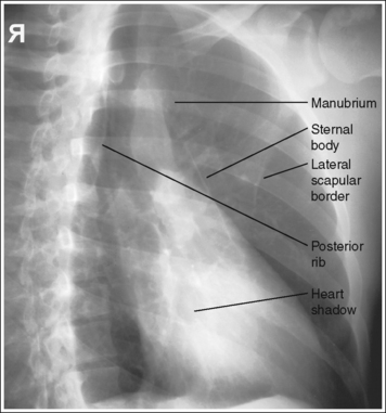
IMAGE 3
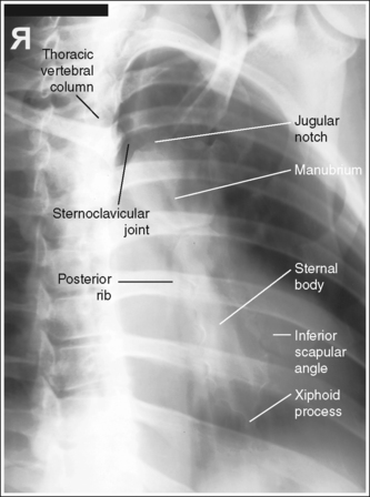
The manubrium, sternoclavicular (SC) joints, sternal body, and xiphoid process are demonstrated within the heart shadow without vertebral superimposition.
• Rotating the patient until the midcoronal plane is angled 15 to 20 degrees to the IR draws the sternum from beneath the thoracic vertebrae (Figure 10-2). This degree of obliquity provides you with a PA oblique projection of the sternum with only a small amount of rotation. To evaluate an anatomic structure sufficiently, two images of the area of interest, taken 90 degrees from each other, are obtained. The PA oblique (RAO) and lateral projections are obtained to fulfill this requirement for the sternum. Although these are not exactly 90 degrees from each other, it is necessary to rotate the patient slightly for the PA oblique projection to demonstrate the sternum without vertebral superimposition.
• Determining the required obliquity. To determine the exact obliquity needed to rotate the sternum away from the thoracic vertebral column on a prone patient, place the fingertips of one hand on the right SC joint and the fingertips of the other hand on the spinous processes of the upper thoracic vertebrae. Rotate the patient until your fingers on the SC joint are positioned just to the left of the fingers on the spinous processes.
• Evaluating accuracy of obliquity. When evaluating a PA oblique sternal projection, note that patient obliquity was sufficient when the sternum is located within the heart shadow and the manubrium and right SC joint are shown without vertebral superimposition. If the patient was not adequately rotated, the right SC joint and manubrium are positioned beneath the vertebral column (see Image 4). If patient obliquity was excessive, the sternum is rotated to the left of the heart shadow and the sternum demonstrates excessive transverse foreshortening (see Image 3).
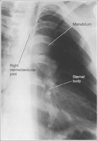
IMAGE 4
The midsternum is at the center of the exposure field. The jugular notch, SC joints, sternal body, and xiphoid process are included within the collimated field.
• To position the midsternum in the center of the exposure field, align the midsternum to the central ray and midline of the IR (approximately 3 inches to the left of the thoracic spinous processes), and then position the top of the IR approximately 1.5 inches (3.75 cm) superior to the jugular notch and center a perpendicular central ray to the IR.
• Determining IR size and collimation. The size of the IR and amount of collimation used for a PA oblique sternum projection depends on the age and gender of the patient. The adult male sternum is approximately 7 inches (18 cm) long, but the female sternum is considerably shorter. A 10- × 12-inch (24- × 30-cm) IR should sufficiently accommodate male and female adult patients. Because chest depth from the thoracic vertebrae to the manubrium is less than from the thoracic vertebrae to the xiphoid process, the manubrium remains closer to the thoracic vertebrae than the xiphoid process when the patient is rotated. The sternum, then, is not aligned with the longitudinal plane but is slightly tilted. Because of this sternal tilt, the transverse collimation should be confined to the thoracic spinous processes and the left inferior angle of the scapula.
Posteroanterior Oblique Sternum Projection Analysis
The patient was positioned in an LAO position. The thoracic vertebrae are superimposed over the heart shadow, and the sternum is demonstrated to the right of the heart shadow.
Analysis
The right SC joint is sharply defined, but the sternal body, posterior ribs, and lung markings are blurry. Breathing technique was used for this image, but the patient was breathing deeply instead of shallowly, causing the sternum to move and blur.
Analysis
The lung markings, posterior ribs, and left scapula are demonstrated without magnification or blurring, making it difficult to distinguish the sternum through these overlying structures. The SID was not shortened, and the patient's breathing was halted for this image. Also, patient obliquity was excessive, as indicated by the position of the sternum to the left of the heart shadow and by the amount of sternum rotation.
Correction
Shorten the SID to 30 inches (76 cm) if it is your facility's protocol, take the exposure while the patient is breathing shallowly, and decrease the degree of patient obliquity.
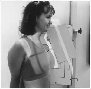
STERNUM: LATERAL PROJECTION
See Figure 10-3 and Box 10-3.
Sternum demonstrates homogeneous density.
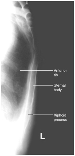
• Homogeneous density over the entire sternum region is difficult to obtain because the lower sternum is superimposed by the pectoral (chest) muscles or by the female breast tissue, whereas the upper sternum is free of this superimposition. The amount of density difference between the two halves of the sternum depends on the development of the patient's pectoral muscles and the amount of female breast tissue. Enlargement of either tissue requires an increase in exposure to obtain sufficient density to demonstrate the sternum through them. This increase may overexpose the upper sternum region on the image, requiring an additional image to be taken with a lower exposure so the entire sternum can be demonstrated (Figure 10-4).
• Reduce scatter radiation. A remarkable amount of scatter radiation is evident on a lateral sternal projection anterior to the sternum. One can be certain that if scatter is demonstrated here, it is also overlying the image of the sternum, decreasing the overall image contrast. To eliminate some of this scatter radiation and produce a higher contrast image, tightly collimate, use a grid, and place a lead sheet anterior to the sternum close to the patient's skin line (Figure 10-5). For the upright patient the lead sheet may be taped to the upright IR holder.
The sternum and chest demonstrate no rotation, the manubrium, sternal body, and xiphoid process are in profile, and the anterior ribs are not superimposed over the sternum.
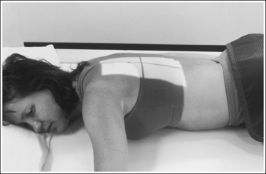
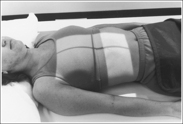
• To obtain a lateral sternum projection, place the patient in an upright position with the right or left lateral aspect of the body against the upright IR holder (see Figure 10-5). Avoid chest rotation by aligning the shoulders, posterior ribs, and posterior pelvic wings perpendicular to the IR. This alignment, which superimposes each of these posterior body parts on the image, is accomplished by resting your extended flat hand against each structure, individually, and then adjusting the patient's rotation until your hand is perpendicular to the IR. When the thorax is demonstrated without rotation, the sternum is in profile and the anterior ribs are superimposed over each other instead of over or under the sternum.
• Lateral sternal projection in supine position. If the patient is unable to be positioned upright, a lateral sternum projection can be obtained with the patient supine. In this position, rest the patient's arms against the sides, position a grid cassette vertically against the patient's arm, and use a horizontal beam. All other positioning and analysis requirements are the same as for an upright image.
• Detecting rotation and determining how to reposition the rotated patient. Rotation is effectively detected on a lateral sternum projection by evaluating the degree of anterior rib and sternal superimposition. If a lateral sternum projection demonstrates rotation, the right and left anterior ribs are not superimposed; one side is positioned anterior to the sternum and the other side is positioned posterior to the sternum.
Determine how to reposition after obtaining a rotated laternal sternal projection by using the heart shadow to identify the right and left anterior ribs. Because the heart shadow is located in the left chest cavity and extends anteroinferiorly, outlining the superior border of the heart shadow enables recognition of the left side of the chest. If the left lung and ribs were positioned anterior to the sternum, as shown in Figure 10-6, the outline of the superior heart shadow continues beyond the sternum and into the anteriorly located lung (see Image 5). If the right lung and ribs were positioned anterior to the sternum, as shown in Figure 10-7, the superior heart shadow does not continue into the anteriorly situated lung, but ends at the sternum (see Image 6). Once the right and left sides of the chest have been identified, reposition the patient by rotating the thorax. If the left lung and ribs were anteriorly positioned, rotate the left thorax posteriorly. If the right lung and ribs were anteriorly positioned, rotate the right thorax posteriorly.
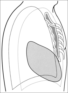
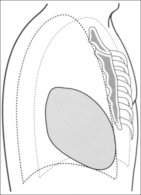
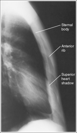
IMAGE 5
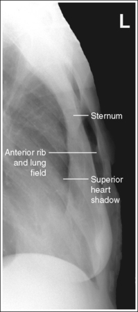
IMAGE 6
• Respiration. Elevation of the sternum, resulting from deep suspended inspiration, aids in better sternal demonstration by drawing the sternum away from the anterior ribs.
No superimposition of humeral soft tissue over the sternum is present.
• Extending the patient's arms behind the back with the hands clasped positions the humeral soft tissue away from the sternum.
The midsternum is at the center of the exposure field. The jugular notch, sternal body, and xiphoid process are included within the collimated field.
• To position the midsternum in the center of the exposure field, place the top edge of the IR 1.5 inches (4 cm) above the jugular notch, and then align the image receptor's long axis and a perpendicular central ray to the midsternum. Use the sternal skin surface when determining the location of the midsternum. Do not be thrown off by the vastness of the patient's pectoral muscles or breast tissue; these structures are situated anterior to the sternum and its skin surface.
• A 72-inch (180-cm) SID is used to minimize the sternal magnification that would result because of the long sternum to IR distance.
Lateral Sternum Projection Analysis
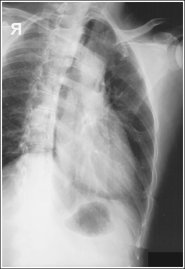
The anterior ribs are not superimposed, and the sternum is not in profile, indicating that the chest was rotated. The superior heart shadow extends anterior to the sternum and into the anteriorly situated lung, verifying it as the left lung. The patient was positioned with the left thorax rotated anteriorly and the right thorax rotated posteriorly.
Analysis
The anterior ribs are not superimposed and the sternum is not in profile, indicating that the chest was rotated. The superior heart shadow does not extend beyond the sternum, verifying that the right lung is situated anterior to the sternum and the left lung is situated posterior. The patient was positioned with the right thorax rotated anteriorly and the left thorax rotated posteriorly.
RIBS
• Soft tissue structures of interest. The demonstration of the soft tissue structures that surround the ribs is very important. When an upper rib fracture is suspected, the surrounding upper thorax, axillary, and neck soft tissues and vascular lung markings are carefully studied for signs (e.g., hematoma, presence of air) that indicate associated lung pathology (e.g., pneumothorax, interstitial emphysema) or rupture of the trachea, bronchus, or aorta. When a lower rib fracture is suspected, the upper abdominal tissue is examined for signs of associated injury to the kidney, liver, spleen, or diaphragm.
• A rib marker is present when requested by facility. Many facilities require that the technologist tape a rib marker (lead “BB”) on the patient's skin near the area where the ribs are tender. This aids the reviewer in pinpointing the exact location of potential injury.
RIBS: ANTEROPOSTERIOR OR POSTEROANTERIOR PROJECTION (ABOVE OR BELOW DIAPHRAGM)
See Figures 10-8 and 10-9 and Box 10-4.
Rib magnification is kept to a minimum.
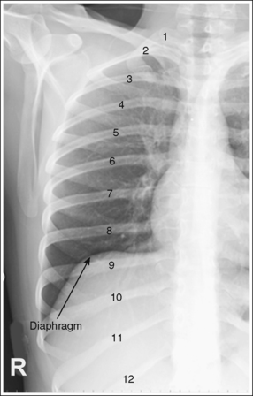
• AP versus PA projection. When the patient complains of anterior rib pain, obtain the image in a PA projection to place the anterior ribs closer to the IR. When the posterior ribs are the affected ribs, take the image in an AP projection to place the posterior ribs closer to the IR. Compare the difference in posterior rib detail sharpness in Figures 10-8 and 10-9. Figure 10-8 was obtained in an AP projection and Figure 10-9 in a PA projection. Note how the posterior ribs in Figure 10-9 are magnified, demonstrating less detail sharpness than the posterior ribs in Figure 10-8, which were positioned closer to the IR for the image.
The thorax demonstrates no rotation. The thoracic vertebrae–rib head articulations are demonstrated and the sternum and vertebral column are superimposed. The distances from the vertebral column to the sternal ends of the clavicles, when shown, are equal.
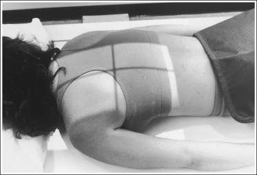
• Thoracic and rib rotation are avoided on the AP projection by flexing the patient's knees and placing the feet flat against the table. The shoulders should also be positioned at equal distances from the imaging table (Figure 10-10).
For the kyphotic patient, it may be necessary to place a sponge under each shoulder or obtain the image with the patient in an upright position to avoid rotation of the upper thorax. Preventing rotation in the PA projection is slightly more difficult. It is best accomplished by placing the patient's chin on a radiolucent sponge so that he or she can look straight ahead and still be able to breathe, as well as by positioning shoulders and anterosuperior iliac spines (ASISs) at equal distances from the table (Figure 10-11).
For the patient who has excessive abdominal tissue and has a tendency to roll to one side in the PA projection, it may be necessary to place a radiolucent sponge under the side of the lower abdomen toward which the patient is leaning or to obtain the image with the patient in an upright position to avoid thoracic rotation.
• Detecting rotation. Rotation is effectively detected on an AP or PA rib projection by evaluating the sternum and vertebral column superimposition and by comparing the distances between the vertebral column and the sternal ends of the clavicles. When an image of the ribs demonstrates rotation and the patient was in an AP projection, the side of the patient positioned closer to the IR demonstrates the sternum and SC joint without vertebral column superimposition (see Image 7). The opposite is true for a PA projection—the side of the chest positioned farther from the IR demonstrates the sternum and the SC joint without vertebral column superimposition (see Image 8).
• Rotation versus scoliosis. In images of patients with spinal scoliosis, the ribs and vertebral column will appear rotated because of the lateral deviation of the vertebrae (see Image 9). Become familiar with this condition to prevent unnecessarily repeated procedures on these patients.
RIBS: ANTEROPOSTERIOR AND POSTEROANTERIOR PROJECTIONS ABOVE DIAPHRAGM
The scapulae are located outside the lung field, and the chin does not obscure the superior ribs.
• For the AP projection, position the scapulae outside the lung field by placing the back of the patient's hands on the hips or under the patient's head and rotating the elbows and shoulders anteriorly.
• For the PA projection, position the scapulae outside the lung field by abducting and internally rotating the patient's arms, forcing the shoulders to rotate anteriorly.
• To avoid rotation, it is best to position the two arms in the same manner, even when only one side of the thorax is being imaged. If the scapula is not drawn away from the lung field, it is demonstrated in the upper ribs (see Image 10).
• Elevate the chin to position it superior to the upper ribs.
Nine posterior ribs are demonstrated above the diaphragm, indicating full lung aeration.
• The number of ribs demonstrated above the diaphragm is determined by the depth of patient inspiration. In full inspiration, when the patient is recumbent, approximately nine posterior ribs are demonstrated above the diaphragm. When the patient is in an upright position, 10 or 11 posterior ribs will be demonstrated. If the patient does not fully inhale, the inferior ribs are demonstrated below the diaphragm. Any ribs situated below the diaphragm are not well demonstrated because an increase in exposure would be needed to penetrate the abdominal tissue they surround. To maximize the number of ribs located above the diaphragm, the exposure should be taken with the patient in full inspiration.
The seventh posterior rib is at the center of the exposure field. The affected side's first through ninth ribs and the vertebral column are included within the collimated field.
• In the AP projection, to place the seventh posterior rib at the center of the exposure field, center a perpendicular central ray halfway between the midsagittal plane and the affected lateral rib surface at a level halfway between the jugular notch and the xiphoid process.
• In the PA projection, center a perpendicular central ray halfway between the midsagittal plane and the affected lateral rib surface at the level of the inferior scapular angle. Palpate the scapular angle with the arm next to the patient's body. After accurate centering has been accomplished, abduct the arm to position it out of the collimated field. Abducting the arm shifts the inferior scapular angle laterally and inferiorly, so centering should be accomplished before arm abduction.
• Once the central ray is centered, collimate transversely to the thoracic vertebral column and the patient's lateral skin line. Because above-diaphragm ribs are imaged on inspiration, causing the thorax to expand transversely, perform the transverse collimation with the patient in deep inspiration. Open the longitudinal collimation the full 17-inch (43-cm) IR length.
• A 14- × 17-inch (35- × 43-cm) IR placed lengthwise should be adequate to include all the required anatomic structures.
• Alternative IR size and centering method when both sides of the ribs are on the same image. It should be noted that some positioning textbooks suggest that PA or AP above- and below-diaphragm rib images be taken to include both sides of the ribs on the same image. For this positioning, the IR is positioned crosswise and centering is to the midsagittal plane instead of halfway between the midsagittal plane and lateral rib surface.
RIBS: ANTEROPOSTERIOR AND POSTEROANTERIOR PROJECTIONS BELOW DIAPHRAGM
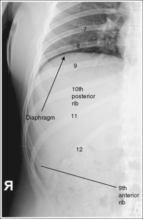
The eighth through twelfth posterior ribs are demonstrated below the diaphragm.
• The number of ribs demonstrated below the diaphragm is determined by the depth of patient inspiration. In full inspiration, up to 10 posterior ribs may be demonstrated above the diaphragm (see Image 11). To maximize demonstration of the lower ribs the exposure should be obtained on expiration. In expiration, only seven or eight posterior ribs are clearly visible above the diaphragm, and four or five ribs are demonstrated below the diaphragm. When below-diaphragm ribs are imaged, it is necessary to use a higher kVp and exposure than needed for above-diaphragm ribs to penetrate the denser abdominal tissue. Any ribs situated above the diaphragm for this image may be too dark to evaluate.
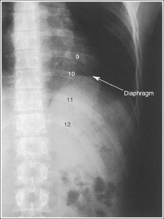
The tenth posterior rib is at the center of the exposure field. A portion of the thoracic and lumbar vertebral column and the eighth through twelfth ribs of the affected side of the patient are included within the collimated field.
• To center the tenth posterior rib in the center of the field and include the eighth through twelfth ribs on the AP and PA below-diaphragm rib projections, place the lower edge of the IR at the level of the iliac crest and center the image receptor's long axis halfway between the midsagittal plane and the affected lateral rib surface. Center a perpendicular central ray to the IR.
• For a hypersthenic patient with a short wide thorax, the centering needs to be positioned slightly higher. Place the lower border of the IR approximately 2 inches (5 cm) above the iliac crest.
• Transversely collimate to the vertebral column and the patient's lateral skin line. Open the longitudinal collimation the full 17-inch (43-cm) field size.
• A 14- × 17-inch (35- × 43-cm) IR placed lengthwise should be adequate to include all the anatomic structures.
Anteroposterior or Posteroanterior Rib Projection Analysis
The sternum is demonstrated to the right of the patient's vertebral column. The patient was rotated. In an AP projection, the sternum is rotated toward the side that was positioned closer to the IR. For this image, the patient was rotated toward the right side.
Correction
Position the patient in an AP projection by flexing his or her knees and placing his or her shoulders at equal distances from the imaging table.
Analysis
The sternum and the SC joints are demonstrated to the left of the patient's vertebral column. The patient was rotated. In a PA projection the sternum and SC joints are rotated toward the side that was positioned farther from the IR. For this image, the patient was rolled toward the right side, away from the left side.
Correction
Position the patient in a PA projection by having the patient look straight ahead, with the chin elevated on a sponge. The shoulders and ASISs should be positioned at equal distances from the imaging table.
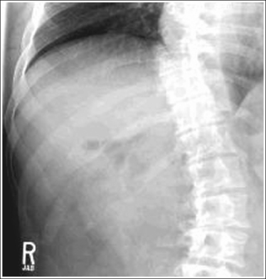
Analysis
The distances from the vertebral column to the lateral rib edges down the length of the thoracic region vary, indicating that the patient has spinal scoliosis.
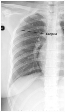
Analysis
The left scapula is superimposed over the upper lateral rib field. The left elbow and shoulder were not rotated anteriorly.
Correction
If the patient's condition allows, place the back of the patient's hands on the hips, and rotate the elbows and shoulders anteriorly.
RIBS: ANTEROPOSTERIOR OBLIQUE PROJECTION (RIGHT AND LEFT POSTERIOR OBLIQUE POSITIONS)
See Figure 10-12 and Box 10-5.
Rib magnification is kept to a minimum.
• AP oblique versus PA oblique projections. Oblique ribs may be performed using AP and PA oblique projections but, to provide maximum axillary rib detail, the AP oblique projection (right posterior oblique [RPO] and left posterior oblique [LPO] positions) should be routinely performed. In the AP oblique projection (Figure 10-13), the axillary ribs are placed closer to the IR than in the PA oblique projection (see Image 12), resulting in less rib magnification and greater recorded detail.
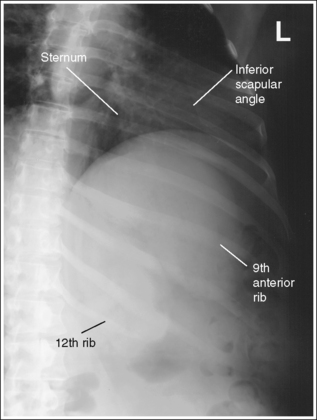
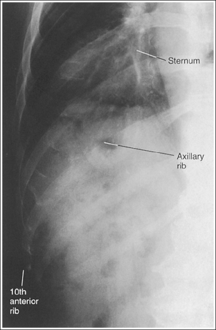
IMAGE 12
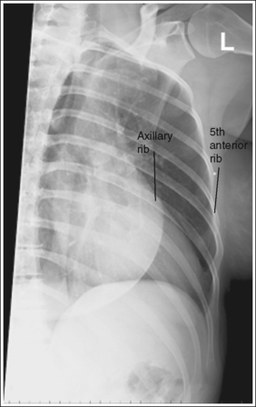
The thorax has been rotated 45 degrees. The inferior sternal body is located halfway between the lateral rib surface and the vertebral column, and the axillary ribs are seen without foreshortening. The axillary ribs are demonstrated without superimposition and are located in the center of the collimated field, and the anterior ribs are located at the lateral edge.
• To open up the curvature of the axillary ribs, rotate the patient toward the affected side until the midcoronal plane is angled 45 degrees with the IR, placing the axillary ribs parallel with the IR (Figures 10-14 and 10-15). If the patient is rotated in the opposite direction, the axillary ribs demonstrate increased foreshortening (see Image 13).
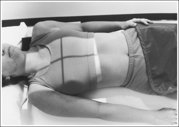
FIGURE 10-14 Proper patient positioning for AP oblique above-diaphragm rib projection (RPO position).
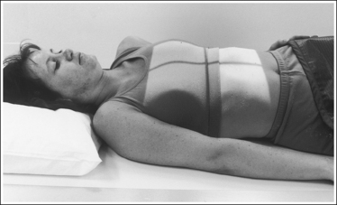
FIGURE 10-15 Proper patient positioning for AP oblique below-diaphragm rib projection (RPO position).
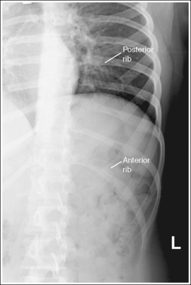
IMAGE 13
• Determining accuracy of rotation. Because the sternum rotates toward the affected axillary ribs on thoracic rotation, the position of the sternum can be used to identify the accuracy of patient rotation. If the inferior sternum is positioned halfway between the vertebral column and the anterior ribs, the patient was rotated 45 degrees and the axillary ribs are “opened.” When the desired 45-degree obliquity has not been obtained, view the position of the inferior sternum to determine how to reposition the patient. If the sternal body is demonstrated next to the vertebral column, the patient was insufficiently rotated (see Image 14). If the inferior sternal body is demonstrated laterally, the patient was rotated more than 45 degrees.
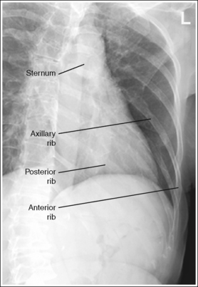
IMAGE 14
RIBS: ABOVE DIAPHRAGM
Ten axillary ribs are demonstrated above the diaphragm, indicating full lung aeration.
• The number of ribs demonstrated above the diaphragm is determined by the depth of patient inspiration. In full inspiration, when the patient is recumbent, 10 axillary ribs are usually demonstrated above the diaphragm. When the patient is in an upright position, 10 or 11 axillary ribs are demonstrated. If the patient does not fully inhale, the inferior axillary ribs are positioned below the diaphragm. Any ribs situated below the diaphragm are not well demonstrated because an increase in exposure would be needed to penetrate the abdominal tissue they surround. To maximize the number of ribs located above the diaphragm, take the exposure with the patient in full inspiration.
The seventh axillary rib is at the center of the exposure field. The first through tenth axillary ribs of the affected side and thoracic vertebral column are included within the collimated field.
• For the above-diaphragm AP oblique axillary rib projections (RPO or LPO positions), the seventh posterior rib is placed at the center of the image by centering a perpendicular central ray halfway between the midsagittal plane and the affected lateral rib surface at a level halfway between the jugular notch and the xiphoid process.
• Once the central ray is centered, collimate transversely to the thoracic vertebral column and the patient's lateral skin line. Because above-diaphragm ribs are imaged on inspiration, causing the thorax to expand transversely, perform the transverse collimation with the patient in deep inspiration. Open the longitudinal collimation the full 17-inch (43-cm) IR length.
• A 14- × 17-inch (35- × 43-cm) IR placed lengthwise should be adequate to include all the required anatomic structures.
RIBS: BELOW DIAPHRAGM
The ninth through twelfth axillary ribs are demonstrated below the diaphragm.
• The number of ribs located below the diaphragm is determined by the depth of patient inspiration. In full suspended inspiration, up to 10 axillary ribs may be demonstrated above the diaphragm. In expiration, only seven or eight axillary ribs are clearly visible above the diaphragm, and four or five ribs are demonstrated below the diaphragm. When below-diaphragm ribs are imaged, it is necessary to use a higher kVp and exposure than needed for the above-diaphragm ribs to penetrate the denser abdominal tissue. Any ribs situated above the diaphragm for this image may be too dark to evaluate. To maximize the number of ribs located below the diaphragm, take the exposure on full suspended expiration.
The tenth axillary rib is at the center of the exposure field. A portion of the thoracic and lumbar vertebral column and the eighth through twelfth axillary ribs of the affected side of the patient are included within the collimated field.
• To place the tenth axillary rib in the center of the exposure field for below-diaphragm AP oblique axillary rib projections, place the lower edge of the IR at the level of the iliac crest and center the image receptor's long axis halfway between the midsagittal plane and the affected lateral rib surface. Center a perpendicular central ray to the IR.
For a hypersthenic patient with a short wide thorax, the centering needs to be positioned slightly higher. Place the lower border of the IR approximately 2 inches (5 cm) above the iliac crest.
• Transversely collimate to the vertebral column and the patient's lateral skin line. Open the longitudinal collimation the full 17-inch (43-cm) field size.
• A 14- × 17-inch (35- × 43-cm) IR placed lengthwise should be adequate to include all the anatomic structures.
Anteroposterior Oblique Rib Projection Analysis
This is a PA oblique projection of the lower ribs. The sternum demonstrates sharply defined cortical outlines, but the axillary ribs are magnified and demonstrate little definition.
Correction
The axillary ribs would demonstrate greater definition if an AP oblique projection had been taken instead. Replace an RAO position with an LPO position to demonstrate the left axillary ribs. Replace an LAO position with an RPO position to demonstrate the right axillary ribs.
Analysis
The axillary ribs demonstrate increased foreshortening and the sternum is rotated away from the affected ribs. The patient was rotated in the wrong direction.
Correction
For AP oblique projections, rotate the patient toward the affected side. For PA oblique projections, rotate the patient away from the affected side.