Chapter 7 Resolution
Resolution is a term which describes the ability of an imaging system to differentiate between structures, images, or events and display them as separate entities.
In this chapter we are going to examine the following categories of resolution and the factors that influence them:
SPATIAL RESOLUTION
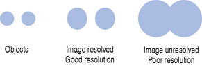
This is the ability to display two structures situated close together as separate images. When the structures are displayed as separate images we say that they are resolved (see Fig. 7.1).
In ultrasound imaging the spatial resolution depends ultimately on the wavelength of the sound used to produce the image. For example, the wavelength of a 5 MHz ultrasound beam is approximately 0.3 mm so it would not be possible to resolve objects less than 0.3 mm apart using a 5 MHz transducer.
In ultrasound imaging, spatial resolution is divided into two components:
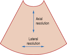
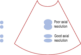
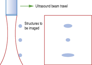
Axial Resolution
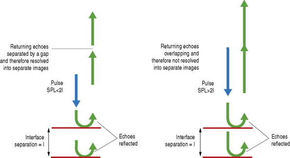
This is resolution along the axis of the beam and depends upon the spatial pulse length – a short pulse length gives good axial resolution and the best resolution that can be achieved is half the spatial pulse length. For example if the pulse length is 1 mm then structures situated along the axis, which are less than 0.5 mm apart, will not be resolved (see Figs 7.3 and 7.4).
Factors affecting spatial pulse length and therefore axial resolution
Frequency Each pulse of ultrasound is approximately two wavelengths long and therefore a shorter wavelength will reduce the pulse length. The wavelength of ultrasound depends on its frequency with the higher frequency waves having the shorter wavelengths. Therefore using ultrasound with a higher frequency for imaging will result in a shorter spatial pulse length and improved axial resolution.
Transducer design The pulse length depends upon the amount of damping applied to the piezoelectric crystal. The damping material is used to reduce ‘ringing’; this is where the crystal continues to oscillate and produce sound after the driving voltage has ceased. Increasing the amount of damping makes the pulse length shorter and therefore improves the axial resolution.
Field of view (FOV)
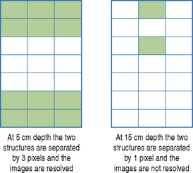
Axial resolution may be affected by the FOV. In order for images of two structures to be resolved on the monitor screen they must be separated by at least 2 pixels, but as the FOV increases the distance represented by 2 pixels also increases. Therefore if the distance between the images of two structures is less than 2 pixels they will not be resolved.
The consequence of the above is that using a large FOV may be detrimental to the axial resolution (see Fig. 7.5).
Lateral Resolution
This is resolution at right angles to the beam and depends upon the beam width – a narrow beam width gives good spatial resolution and the best resolution that can be achieved is equal to the beam width at the focus of the beam (see Fig. 7.6).
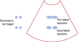
The lateral resolution for a particular ultrasound machine is generally not as good as the axial resolution.
The beam width determines the size of the echoes displayed on the screen and structures must be separated by a distance greater than the beam width for them to be resolved into separate images (see Fig. 7.7).
Structures will only be resolved into separate images if the separation between them is greater than the size of the beam width – the beam must fit into the gap between the two structures so that it can return ‘no echoes’ from that position (see Fig. 7.8).
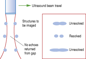
Fig. 7.8 How structures must be separated by the beam width in order to be resolved into separate images
Factors affecting beam width and therefore lateral resolution
Diameter of the piezoelectric crystal (aperture)
As the aperture increases the beam width close to the crystal face increases.
Transducer frequency Higher frequency beams have a longer near field and less divergent far field so the beam width is narrower than a lower frequency beam in these regions.
Focusing The degree of focusing, the length of the focal zone, and the number of focal zones all affect beam width.
Distance from the crystal (where lateral resolution is measured) The best lateral resolution is found at the focal point of the beam. The beam width increases the further it is from the focal point.
CONTRAST RESOLUTION
Contrast resolution is the ability of the imaging system to differentiate between body tissues and display them as different shades of gray. The main factors affecting it are as follows:
Transducer design Higher frequency transducers, which have a smaller slice thickness, generally provide better contrast resolution.
Analog to digital conversion This is a signal processing operation where the amplified voltage signal representing an ultrasound echo is converted into a binary number. During this operation there may be compression and filtering of the signal, which has an effect on the number of gray scales displayed and therefore the contrast resolution.
Control settings The following controls affect contrast and therefore the contrast resolution:
TEMPORAL RESOLUTION
This is the ability of the imaging system to display events which occur at different times as separate images. This is important when looking at rapidly moving structures such as the heart beating.
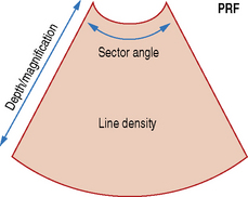
Temporal resolution is determined by the frame rate, which is the number of images displayed per second. The frame rate depends on a number of factors – these are illustrated in Figure 7.9.
Frame rate, pulse repetition frequency (PRF) and number of scan lines
The relationship between the frame rate, PRF and lines per frame is given by the following formula:

Frame rate depends upon the PRF pulse repetition frequency and the number of scan lines per image:
Factors affecting pulse repetition frequency
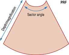
PRF depends upon image depth; an increase in image depth results in a lower PRF (see Fig. 7.10).
Factors affecting the number of lines per frame
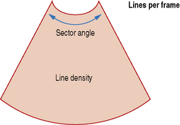
The number of lines per frame depends upon the sector angle and the line density (lines per cm). An increase in either of these increases the number of lines per frame (see Fig. 7.11).
OPTIMIZING RESOLUTION
In order to optimize spatial resolution, the highest frequency, consistent with adequate penetration, should be selected. The ultrasound beam should also be focused at the area of interest and if movement of the subject is not a problem then multiple focal zones can be used.
To optimize contrast resolution, the highest frequency, consistent with adequate penetration, should be selected, together with the appropriate preset for the area being examined. Contrast is also optimized by using the correct overall gain and TGC settings.
Temporal resolution is improved by imaging at a high frame rate. This can be achieved by reducing the sector angle and depth to include only the area of interest and selecting a single focal zone.