Chapter 8 Ultrasound interactions and attenuation
ATTENUATION
As the ultrasound beam travels through the body it loses energy. The intensity and amplitude of the sound wave decreases, and this process is known as attenuation.
The amount of attenuation that occurs will depend on the type of tissue the sound wave is traveling through. Where the molecules of the tissue are densely packed (such as bone), attenuation will be much greater than in less densely packed tissue (such as fat). Different tissues have different attenuation coefficients depending on the amount of attenuation occurring in the beam of sound.
Attenuation depends on the frequency of the sound. The higher the frequency, the greater the amount of attenuation that will occur in any given tissue.
Attenuation will occur not only in the beam of sound produced by the transducer as it propagates through tissue, but also in the returning echoes as they travel back to the transducer.
It therefore follows that returning echoes from deep within the patient will be of a much lower intensity than the initial beam of sound passing into the patient. It is for this reason that imaging equipment has a time-gain compensation (TGC) or depth-gain compensation (DGC) control, to allow for greater amplification of the weaker echoes returning from deeper within the body.
A variety of processes cause attenuation, but the five main processes to be considered are:
Absorption
This is the main factor causing attenuation of the ultrasound beam. The higher the frequency of the sound wave, the greater the amount of absorption that will occur.
Energy is transferred from the sound wave into the medium through which it is traveling.
The rate of absorption depends on the absorption coefficient of the material through which it is traveling. Bone will have a much higher absorption coefficient than soft tissue. The absorption coefficient is proportional to the frequency. As an example, the absorption coefficient for a 7 MHz frequency wave is twice that of a 3.5 MHz frequency wave, e.g. a 3.5 MHz wave traveling through 1 cm of liver will have its intensity reduced by 50%, whereas a 7 MHz wave traveling through half this distance (0.5 cm of liver) will have its intensity reduced by the same amount.
Some absorption will be due to the energy lost from the sound wave in overcoming the opposition to its forward propagation. Other absorption will occur due to a transference of energy during the compressive part of the sound wave cycle.
The majority of the lost energy will cause a rise in temperature of the tissue through which the sound is traveling. This heating effect is a potential hazard when scanning biological tissue, although it can be used to advantage, for example, by physiotherapists when using ultrasound for treatment of soft-tissue injuries.
Reflection
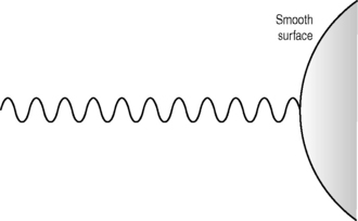
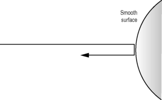
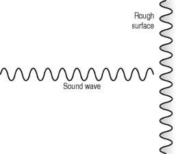
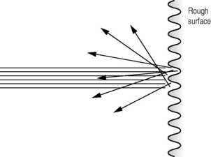
As a beam of ultrasound travels through tissue it will encounter interfaces between different types of tissue. Where these interfaces are large compared with the size of the wavelength of the sound (such as organ boundaries (see Fig. 8.1)), some of the energy of the beam is reflected back in the form of an echo (see Fig. 8.2), while the remainder of the beam carries on traveling forward through the tissue. This is known as specular reflection.
The amount of energy that is reflected depends on the size of the acoustic impedance mismatch between the two tissue types. The greater the acoustic impedance mismatch, the greater the reflected component that occurs. At the interface between the liver and kidney, approximately 1% of the incident beam will be reflected. At the interface between the liver and biliary calculi, almost 40% is reflected, whereas at the interface between the liver and air in the bowel, 99.9% of the beam will be reflected. This, therefore, will result in very little information being transmitted beyond air or calculi, due to the large percentage of reflected sound. See Chapter 4 on Acoustic impedance.
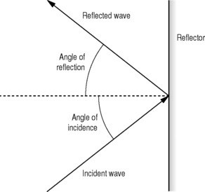
The echoes reflected from large interfaces will only be returned to the transducer if the ultrasound beam is at 90°to the boundary. The angle of incidence of the ultrasound beam will always equal the angle of reflection (see Fig. 8.3). Any interfaces which are not perpendicular to the beam will, therefore, not be visualized during the scanning procedure, because the reflected echoes will not be received by the transducer.
Scattering
When an interface is equivalent to one wavelength in size, the reflected echoes are scattered in many directions (see Fig. 8.6). Because the wavelength depends on the frequency of the sound (the higher the frequency, the shorter the wavelength), more scattering will be noted at higher frequencies.
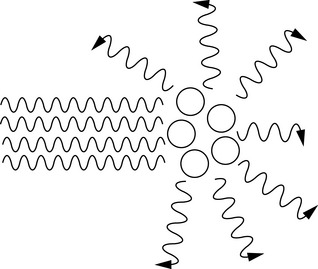
Fig. 8.6 Interfaces that are approximately one wavelength in size and where the reflected echoes are scattered in many directions
Some of this scattered energy will return to the transducer and be recorded as echoes. Organ parenchyma information will largely be composed of scattered energy (see Fig. 8.7). The majority, however, will be scattered non-uniformly in a variety of directions and not be recorded.
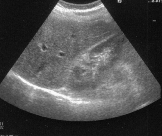
Fig. 8.7 Image showing the effects of diffuse reflection and scatter from the parenchyma of the liver and specular reflection from the diaphragm and renal boundary
When an interface is smaller than the wavelength, the scatter is equal in all directions and is known as Rayleigh scattering.
Refraction
If a beam of sound passes through an interface between two tissues where the speed of sound is different, and if the angle of incidence is not perpendicular to the interface, then the path of the beam will be deviated or refracted (see Fig. 8.8). Both factors have to be present in order for refraction to occur, therefore, with an oblique angle of incidence between tissues of different acoustic impedances, no refraction would occur if the speed of sound were the same in both tissues.
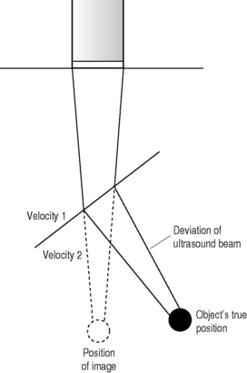
Deviations of the beam of up to 10% may occur, and this can lead to incorrect placement or misregistration of displayed echoes (see Fig. 8.8). Some of this misregistration will appear as obvious artifacts; others may be more subtle and be wrongly interpreted by the operator. Errors in measurements can also result from this refraction of the beam. The actual amount of misregistration depends on both the size of the angle of approach, and the amount of difference in speed between the two tissues.
Snell’s law
This is a formula which gives the relationship between the angle of incidence and the angle of refraction when a beam of sound passes through an interface between two tissues where the speed of sound is different (see Fig. 8.9).
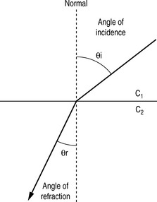

| θi = angle of incidence |
| θr = angle of refraction |
| c1 and c2 = speeds of sound in the two media |
Divergence
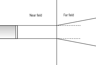
As a beam of ultrasound travels through tissue, it will diverge due to diffraction effects. This divergence will result in the same power spread over a larger area. The intensity (power/unit area) of the beam will therefore be reduced.
In addition, the returning echo wave fronts will also diverge, causing a reduction in intensity with the greater the distance they travel.
Divergence will be most notable distal to the focal zone of a focused transducer or in the far field of a non-focused transducer (see Fig. 8.10).