Chapter 14 New technology and recent advances in ultrasound imaging
In this chapter we shall look at some of the innovations in ultrasound imaging that have been introduced in the last five to ten years, and also some of the new technology which is still at the research and development stage.
DIGITAL BEAM FORMING
The beam former is the system of electronics that determines the shape of the beam. Earlier beam formers used either analog electronics or a combination of analog and digital electronics. In modern transducers the beam former is totally digital which enables the ultrasound beam to be focused with greater precision.
The amount of focusing and the position of the focus in an ultrasound beam is a function of the beam former. Focusing is achieved by applying delays to the inner elements of the group of crystals that are used to produce a composite ultrasound pulse and to receive echoes from the subject. Accurate timing of these delays is critical in producing a narrow beam focusing at the correct depth. In addition, the more accurate the timing of the delays, the less noise is produced and the better the contrast resolution.
Using analog beam formers, it is not possible to produce delay timers with the accuracy required and this limits their performance. However, beam formers are now produced using digital electronics for the time delays. In addition to producing narrower beams, digital beam formers can operate at higher frequencies and can be used with broad-bandwidth transducers.
HIGH-FREQUENCY IMAGING
High-frequency ultrasound imaging using frequencies above 20 MHz is being developed to enable the imaging of superficial structures at a very high resolution. Using conventional medical ultrasound at 5 MHz, it is possible to penetrate up to 20 cm and achieve a spatial resolution of 0.5–1.0 mm. However, with high-frequency ultrasound it is possible to image with a resolution of 50 microns (1/20 mm). The disadvantage is that because the attenuation is increased at high frequencies, penetration is reduced to a few millimeters.
The initial clinical applications of high-frequency ultrasound include the anterior chamber of the eye, intravascular ultrasound of arterial walls, skin, and cartilage.
EXTENDED FIELD OF VIEW IMAGING
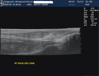
This is an imaging process which combines static B-mode techniques with real-time imaging so that a large subject area can be viewed on a single static image. Extended field of view (FOV) images are obtained by sliding the probe over the area of interest and as the images are acquired they are ‘stitched together’ electronically (Fig. 14.1). The result is a single slice image covering the whole area of interest, for example a full length view of the Achilles tendon (Fig. 14.2). Image feature recognition software is used to combine images.
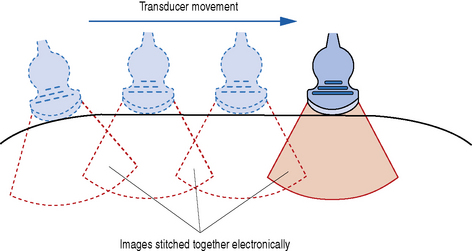
Fig. 14.1 Diagram showing how images of the subject are acquired before being electronically ‘stitched together’
This feature is now standard on most current ultrasound systems, and is particularly beneficial where large areas of the patient need to be visualized on one image, such as obstetrics or musculoskeletal imaging.
COMPOUND IMAGING
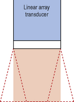
This technique combines electronic beam steering with conventional linear array technology to produce real-time images acquired from different view angles (see Fig. 14.3) Between 3 and 9 sector images are rapidly acquired and combined to produce a compound real-time image (see Fig. 14.4). Compound imaging improves image quality by reducing speckle, clutter, and other acoustic artifacts. It also gives better definition of the boundaries of structures. Because of the improved contrast resolution, compound imaging may be useful for the breast, peripheral blood vessels, and musculoskeletal applications.

THREE-DIMENSIONAL IMAGING
In conventional two-dimensional imaging the operator integrates a large number of images representing slices of the subject to form a mental 3-D image of the subject’s anatomy; however this mental 3-D picture is only available to the operator and only during the scanning process. The challenge for equipment designers is to produce a 3-D image which can be reviewed after the examination by the operator and also by other staff and patients. With 3-D ultrasound, an image of the surface of a structure is produced; this can be rotated through different planes and the surface viewed from many angles. It is also possible for the operator to ‘peel away’ layers of a 3-D image and see inside the structure.
3-D Imaging Technology
The production of a 3-D image requires a volume of tissue to be scanned. The data from this volume are then used to construct the types of image required. There are three approaches to scanning a volume of tissue: free-hand, mechanical, and electronic scanning.
Free-hand 3-D imaging
In this approach the operator sweeps the probe across the volume of interest and a series of scanning planes are recorded according to their position on the patient (see Fig. 14.5). In order to register these planes, a method of determining the position of the transducer in space is required. This can be achieved by using a receiver in the probe which will detect a magnetic field generated by a transmitter situated next to the couch (see Fig 14.6). Each image slice will have image information and position information for use in 3-D construction. Another method of determining the position of the scan plane is to use a radio transmitter and radio detection coils attached to the probe.
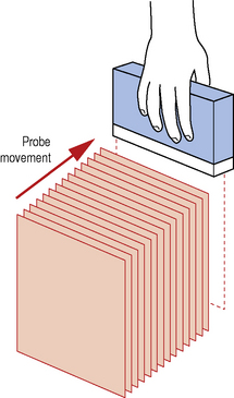
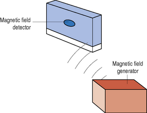
Fig. 14.6 The position of the transducer is determined by scanning within a magnetic field. A receiver in the transducer detects the magnetic field
The advantage of free-hand 3-D imaging is that a large volume can be scanned, however considerable skill is required and any measurements made are not as accurate as the automated scanning methods.
Mechanical 3-D imaging
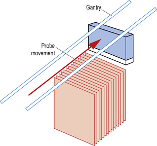
In a mechanical system the probe is attached to a motor which mechanically oscillates in a sector movement at right angles to the imaging plane (see Fig. 14.7). A volume of tissue is scanned with 2-D image data collected at regularly spaced intervals and stored for 3-D construction. In addition to the sector volume already described, parallel slice volumes (see Fig. 14.8) and rotational slice volumes are also available. The parallel slice method gives the most accurate reconstruction because the slices are equally spaced; however the scanning mechanisms are more bulky than the sector and rotational methods. With the sector and rotational volume methods, the separation between the slices increases with distance from the axis of rotation causing a decrease in resolution and less accurate 3-D reconstruction.

Electronic 3-D imaging and 4-D imaging
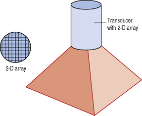
This approach makes use of a transducer with a 2-D array (see Fig. 14.9) with the data being collected from a pyramid shaped volume. This type of transducer may have over 2000 elements and collects the data from each image plane simultaneously. This enables the transducer to scan over 20 volumes per second and produce real-time 3-D images - this is known as 4-D imaging.
HARMONIC IMAGING
The aim of this method of ultrasound imaging is to reduce haze or scatter, and produce a cleaner image with higher contrast resolution. This technology takes advantage of a process known as non-linear propagation where ultrasound transmitted at the fundamental frequency is transferred into the harmonic frequencies. For example, if the fundamental frequency is 3 MHz, some of the energy would be transferred to the second harmonic (6 MHz) and third harmonic (9 MHz) frequencies, and to higher harmonics.
In harmonic imaging a broad bandwidth transducer (see Fig. 14.10) is used to transmit ultrasound at the fundamental frequency (see Fig. 14.11) and detect echoes at both the second harmonic and fundamental frequencies (see Figs 14.12 and 14.13). However, the signals produced by the fundamental frequency are filtered out and not used to form the image (see Fig. 14.14). The advantage of this method of imaging is that the second harmonic frequency contains the high amplitude echoes which arise from the axis of the beam whereas the fundamental frequency contains the low amplitude artifactual echoes and these are filtered out.
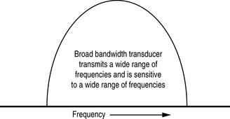
Fig. 14.10 Frequency spectrum of a broad bandwidth transducer, which shows the range of frequencies the transducer is able to transmit and the range of frequencies it is sensitive to
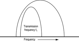
Fig. 14.11 Diagram showing the transmitted frequency spectrum (fundamental frequency) compared with the total range of frequencies available to the broad bandwidth transducer
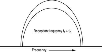
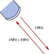
Fig. 14.13 The transducer transmits fundamental frequency ultrasound and receives both fundamental frequency and 2nd harmonic frequency ultrasound

Fig. 14.14 Diagram showing the fundamental frequency spectrum filtered out leaving the 2nd harmonic frequency spectrum for producing the image
Higher acoustic power is required and, because of the narrower range of frequencies used for image formation, pulse lengths are longer than in fundamental imaging. This results in poorer axial resolution.
This method of imaging is advantageous when scanning through large depths of tissue and is also used in conjunction with micro-bubble contrast agents. The facility is now available on most systems, however it may prove beneficial to de-activate the function during certain examinations when no perceivable benefit is obtained.
CONTRAST AGENTS
Contrast agents are used in medical imaging to increase contrast and make organs, vessels, and body cavities easier to see. In medical ultrasound contrast agents containing micro-bubbles have been found to give the highest contrast.
The micro-bubbles consist of air or inert gas encapsulated in a layer of protein or polymer. This layer prevents the bubbles dissolving too rapidly in blood or coalescing to form larger bubbles. The micro-bubbles are typically 3 μm in diameter, a similar size to red blood cells, and can therefore be transported into the smallest capillaries and across the lungs. It is important that they can survive the passage across the lungs because this enables imaging of the arterial system using a venous injection.
The micro-bubbles produce strong scattering because of the large acoustic impedance difference at the gas/blood interface. This scattering is further enhanced by the bubbles in a sound wave resonating (oscillating) at a specific frequency according to their diameter and therefore acting as a producer as well as a reflector of sound. This frequency is in the MHz range, approximately the same as the transducer frequency, and is therefore detected by the transducer.
Ultrasound contrast agents are used in a variety of clinical situations such as cardiovascular imaging to image blood vessels; gynecological imaging to image the uterine cavity and patency of the fallopian tubes; and to quantify the flow characteristics through an organ or tumor by producing wash-in/wash-out curves. Many of these examinations are now in routine use within many departments, and greatly assisting in the diagnosis of a range of conditions.
Targeted Micro-bubbles
Targeted micro-bubbles are being developed, which have special characteristics which bind them to certain cells such as inflamed cells or cancer cells. The aim is to develop a non-invasive method of imaging diseased organs. Work is also being carried out to research the possibility of using these targeted micro-bubbles to deliver drugs or genetic material, by disrupting them when they reach areas of pathology.
Contrast Agents and Harmonic Imaging
When micro-bubbles are insonated they resonate at their fundamental frequency and also at their second, third, and higher harmonic frequencies. By using harmonic imaging tuned to the second harmonic frequency of the micro-bubbles, it is possible to discriminate between the micro-bubbles and tissue. This technique increases the contrast between the micro-bubbles and normal tissue.
The contrast can be further enhanced by using pulse inversion imaging – see below.
PULSE INVERSION IMAGING
This imaging modality is used to increase the sensitivity of ultrasound to contrast agents. In conventional B-mode or harmonic imaging, only one pulse of ultrasound at a time is transmitted. In pulse inversion imaging, two pulses are transmitted, the second being an inverted copy of the first one (see Fig. 14.15). When the echoes from these two pulses are detected by the transducer they are added together.
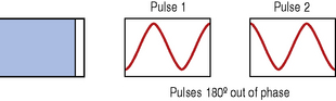
Fig. 14.15 Diagram showing two pulses being transmitted from the transducer, the second pulse being an inverted copy of the first pulse
Echoes reflected from normal tissues cancel each other out when they are added after detection (see Fig. 14.16). However, echoes from microbubbles do not cancel each other out because of the harmonic frequencies produced by the bubbles (see Figs 14.17 and 14.18). This results in an ultrasound image where the contrast produced by the micro-bubbles is significantly enhanced. It is particularly useful in small vessels where the bubbles are moving slowly, and therefore do not move far between successive transmitted pulses.
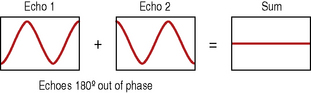
Fig. 14.16 Diagram showing how echoes reflected from normal tissues cancel each other out when they are added
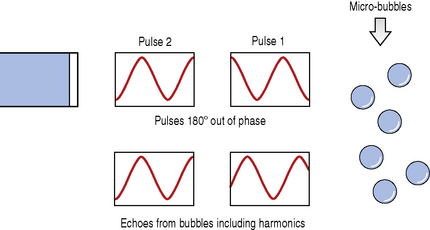
Fig. 14.17 Diagram showing echoes reflected from micro-bubbles (these echoes include some harmonic frequencies)
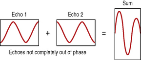
Fig. 14.18 Diagram showing how the echoes from micro-bubbles, because they are not completely out of phase, result in a high-amplitude signal when added
An advantage of pulse inversion imaging over harmonic imaging is that it is possible to use a wide range of frequencies for transmission and detection of ultrasound. This results in a shorter pulse length and therefore improved axial resolution.
ELASTOGRAPHY
Elastography is the measurement of the elastic properties of tissue, and ultrasound can be used for this purpose. It uses echo information to produce a 2-D display of the elasticity (stiffness) of tissues scanned. The elasticity of tissue is determined by applying stress, and measuring any associated movement. The stiffness of the tissues is not necessarily related to its backscatter properties, and may therefore result in contrast between tissues which is not apparent with conventional ultrasound imaging. Software in the ultrasound machine measures the degree of compression of tissue and calculates the elasticity.
The main application of elastography is in differentiating between benign and malignant tissue, malignant tissues being less elastic and therefore harder to compress than benign tissue. This technique has been used to look at breast tumors, where the tumor is imaged by ultrasound before and after compression by the probe. Elastography has also been used to examine prostate tumors and the elasticity of arterial walls; however the technique is still in its infancy and is largely used as a research tool.
TISSUE CHARACTERIZATION
Tissue characterization using ultrasound has been the goal of scientists for many years. If successful it would produce quantifiable information about the type of tissue being imaged, similar to the Hounsfield units obtained during computerized tomography (CT) scanning. The aim is to analyze the signals received from different tissues and characterize them according to their acoustic properties. However, the transmitted pulse and the echoes from the site of interest are affected by the intervening tissue, which gives a distorted signal and, until this problem is dealt with satisfactorily, tissue characterization will remain the subject of research.
TISSUE MOTION
Conventional B-mode ultrasound scanning will provide information on overall tissue motion. To obtain more information on internal tissue motions of organs, a method known as Doppler tissue imaging (DTI) has been developed. This is a variation of color Doppler imaging and can be implemented using a decreased wall thump filter to record low velocities and decrease signals from the movement of blood, in order to retain only the stronger tissue signal in the image. The technique is still in the research phase, but has the potential to provide useful information in the diagnosis of pathology of organs, particularly the heart.
PORTABLE ULTRASOUND MACHINES
Portable machines have been available since the mid 1990s. These machines were similar in size to a portable television set and were fairly limited in the range of applications offered and their performance. However, the advances in flat screen and microprocessor technology has meant that there are now laptop machines which have a range of applications and image quality approaching that of conventional scanners. In addition to this there are inexpensive handheld scanners which have applications in emergency investigations such as FAST (focused abdominal sonography for trauma) scanning.