Chapter 9 Radiation treatment planning
immobilization, localization and verification techniques
Introduction
The treatment planning process consists of a series of patient-related work tasks that eventually result in a custom plan of the external beam treatment and will enable the radiation dose prescription to be applied. The Radiation Treatment Planning (RTP) system provides a 3D dose distribution of the beams arranged around the body using a mathematical model of the megavoltage x-ray field. The composite dose map is displayed in relation to the target volume and the critical anatomical structures within the body.
Integral to the planning process are devices that ensure the treatment is reproducible on a daily basis; the most important of these is a method of reducing movement of the patient during treatment, and this is called ‘immobilization’. The specification of such a device is dependent on the area of the body for which it is required. For treatments of the head and neck, some form of immobilization device is essential to ensure reproducible set-up and to avoid displacement of the plan isocentre from its intended position. The relatively small field sizes used in the head and neck, compared with pelvic or thorax plans, requires a high degree of beam positional accuracy, because of the proximity to critical organs (e.g. eye, spinal cord), which depends on effective immobilization of the head. Other devices that facilitate reducing movement of the patient are site specific. For example, external beam radiation treatment of the breast utilizes a board that supports the patient at an inclined angle and provides hand grips that raises their arms above their head to meet the requirements for glancing beams arranged to the breast. Other devices stop the patient from moving their legs to reduce lower body movement or can make the treatment more sustainable over the few minutes of the beam exposure time.
Complete eradication of patient movement is impossible to achieve, although reducing this to within acceptable tolerance (e.g. 3 mm for head and neck, 5 mm for thorax and pelvis) is commonly achieved. Another technique to improve beam positional accuracy is to track the movement of the patient or movement of anatomical landmarks using an external device that is integral with the treatment accelerator – this method is called ‘Image Guided Radiotherapy (IGRT)’. IGRT requires monitoring of the patient using a real-time imaging device (e.g. video, ultrasound, x-ray) and the information is compared with the patient plan to correct for any positional inaccuracy. This technique enables a precise level of beam positioning control that can allow for any inadequacies in immobilization or effects of organ movement (e.g. lung displacement during respiration).
Anatomical information of the patient in the treatment position is required in order to undertake 3D treatment planning. The process of ‘localization’ includes the acquisition of either radiological images from a simulator and/or tomographic scanner (e.g. x-ray computer tomography, CT). The localization process provides external contour information and anatomical data that enable definition of planning target volume (PTV) contours and organs at risk (OAR); methods of providing this information range from x-ray CT, magnetic resonance imaging (MRI) through to positron emission tomography (PET). However, the basic requirement, to define the external contour and internal structures for treatment planning, are provided by a CT data set of the patient that can be transferred to the ‘Treatment Planning System’ (TPS) where attenuation data are converted to ‘electron density’ values for heterogeneity correction of the megavoltage beam data. Non-x-ray CT imaging modalities cannot provide this attenuation correction.
The production of an optimized treatment plan for external beam megavoltage treatment is highly dependent on the following:
• the size and shape of the PTVs
• the limiting (tolerance) dose to the critical structures (OAR)
• the positional reproducibility of the linear accelerator and couch support system
• limitation dictated by the patient’s position within the immobilization device
• selection of optimum beam parameters (e.g. field size collimator rotation).
A customized treatment plan for the patient must be checked prior to first treatment to ensure the accuracy and validity of the plan, this process is called ‘verification’.
Verification of the plan can be undertaken on a simulator where radiographic images of each beam portal can ensure the accuracy of the isocentre position and verify the beam size and shape against the treatment plan. Alternatively, a process called ‘Virtual Simulation’ allows the use of the original CT information to produce a ‘Digitally Reconstructed Radiograph’ (DRR) of the beam portal that provides a ‘virtual film’ that is comparable to the simulator image.
Patient immobilization
Patient head shells
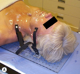
The majority of patients receiving radiotherapy to the head and neck region are immobilized using a custom made shell that accurately fits to provide effective and reproducible positioning of the head at all stages of planning and treatment. Typically, the process used to fabricate a clear plastic shell, Figure 9.1A requires a plaster cast of the patient’s head to be first produced. The transparency of the plastic enables the accuracy of fit to be checked with minor adjustments being made to ensure the shell must be a good fit, achieving the optimal position for treatment, while maintaining patient comfort.
Typically, the following steps are required to produce a full head shell:
1. the patient should assume the position to be adopted in the treatment room; this usually involves a headrest that supports the neck and inclines the head at the required angle for treatment. Separate impressions are taken of the front and back halves of the head
2. an impression of the back half of the patient’s head is made using, for example, plaster of Paris bandage or dental alginate, which covers an area up to a coronal plane at the level of the ears
3. before taking a similar impression of the front half of the head a few precautions are necessary to ensure patient comfort. The patient should breathe normally through the nose and ‘separating cream’ should be used on the skin to enable easy removal of the plaster cast. In some circumstances, a tissue-equivalent mouth insert will be required to depress and fix the tongue
4. the plaster bandage should be shaped carefully round the bony protuberances of the head in order to facilitate good fitting of the shell and to provide effective immobilization. The two plaster impressions front and back must fit uniquely together once they are removed from the patient. Further layers of plaster bandage are applied to the two halves to provide rigidity and, once hardened, are removed from the patient
5. the two halves are fixed together with further plaster bandage over the joints and the impression is filled with a thin mix of plaster and allowed to set overnight
6. the final solid cast is trimmed and sawn in half along a suitable coronal plane. The cast is now ready for vacuum forming
7. the flat surface of each half cast is placed on the vacuum forming machine. A large plastic sheet is heated and stretched into a bubble before the casts are raised and the vacuum applied to form a tight skin around the surface of the molds
8. the excess plastic is trimmed from each shell to provide a flange that enables the two halves to be held together with plastic press-studs. Side supports are molded and attached to the shell to enable it to be fixed to the treatment head support.
Thermoplastic shells
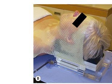
Commercial systems are now widely available that do not require vacuum forming techniques; these perforated thermoplastic materials may be softened in a hot-water bath or warm oven and shaped directly onto the patient, Figure 9.1B. This system utilizes a U-frame in which the attached thermoplastic, when heated and softened, stretches from the tip of the nose to the baseplate, where the U-frame is indexed and locked down. While this system is very easy to use and provides a snug fit for excellent fixation, it also can, in some cases, exhibit shrinkage, leading to patient discomfort due to the stretching of the thermoplastic required with this type of system. Stretching resulting from prolonged use during the course of treatment can lead to inaccuracies in set-up and, although here is a cost benefit from repeated use, sterilization requirements can limit this.
A reinforced thermoplastic is also available that improves rigidity, comfort, and immobilization. Solid thermoplastic reinforcement strips, melted into the perforated sheet, provide rigid fixation and rotational stability necessary for treatments requiring more precise immobilization such as intensity modulated radiotherapy (IMRT) and conformal radiotherapy treatments.
These thermoplastic shells are a particularly attractive alternative to the vacuum formed shells to those sites which do not have extensive pretreatment preparation facilities. The material is easily molded, transparent and the perforations allow visual assessment of the final fit.
Non-shell fixation systems
These systems of head restraint are based on a custom impression of the patient’s maxillary teeth and hard palate fixed to a plastic dental bite block (tray). Some designs incorporate a vacuum applied through the bite block that secures it to the maxillary structures; a vacuum pump is placed on the treatment couch and attaches to the mouth tray via a suction tube. Any decrease in pressure indicated by the vacuum gauge is indicative of a misplacement of the bite block. The mouthpiece is attached to two hollow carbon-fiber composite columns mounted on a baseplate by a patient-specific fixation set consisting of a transverse plate and an angle plate. Moving the plates against each other gives enough degrees of freedom to provide exact positioning. Once adjusted, the fixation set stays assembled throughout the entire treatment ensuring precise repositioning for the next fraction. A laser localizer box, consisting of side Perspex plates and top plate, are attached to the baseplate for daily set-up. Etched lines on the plate aid in visualizing the laser lines projected on the plates. This localizer box is removed prior to treatment.
This type of non-shell fixation can be as accurate as head shell methods provided that no displacement of the mouth bite occurs that could compromise the rigidity of the system. Patients that may be unsuitable for shell type immobilization, such as children and phobic patients, will often prefer this technique; however, because of limitations imposed by the system design, it is unsuitable for use with tumours of the lower oral cavity and neck.
Stereotactic frames
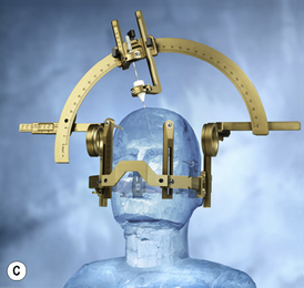
Stereotactic frames were originally designed for stereotactic intracranial surgery, biopsy and electrode placement but have since been extensively adopted for radiosurgery head immobilization, Figure 9.1C. The high level of precision required for radiosurgery, such as Gamma Knife® and X-knife® systems, necessitates a means of relating three-dimensional patient image coordinates to 3D locations in frame coordinates to submillimeter accuracy. The most common system in use is the Leksell Stereotactic System® Frame which is rigidly attached to the patient’s head using four small screws placed with local anesthetic. The frame is shown in figure 9.1C. The frame provides the basis for target coordinate determination and is used to immobilize and position the patient’s head within the radiosurgery collimator helmet. The centre coordinates of the target volume are positioned at the intersection of the beams (from 200 cobalt sources for the Gamma Knife®) so that ‘target-centering’ is always achieved within this geometrically rigid system. Relocatable versions of the stereotactic frame are also available that are closer in design to the ‘head-arc fixation’ method.
Body immobilization
Numerous techniques are available for immobilization of areas other than the head and neck. The major devices used are best discussed in relation to their site-specific needs:
Breast. Treatment of the breast commonly requires the use of three fields – two coplanar glancing beams to the breast and a supraclavicular field. All fields will often make use of the asymmetric collimators to bring one edge of each field to the beam central axis, thereby removing the effect of beam divergence from that one edge. This does not remove the penumbra, and the alignment of the superior edges of the breast fields with the inferior edges of the supraclavicular fields is critical. To achieve accuracy in this set-up requires careful positioning of the patient so that all fields can be treated without moving the patient. The use of a specially designed breast board is preferred. The device may consist of a support which inclines the patient’s upper body and provides an elbow support and/or a hand-grip for the patient to grasp while holding the arm/s above the head; all these positions can be varied to meet the individual requirements of the patient’s treatment and locked into position, linear and angular measurement scales allow the set-up to be recorded and reproduced at each fraction.
Pelvic region. This is one of the most difficult areas of the body to provide effective immobilization. Some systems utilize a single sheet of thermoplastic over the entire abdomen or pelvis that fixes to a baseplate, this is a larger version of that described for the head. An alternative to this is to use a large sealed plastic bag loosely filled with small expanded polystyrene spheres, Vac-Fix™. The bag is manually formed round the patient while the air pressure in the bag is gradually reduced using a vacuum pump. At approximately half atmospheric pressure, the bag becomes rigid and ‘fits’ firmly round the patient, preventing any significant movement. The rigidity can be maintained throughout a course of treatment and until the vacuum is released, when the bag and contents may be re-used for another patient. A variety of shapes and sizes of bag are available to immobilize any part of the anatomy or the whole of the patient, for total body irradiation (TBI), for example. The attenuation in the polystyrene is minimal, but being opaque, consideration must be given to the beam entry ports during the initial evacuation. Radiation damage to the plastic will eventually cause vacuum failure and necessitate the replacement of the bag. Other devices, such as ‘ankle stocks’ and ‘foot rests’, can minimize movement by impeding body rotation or slippage on the treatment couch. The use of a ‘belly-board’ for prone patients, providing a cut-out in the patient support which allows the abdomen to fall anteriorly, ensures that much of the radiosensitive small intestine falls out of the high dose region.
Thorax. For modern radiotherapy, the problems imposed by respiratory movement can be considerable. Normal breathing causes movement of the chest wall and introduces uncertainties with regard to target volume position during treatment. These uncertainties are usually allowed for by introducing appropriate margins to the volume definition at the planning phase. However, these increased margins may have a significant effect on normal tissue doses and therefore have a limiting effect on the target dose. Effective compensation for these movements may involve either tracking of markers on the skin surface or identification of internal lung movement. Tracking the movement of the chest can be achieved using markers that can be followed using video cameras and calculating coordinate shifts that trigger a treatment pause if tolerances are exceeded. The tracking of internal organ movement is called ‘Image Guided Radiotherapy’; these systems utilize either ultrasound or x-ray tomographic imaging methods to monitor and compare organ positions with the original CT planning images. This topic will be discussed further later in this chapter.
Volume definitions
Accurate treatment depends on voluming. The parameters used in defining treatment volumes are described in detail in two documents published by the International Commission on Radiation Units and Measurements (ICRU), Reports 50 and 62 ‘Prescribing, Recording and Reporting Photon Beam Therapy’ [1, 2].
The following are a transcript of the definitions:
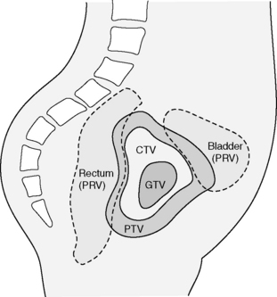
Gross tumour volume (GTV) – is the gross palpable or visible/demonstrable extent and location of the malignant growth.
Clinical target volume (CTV) – is a tissue volume that contains a GTV and/or subclinical microscopic malignant disease, which has to be eliminated. This volume thus has to be treated adequately in order to achieve the aim of therapy: cure or palliation.
Planning target volume (PTV) – is a geometrical concept, and it is defined to select appropriate beam size and beam arrangement, taking into consideration the net effect of all the possible geometrical variations and inaccuracies in order to ensure that the prescribed dose is actually absorbed in the CTV.
Treatment volume – is the volume enclosed by an isodose surface, selected and specified by the radiation oncologist as being appropriate to achieve the purpose of treatment.
Organs at risk (OAR) — are normal tissues whose radiation sensitivity may significantly influence treatment planning and/or prescribed dose.
ICRU62 is the supplementary report to ICRU 50 and discusses in more detail the complex factors that account for delineation of the PTV. An Internal Margin (IM) is defined to accommodate for the variations in size, shape and position of the CTV as a result of anatomical variations caused by organ movement. An additional Set-up Margin (SM) must be then added to allow for the uncertainties of patient–beam position. Whereas the IM is required to allow for a physiological process, the SM is required to allow for the technical factors that cause uncertainties. The SM may be reduced by improved immobilization of the patient and improved set-up accuracy. The IM can only be reduced through techniques such as ‘respiratory gating’ or ‘image guided radiotherapy’. The organs at risk (OAR) volumes will also exhibit the same uncertainties in position and these will also require a margin to be added – the concept of Planning Organs at Risk Volume (PRV) is analogous to the PTV (See figure 9.2).
Non-CT contouring devices
Contours are all important in producing dose distributions. The value of radiation treatment planning depends on the reproducibility of the shape of the patient on a day-to-day basis throughout the course of treatment. The couch where the patient contour will be taken therefore should be identical in every respect to the couch on which that patient will be treated. It is imperative that the patient is correctly positioned before the contour is taken for planning purposes. Since the advent of radiotherapy treatment planning, a variety of physical devices has been available for taking patient contours. The simplest of these consists of a material (lead strip, flex curve) that can be bent around the patient and retains the shape while being transferred to paper in order to trace the contour.
Adjustable templates have been used that allow for more complex shapes to be transposed. A large number of adjustable pins or rods (3 mm diameter) held in a frame can accurately reproduce the surface shape in an axial plane. The frame is transferred to a drawing board and the contour traced onto paper.
Another simple method of obtaining a contour(s) from an immobilization shell is by fixing the shell within a frame so that a movable pin that can rotate around the plane to be contoured provides radial distance measurements; this system relies on radial coordinate measurements to transpose the contour shape of the required plane to paper. Many of these physical devices involving the use of contact techniques have been superseded by non-contact devices such as laser imaging/optical devices or through the use of computerized axial tomography; the latter will be described in detail in the following sections.
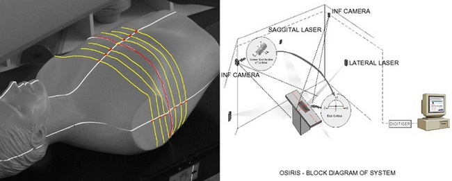
Recently, the use of optical systems, which have the benefit of no direct patient contact, have been introduced to provide both single and multiple contours of the patient in the treatment position. These systems are commonly installed within the simulator room and utilize the in-room alignment lasers (two laterals and one sagittal) that project both an axial and a vertical line on the patient’s skin. Multiple views of these laser projections can be imaged by using four CCD cameras, mounted at ceiling height in each corner of the room, focused on the laser lines. Software manipulation of these four images enables a reconstruction of an axial contour and a sagittal contour. Multiple contours of the patient can be acquired by moving the couch either longitudinally (axials) or laterally (sagittals) and capturing images at each position.
This remote method of contour acquisition has many advantages over the physical methods described above; the key benefits are its inherent non-contact with the patient and the technique requires no manual handling of a device. Optical systems provide digital images of the patient’s external contour that can quickly and easily be transferred to the TPS and are generally compatible with the planning software. The ability of these systems to provide 3D skin contours are particularly useful in breast planning where CT planning may be less practical because of limitations of the CT scanner to accommodate patients in the position required for treatment to the breast (see figure 9.3).
Physical simulation
The treatment simulator is essentially a diagnostic x-ray unit that emulates an isocentric linear accelerator’s geometrical movement. The simulator has been an aid to radiotherapy for nearly half a century, and enables highly accurate localization of the target volume, the verification of the proposed treatment plan and, in some cases, even precise visualization of the organs at risk.
The unit allows real-time imaging of the beam portal and a facility to produce x-ray films of each treatment field.
The movements of a radiotherapy simulator are defined in the publication IEC 1217- ‘Radiotherapy Equipment – coordinates, movement and scales’ [3]. A physical simulator should have at least as good, or better, accuracy in positioning as the treatment unit and its mechanical tolerance must be excellent (e.g. an isocentre accuracy of 1 mm diameter sphere should be possible). The simulator geometry should permit all the required beam directions and field definitions that are achievable on a linear accelerator. Modern physical simulators (e.g. Varian Acuity™) do not have the limitations of the image intensifier systems that have been used for decades. The availability of an amorphous silicon panel to provide a digital imaging device has resulted in simulators that are almost identical to the therapy unit and have few movement constraints.
The simulator couch again needs to be identical to that used on the therapy unit and should have the same range of lateral, longitudinal, vertical and rotational movements. Coordinate scales between the simulator and linear accelerator must be identical. The ability to accommodate all treatment accessories and ensure precise emulation of the patient’s position is essential.
The size of image that can be obtained during physical simulation is limited by a number of factors: the physical size of the image detector, the focus–axis distance, the focus–detector distance and the ability to stitch images together using a merge function. Dual and Quad merge techniques allow the acquisition of an image larger than the size of the imager (which is typically 30 × 40 cm2). The enlarged image is created by moving the detector plate and acquiring multiple images all of which contain the beam central axis. Software enables these images to be referenced to this common central axis point and aligned accurately to provide extended images in both the horizontal and vertical directions. This facility is particularly useful for large pelvic fields or extended spine fields. Automatic merging of multiple images is less successful when there are significant differences in absorption within the images, e.g. a pelvis where large air gaps cause high contrast gradients.
During the localization procedure, the simulator is used much like a diagnostic x-ray unit where the patient is positioned on the couch in the treatment position and moved while imaging the anatomy. The desired location for field placement requires x-ray visualization in real-time until the required position is reached. In order to minimize radiation exposure to the patient during this procedure, a utility called ‘motion control’ is available. This function allows the control of field placement, e.g. x/y blades, collimator or field centre by adjusting these parameters on the captured (frozen/stored) image. Subsequent live activation of the imaging system initiated an automatic change to the parameter values and patient position on the physical simulator. The advantage of this function is that clinical decision and minor adjustments can be made on the captured image with a final check made with an x-ray exposure.
A typical head and neck physical simulation procedure is described below (although where a CT based facility is available, this offers a superior method of anatomical localization and contouring).
Localization
The patient is required to adopt the position on the simulator that is optimal for treatment delivery. The immobilization shell is then applied and final checks should be made to ensure that the patient is comfortable, that the head position is appropriate for the treatment being planned and that the contour of the shell fits accurately to the patient. Magnification markers of a known size may be applied to the shell for use during the planning stages.
The couch position is then moved so that the isocentre is approximately incident upon the centre of the proposed target volume using surface anatomical landmarks. This can then be adjusted using fluoroscopy. Two orthogonal films/images should be taken (typically an AP and a lateral view, although any orthogonal arrangement may be used). It is usually prudent to record positioning details at this stage along with the film exposure factors.
Prior to moving the couch, a contour is taken using an appropriate contouring method which ensures that the film data and the contour data are coincident. This may be taken while the patient is on the couch or, alternatively, the lasers may be used to mark the plane on the shell surface so that a contour can be taken from the shell at a later time.
The size and position of the volume is marked on each film and the data transferred to the TPS for calculation and plan optimization. The plan should be accepted by the oncologist prior to verification.
Verification
Once the optimal treatment plan has been produced based upon the contour and geometric data from the images, the plan must be verified prior to commencement of treatment.
The patient re-attends the simulator and adopts the treatment position using the immobilization shell and positioning details recorded from the localization procedure. Using the parameters from the treatment plan, each field is set up in turn, applying the correct size, shape and direction of the beam. Using fluoroscopy, a comparison can be made between the volume marked at localization and that achieved during verification. Local protocols will specify tolerances for positional accuracy.
Using the light projected field display, the entry points and field borders can be transferred to the shell to ease treatment set-up on the linear accelerator. A verification film/image may be taken as confirmation of the final field portal to be delivered and gantry couch and field data may be transferred via a network to the linear accelerator.
If the beam arrangement is particularly oblique, it may be difficult to interpret the anatomy seen during fluoroscopy and it may be necessary to supplement the beam portal information with an AP and lateral view as a means of accurately confirming the position of the isocentre.
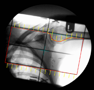
It is difficult to verify intricate beam shaping and multileaf collimator (MLC) configuration using conventional simulation, but this may be achieved either by using a physical device, attached to the accessory mount, which has radiopaque markers to define the leaf positions or by using a digital shape projection device (Figure 9.4).
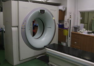
CT simulation
The term ‘CT Virtual Simulation’ was first introduced in a publication by George Sherouse in 1987 [4] who recognized that a suitable software package in conjunction with a diagnostic CT scanner could be developed that would emulate a conventional radiotherapy simulator. In the early 1980s, the use of CT scanners in treatment planning amounted to providing axial images that could be transferred to the TPS. The process of plan optimization and verifying the set-up before treatment was purely a role for the TPS and the physical simulator with no significant manipulation of the 3D CT data to augment this process. At this time, the use of the Beam’s Eye View (BEV) allowed the visualization of a beam shape relative to the target contour, bony anatomy and other contoured organs. The BEV gave the planner the ability to optimize beam positions, shapes and orientation in the same manner as could be achieved radiographically on the simulator.
In 1983, Goitein et al [5] introduced the use of the Digitally Reconstructed Radiograph (DRR), a virtual radiograph or film of the patient. The calculation of DRRs is computationally intensive consisting of ray-line projection, interpolation, line integration and gray scale mapping of the CT data. For many years, the inability for computers to provide fast array processing slowed the introduction of virtual simulation into the treatment planning process.
The automatic registration of the BEV and DRR have provided powerful tools to enable the planner to achieve on the TPS what was available on the simulator but with the added benefits of CT visualization (see figure 9.5A). However, for practical use, the speed of DRR calculation would have to be sub-second to give the planner ‘the feel of a simulator’.
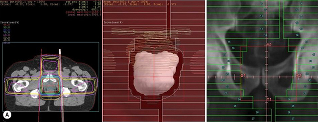
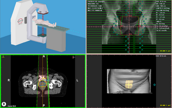
Figure 9.5 (A) Beams Eye View (BEV) on a Treatment Planning System with Digitally Reconstructed Radiograph (DRR) on Virtual Simulator; (B) Screen shot of Virtual Simulator with surface rendering and transverse slice.
In the early 1990s, specialized graphics workstations were introduced that allowed fast 3D array processing for ray-tracing, volume rendering and image reconstruction. Commercial systems became available at this time and, with the rapid improvement in PC processor speeds over the past 10 years, have resulted in CT Virtual Simulation becoming more available and widely used in radiotherapy (see figure 9.5B).
CT Virtual Simulation is a combination of the physical process of using a CT scanner as an alternative to the physical simulator described above and the virtual process of simulator emulation using software programs.

CT localization requires the patient to be supported and immobilized in the same position as for radiotherapy treatment. This can be more difficult compared with the conventional simulator which is designed specifically to mimic the linear accelerator patient support systems. The CT scanner must have a flat-top couch that can accept all these patient support accessories.
The process of marking the patient is facilitated by a laser system consisting of two fixed lateral lasers, the plane of these lasers being offset from the CT aperture plane by typically 500 mm, and a sagittal laser that can be moved laterally to overcome the fixed nature of the CT couch. The laser system can define the origin of a coordinate system that relates to the treatment machine coordinate system by shift distances or, in some cases, define the precise plan isocentre coordinates.
CT scanners used for simulation are invariably diagnostic scanners that have been adapted with flat table-top and external (to the gantry) laser systems. However, the advent of ‘large bore scanners’ specifically for radiotherapy planning have enabled these systems to be not only complementary but adopted as an alternative to the physical simulator. These new scanners have apertures of 80–85 cm compared with the conventional 70 cm and have scan field of view (SFOV) that are 10–15 cm larger than the diagnostic SFOV. For breast treatments, where the ipsilateral arm is raised above the head and subtends an angle close to 90°, then the large aperture scanners provide increased functionality (see figure 9.6).
The CT simulation process requires a scout (pilot) view to be taken in order to identify the required scan volume and suitable scan parameters. Axial image acquisition can be performed in either axial or spiral mode; the latter enables a continuous movement of the tube/couch rather than stepped movement in the axial mode. The patient CT study is passed to the virtual simulation workstation.
Virtual simulation
The physical simulator provides a real-time image using either a fluoroscopic screen with image intensifier or an amorphous silicon panel; this may be followed by exposure of a radiographic film to provide localization of the treatment volume, visualization of the treatment field and verification of the plan design. Successful implementation of the virtual form of this simulator depends on software manipulation of the CT data.
The CT simulator equivalence to the physical simulator includes software capabilities to contour target volumes and critical structures, placement of treatment isocentre, beam design and generation of digital reconstructed radiographs (DRR). Many of the software control features are also incorporated into 3D planning systems but do not include the ability to provide coordinate information that relates to the patient position on the scanner couch and the provision to mark the isocentre and reference points.
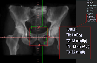
The treatment planning portion of the CT simulation process starts with the definition of a treatment reference point that can either coincide exactly with the position of the isocentre or alternatively can be an estimate of its position. The former method will require the definition of the target volume to define precisely the treatment isocentre and will require the oncologist to be present; whereas the latter method does not require the target volume to be defined and the final isocentre position can be found using ‘shift coordinates’. These shift distances,Figure 9.7 are relative to the reference point and can be applied at the first treatment in order to align precisely the isocentre to the target. The shift coordinate method is commonly used in a busy department where there is limited time to wait until targets are contoured or where the oncologist is not available during the scanning session.
A typical head and neck CT simulation procedure
Localization requires the immobilization shell to be attached to the flat CT couch in order to emulate exactly the patient positioning on the treatment machine. Careful consideration should be given to the design of the head fixation device to enable compatibility between the CT and accelerator table supports.
The scanning parameters are usually a trade-off between maximizing DRR resolution and keeping the number of slices to a manageable size (typically 3 mm slice thickness and 1.5 spiral pitch). The scanning extent is determined from the pilot (scout) view and the external contours are often produced at a remote virtual simulation workstation while previewing the scanned slices.
A reference slice plane is selected and the ‘patient reference origin’ coordinates created and transferred to the CT couch and/or lasers. The CT longitudinal couch, vertical couch and sagittal laser positions are set to define the ‘patient reference origin’ and the patient is marked. The patient session is now finished. An alternative approach is to mark the patient before scanning and to set this position as the ‘patient reference origin’.
Virtual simulation requires marking of the GTV, CTV, PTV and OARs; the isocentre and field parameters can then be defined using the TPS. The plan is sent for calculation and optimization to the TPS and exported back to the virtual simulator workstation for verification. The DRRs for all beams are printed (laser imager) and approved by the oncologist.
‘Shift coordinates’ are printed from the relationship between the isocentre to ‘patient reference origin’ coordinates. These are transferred to the treatment machine with the plan details. Worksheets and DRRs are printed (see figure 9.7).
The advantages of CT virtual simulation can be summarized as follows:
• full 3D simulation allowing unique verification of beam coverage and avoidance in 3D
• beams can be simulated and verified that are not possible with conventional simulation, e.g. vertex fields
• the verification image – the DRR – can contain more information than conventional simulation and can be manipulated to enhance tumour visualization
• there is a much closer connection to diagnostic information with CT simulation allowing integration of multimodality images.
During the early use of CT simulation, it was evident that the inability to image organ movement (e.g. lung) was a significant disadvantage over physical simulation’s fluoroscopy. However, the improvement in image acquisition and reconstruction speeds has provided the ability to follow respiratory movement. The technique is often called ‘respiratory gated acquisition and 4D viewing’, this method enables images to be acquired at a rate of more than 16 frames per second that enables the full movement of the patient’s diaphragm to be visualized within a movie loop. The definition of lung tumour margins can now be assessed in 3D.
Multimodality images for planning
CT imaging plays a crucial role in radiotherapy planning as it provides the electron density information that is required to correct the absorbed dose for the different tissues through which the beams will pass.
CT imaging also provides excellent definition between tissues having marked differences in x-ray attenuation values (e.g. air/bone/soft tissue), however, the contrast of these images is poor for structures with similar electron densities (e.g. tumour/soft tissue).
Magnetic resonance imaging (MRI) is based on the measurement of radiofrequency radiation resulting from transitions induced between nuclear spin states of hydrogen atoms (protons) in the presence of strong external magnetic fields. Unlike CT, where the signal intensity is dependent on x-ray attenuation and its contrast on the electron density of tissues, MRI depends on the intrinsic tissue properties associated with proton densities and spin relaxation times. Therefore, MRI has the ability to differentiate between tissue of similar density thus providing better delineation, not only of tumour extent, but also of the adjacent critical soft tissue organs.
MRI also provides unrestricted multiplanar, volumetric, vascular and functional information.
Some of the problems associated with using MRI for treatment planning are:
1. inherent image distortion, particularly at the periphery of the image (typically 3 mm for heads and up to 15 mm for pelvic images)
2. pixel intensities are not related to electron density values and therefore cannot be used for heterogeneity correction (i.e. density/dose) when calculating treatment plan dose distributions
3. the physical restrictions of the MRI scanner mean that a patient cannot be easily positioned in the treatment position. A quantitative method called image registration is used that provides fusion of CT and MRI image studies.
MRI data are transferred to a TPS where the therapy CT images and the MRI images are registered. Manual and automatic methods of registration are now available as part of sophisticated software systems provided with CT simulators. The manual methods involve matching fiducials that are visualized on both CT and MRI; these fiducials are opaque markers or bony structures so that image translation in the three coordinates directions achieve a match between the two studies. The accuracy of image registration can be assessed by the accuracy to which the fiducial markers match.
Once the two image data sets are matched then volume contouring on the MRI images is automatically translated to the CT study. This technique provides the advantages of the MRI images for tumour delineation while maintaining the CT study for accurate calculation of the treatment dose distribution.
Automatic registration methods such as ‘mutual information’ use rigid and non-rigid matrix transformations that are able to compensate for rotational as well as translational differences between the two image sets.
New imaging modalities that provide ‘functional’ or ‘tumour kinetic’ information for radiotherapy treatment planning are becoming widely accepted. Positron emission tomography (PET) and single photon emission CT (SPECT) produce nuclear medicine images that enable improved staging of malignant disease and improved treatment planning by ensuring that gross tumour volumes are more accurately defined. Information from these functional imaging modalities can be used to design more conformal radiation dose distributions and to prescribe additional dose to specific tumour microregions.
The specific activity of the radiopharmaceutical fluoro-2-deoxyglucose (18F-FDG) produces uptake in malignant tissue that enables highly accurate determination of the extent of solid tumour spread. FDG is taken up by glucose transporters and its concentration can be measured (images) by the retained activity within various tissues. FDG uptake correlates strongly with the presence of cancer.
The introduction of combined PET/CT scanners has improved the availability of this new modality. The PET images are superimposed upon the CT images, both of which are simultaneously acquired during a single scan session. Planning can be performed either in treatment position, requiring modifications to the scanning protocols, or in diagnostic position with image registration being used to accommodate the change in patient position between functional image and treatment planning patient position.
Specialized software can register the PET/CT study with the therapy planning CT study to enable contours on the PET images to be transposed to the planning images.
There is increasing evidence that, in many clinical situations, radiotherapy treatment may be planned more accurately if supplementary functional images of the patient are available. In practice though, the lack of access to PET and the problem of image registration have restricted the use of combined anatomical and functional information:
• PET is prohibitively expensive, which has limited its routine clinical use to only larger oncology facilities
• multimodality image registration is a difficult problem, which is further complicated by the significant anatomical changes that may occur between the different imaging sessions due to surgery, chemotherapy, patient weight change or fluid collection.
Portal verification and image guided treatments
Portal imaging
Confirmation of the accuracy of the delivered beam is an essential part of quality assurance. This is achieved primarily by imaging the beam portal using the linear accelerator before, during or after a treatment exposure.
This can be achieved using a choice of film. Therapy verification film, a slow film housed in a light proof packet, can be left in place for the full treatment exposure. Alternatively, a faster film housed in a cassette with stainless steel intensifying screens requiring a smaller incident dose can be used, the advantage of this is that it is possible (though perhaps not practical) to develop the image and analyze the outcome prior to delivering the full treatment dose.
The disadvantages of film are the need for on-site processing facilities, the time delay in processing, inability to manipulate the image quality without re-exposure and the resultant long-term storage considerations.
Hardcopy films are now being superseded by electronic or digital forms of imaging. Solid state devices or electronic portal imaging devices (EPID) are now becoming integral components of the linear accelerator. These devices may consist of an amorphous silicon detector panel housed on a retractable arm which is an integral component of the linear accelerator gantry. In this way, the panel is always perpendicular to the beam central axis thus avoiding image distortion. Detector panels have a physical size of 30 × 40 cm and this allows practical imaging of fields, typically 20 × 25 cm. Image quality from amorphous silicon devices is considerably superior to that which can be achieved with film or optical camera-based systems.
Protocols for the frequency of imaging are determined locally, though typically, these consist of imaging the fields for the first three to five fractions to establish accuracy and reproducibility and then periodically throughout the rest of the course to ensure consistency.
Analysis of the images produced may be qualitative, i.e. an ‘eyeball’ assessment in conjunction with the software measuring tools or, increasingly, may utilize the assistance of an automatic image registration tool to provide quantitative displacements. The image registration or matching process requires user defined anatomy to be outlined on a reference image (typically the DRR or the conventional simulation image). The same anatomical features are then outlined on the portal image and the software will overlay these contours thus providing a field edge displacement value for the lateral, longitudinal and rotational positions. As a result, it is possible to determine whether the isocentre position is within predetermined tolerances or whether adjustment is required.
There are many advantages to digital imaging systems; physical storage problems are removed – though consideration must be given to the need for future data retrieval. Software tools can be used to manipulate the image to aid viewing and analysis, multiple users can view the image and remote access facilities can be implemented. From a treatment delivery aspect, however, the biggest advantage is the ability for on-line assessment of images and immediate adjustment of patient position to achieve greater accuracy.
Image guided radiotherapy
Conformal radiotherapy depends on geometrical and dose shaping to optimize the dose distribution to the known planning target volume. Techniques to achieve this involve the use of multileaf collimation to shape each field to a beam’s eye projection of the PTV (geometric conformality) and intensity modulation of the beam (IMRT) to achieve dose shaping of the beam (dose conformality). These methods do not take into account the fourth dimension to radiotherapy, ‘time’, which can extend from seconds to days.
A number of time-related factors introduce significant uncertainties in radiotherapy:
1. the movement of target and critical tissues during treatment (seconds – minutes).
2. the movement of organs between treatment fractions (days)
3. the dynamic movement of the beam delivery method (seconds – minutes).
The interplay between the dynamic beam delivery motion and tissue motion during treatment can result in both over- and underdosage of the target volume.
Two questions that have involved considerable debate are: What are the effects of organ motion on treatment planning images? And how can we acquire information on organ motion? The advent of ultra-fast CT acquisition from multislice scanners has enabled time dependent organ position data to be captured This large quantity of data can be used during the treatment planning process but the contouring of the hundreds of image slices is not possible using conventional manual methods. Automatic organ tools (segmentation methods) are being developed that enable tracking of organ movement (4D imaging).
During treatment, these organ movements must be also monitored in order to correlate with planning (verification) data.
Four methods of image guided techniques are available:
• radiopaque markers that can be tracked using video cameras
• ultrasound systems that determine organ positions prior to treatment
• diagnostic x-ray systems mounted on the linear accelerator that can provide orthogonal images or CT (cone beam reconstructed) images
• treatment-room CT scanners that are adjacent to the linear accelerator and can provide pretreatment or post-treatment CT images.
[1] ICRU Report 50. Prescribing, recording and reporting photon beam therapy. International Commission on Radiation Units and Measurements; 1993.
[2] ICRU Report 62. Prescribing, recording and reporting photon beam therapy. International Commission on Radiation Units and Measurements; 1999. (supplement to ICRU Report 50)
[3] IEC 1217. Radiotherapy equipment – coordinates, movement and scales. IEC; 1996.
[4] Sherouse GW, Mosher CE, Rosenman J, Chaney EL. Virtial Simulation: Concept and Implementation. The Use of Computers in Radiation Therapy. Bruinvis et al, editors. Elsevier, North-Holland; 1987
[5] Goitein M., Abrams M. Multi-dimensional Treatment Planning: Beam's Eye View, Back Projection, and projection through CT sections. Int J Radiat Oncol Biol Phys. 1983;9:789–797.