Positioning Principles

Evaluation Criteria

The goal of every technologist should be to take not just a “passable” radiograph but rather an optimal one that can be evaluated by a definable standard, as described under evaluation criteria.

An example of a four-part radiographic image evaluation as used in this text for a lateral forearm is shown on the right. The positioning photo and the resulting optimal radiograph (Figs. 1-99 and 1-100) are shown for this lateral forearm, as described in Chapter 4.

Evaluation Criteria Format

The technologist should review and compare radiographs using this standard to determine how close to an optimal image was achieved. A systematic method of learning how to critique radiographs is to break the evaluation down into these four parts.

1. Anatomy demonstrated: Describes precisely what anatomic parts and structures should be clearly visualized on that image (radiograph).

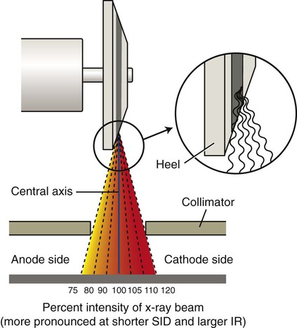
2. Position: Generally evaluates four issues: (1) placement of body part in relationship to the IR, (2) positioning factors that are important for the projection, (3) correct centering of anatomy, and (4) collimation

3. Exposure: Describes how exposure factors or technique (kilovoltage [kV], milliamperage [mA], and time) can be evaluated for optimum exposure for that body part. No motion is a first priority, and a description of how the presence or absence of motion can be determined is listed. (Motion is included with exposure criteria because exposure time is the primary controlling factor for motion.)

4. Image markers: A fourth area of evaluation involves image markers. Anatomic side markers, “Right” or “Left,” patient position, or time markers must be placed correctly before exposure so that they are not superimposed over essential anatomy.

image
Fig. 1-99 Accurate positioning for lateral forearm.
image
Fig. 1-100 Lateral forearm.

Sample Lateral Forearm Criteria

Evaluation Criteria

Anatomy Demonstrated:

• Lateral projection of entire radius and ulna; proximal row of carpals, elbow, and distal end of humerus; and pertinent soft tissues such as fat pads and stripes of wrist and elbow joints

Position:

• Long axis of forearm aligned with long axis of IR • Elbow flexed 90° • No rotation from true lateral as evidenced by the following: • Head of the ulna should be superimposed over the radius • Humeral epicondyles should be superimposed • Radial head should superimpose the coronoid process with radial tuberosity seen in profile • Collimation to area of interest

Exposure:

• Optimum density (brightness) and contrast with no motion will reveal sharp cortical margins and clear, bony trabecular markings and fat pads and stripes of the wrist and elbow joints

Image Markers:

• Patient identification, R or L side marker, and patient position or time markers should be placed so that they are not superimposed over essential anatomy

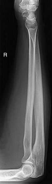
Image Markers and Patient Identification

A minimum of two types of markers should be imprinted on every radiographic image. These are (1) patient identification and date and (2) anatomic side markers.

Patient Identification and Date (Film-Screen Cassette [ANALOG] Systems)

Generally, this patient information, which includes data such as name, date, case number, and institution, is provided on an index card and is photoflashed on the film in the space provided by a lead block in the film cassette. Each cassette or film holder should have a marker on the exterior indicating this area where the patient ID, including the date, will be flashed (Fig. 1-101).

Throughout this text, the preferred location of this patient ID marker is shown in relation to the body part. A general rule for chests and abdomens is to place the patient ID information at the top margin of the IR on chests and on the lower margin on abdomens (see arrows on Fig. 1-102). The patient ID marker must always be placed where it is least likely to cover essential anatomy. The anatomic side markers should always be placed in a manner on the IR so that they are legible and esthetically correct. It must be within the collimation field so that it provides a permanent indicator of correct side of the body or anatomic part.

Digital systems

With storage phosphor cassette–based systems, often a bar-code system imprints the patient information before or after exposure. Care must be taken so that this area does not obscure the essential anatomy that is being demonstrated. With flat panel detector with thin film transistor (FPD-TFT) systems and charged couple device (CCD) systems, patient identification is typically entered before exposure.

Anatomic Side Marker

A right or left marker must also appear on every radiographic image correctly indicating the patient's right or left side or which limb is being radiographed, the right or the left. This may be provided as the word “Right” or “Left” or just the initials “R” or “L.” This side marker preferably should be placed directly on the IR inside the lateral portion of the collimated border of the side being identified, with the placement such that the marker will not be superimposed over essential anatomy.

These radiopaque markers must be placed just within the collimation field so that they will be exposed by the x-ray beam and included on the image.

The two markers, the patient ID and the anatomic side marker, must be placed correctly on all radiographic images. Generally, it is an unacceptable practice to write or annotate digitally this information on the image after it is processed because of legal and liability problems caused by potential mismarkings. A radiograph taken without these two markers may have to be repeated, which results in unnecessary radiation to the patient, making this a serious error. In the case of digital images, annotating the image to indicate side markers is an unacceptable practice. The exposure should be repeated to ensure correct anatomy was imaged.

image
Fig. 1-101 Patient identification information.
image
Fig. 1-102 Correctly placed side markers and patient identification marker (patient's right to viewer's left).

Additional Markers or Identification

Certain other markers or identifiers also may be used, such as technologist initials, which generally are placed on the R or L marker to identify the specific technologist responsible for the examination. Sometimes the examination room number is also included.

Time indicators are also commonly used; these note the minutes of elapsed time in a series, such as the 1-minute, 5-minute, 15-minute, and 20-minute series of radiographs taken in an intravenous urogram (IVU) procedure.

Another important marker on all decubitus positions is a decubitus marker or some type of indicator such as an arrow identifying which side is up. An “upright” or “erect” marker must also be used to identify erect chest or abdomen positions compared with recumbent, in addition to an arrow indicating which side is up.

Inspiration (INSP) and expiration (EXP) markers are used for special comparison PA projections of the chest. Internal (INT) and external (EXT) markers may be used for rotation projections, such as for the proximal humerus and shoulder. Sample markers are shown in Fig. 1-103.

Professional Ethics and Patient Care

The radiologic technologist is an important member of the health care team who is responsible in general for radiologic examination of patients. This includes being responsible for one's actions under a specific code of ethics.

Code of ethics describes the rules of acceptable conduct toward patients and other health care team members as well as personal actions and behaviors as defined within the profession. The ARRT code of ethics is provided in the box on this page.

image
Fig. 1-103 Sample procedure markers.

American Registry of Radiologic Technologists Code of Ethics*

The Code of Ethics forms the first part of the Standards of Ethics. The Code of Ethics shall serve as a guide by which Certificate Holders and Candidates may evaluate their professional conduct as it relates to patients, healthcare consumers, employers, colleagues, and other members of the healthcare team. The Code of Ethics is intended to assist Certificate Holders and Candidates in maintaining a high level of ethical conduct and in providing for the protection, safety, and comfort of patients. The Code of Ethics is aspirational.

1. The radiologic technologist acts in a professional manner, responds to patient needs, and supports colleagues and associates in providing quality patient care.

2. The radiologic technologist acts to advance the principal objective of the profession to provide services to humanity with full respect for the dignity of mankind.

3. The radiologic technologist delivers patient care and service unrestricted by the concerns of personal attributes or the nature of the disease or illness, and without discrimination on the basis of sex, race, creed, religion, or socio-economic status.

4. The radiologic technologist practices technology founded upon theoretical knowledge and concepts, uses equipment and accessories consistent with the purposes for which they were designed, and employs procedures and techniques appropriately.

5. The radiologic technologist assesses situations; exercises care, discretion, and judgment; assumes responsibility for professional decisions; and acts in the best interest of the patient.

6. The radiologic technologist acts as an agent through observation and communication to obtain pertinent information for the physician to aid in the diagnosis and treatment of the patient and recognizes that interpretation and diagnosis are outside the scope of practice for the profession.

7. The radiologic technologist uses equipment and accessories, employs techniques and procedures, performs services in accordance with an accepted standard of practice, and demonstrates expertise in minimizing radiation exposure to the patient, self, and other members of the healthcare team.

8. The radiologic technologist practices ethical conduct appropriate to the profession and protects the patient's right to quality radiologic technology care.

9. The radiologic technologist respects confidences entrusted in the course of professional practice, respects the patient's right to privacy, and reveals confidential information only as required by law or to protect the welfare of the individual or the community.

10. The radiologic technologist continually strives to improve knowledge and skills by participating in continuing education and professional activities, sharing knowledge with colleagues, and investigating new aspects of professional practice.


*Published: September 1, 2012.

Essential Projections

Routine Projections

Certain basic projections are listed and described in this text for each radiographic examination or procedure commonly performed throughout the United States and Canada. Routine projections are defined as projections commonly taken on patients who can cooperate fully. This varies depending on radiologist and department preference and on geographic differences.

Special Projections

In addition to routine projections, certain special projections are included for each examination or procedure described in this text. These are defined as projections most commonly taken to demonstrate better specific anatomic parts or certain pathologic conditions or projections that may be necessary for patients who cannot cooperate fully.

The authors recommend (on the basis of recent survey results) that all students learn and demonstrate proficiency for all essential projections as listed in this text. This includes all routine projections as well as all special projections as listed and described in each chapter. Examples of these routine projections and special projection boxes for Chapter 2 are shown. Becoming competent in these projections ensures that students are prepared to function as imaging technologists in any part of the United States.

General Principles for Determining Positioning Routines

Two general rules or principles are helpful for remembering and understanding the reasons that certain minimum projections are performed for various radiographic examinations.

Minimum of Two Projections (90° From Each Other)

The first general rule in diagnostic radiology suggests that a minimum of two projections taken as near to 90° from each other as possible are required for most radiographic procedures. Exceptions include an AP mobile (portable) chest, a single AP abdomen (called a KUB—kidneys, ureter, and bladder), and an AP of the pelvis, in which only one projection usually provides adequate information.

Three reasons for this general rule of a minimum of two projections are as follows:

1 Superimposition of anatomic structures

Certain pathologic conditions (e.g., some fractures, small tumors) may not be visualized on one projection only.

2 Localization of lesions or foreign bodies

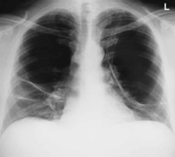
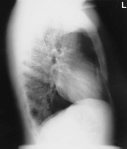
A minimum of two projections, taken at 90° or as near right angles from each other as possible, are essential in determining the location of any lesion or foreign body (Fig. 1-104).

Example

Foreign bodies (the density) embedded in tissues of the knee. Both AP/PA and lateral projections are necessary to determine the exact location of this “nail.”

3 Determination of alignment of fractures

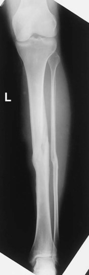
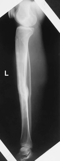
All fractures require a minimum of two projections, taken at 90° or as near right angles as possible, both to visualize fully the fracture site and to determine alignment of the fractured parts (Figs. 1-105 and 1-106).

image
Fig. 1-104 AP and lateral projection for foreign body (nail through anterior knee).
image
Fig. 1-105 AP projection for fracture alignment.
image
Fig. 1-106 Lateral projection for fracture alignment.

Chest

Routine

• PA, 90

• Lateral, 91

Upper Airway

Routine

• Lateral, 100

• AP, 101

Chest

Special

• AP supine or semierect, 94

• Lateral decubitus, 95

• AP lordotic, 96

• Anterior obliques, 97

• Posterior obliques, 99

Minimum of Three Projections When Joints Are in Area of Interest

This second general rule or principle suggests that all radiographic procedures of the skeletal system involving joints require a minimum of three projections rather than only two. These are AP or PA, lateral, and oblique projections.

The reason for this rule is that more information is needed than can be provided on only two projections. For example, with multiple surfaces and angles of the bones making up the joint, a small oblique chip fracture or other abnormality within the joint space may not be visualized on either frontal or lateral views but may be well demonstrated in the oblique position.

Following are examples of examinations that generally require three projections as routine (joint is in prime interest area):

• Fingers

• Toes

• Hand

• Wrist (Fig. 1-107)

• Elbow

• Ankle

• Foot

• Knee

Examples of examinations that require two projections as routine include the following:

• Forearm

• Humerus

• Femur

• Hips

• Tibia-fibula (Figs. 1-108 and 1-109)

• Chest

Exceptions to Rules

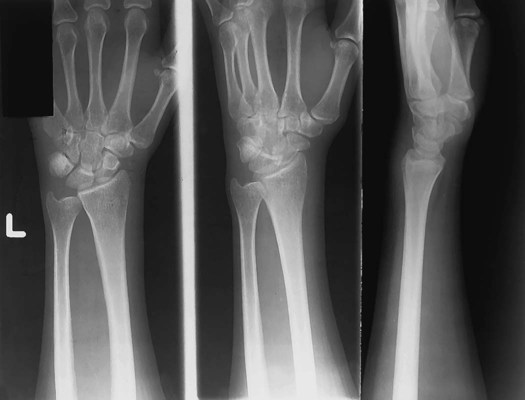
• Postreduction upper and lower limbs generally require only two projections for checking fracture alignment.

• A pelvis study requires only a single AP projection unless a hip injury is suspected.

image
Fig. 1-107 Wrist—requires three projections.
image
Fig. 1-108
image
Fig. 1-109 Lower leg—requires two projections and positions. Note: This is the same patient as in Figs. 1-105 and 1-106 on the preceding page, now demonstrating the healed fractures correctly aligned.

Palpation of Topographic Positioning Landmarks

Radiographic positioning requires the location of specific structures or organs within the body, many of which are not visible to the eye from the exterior. Therefore, the technologist must rely on bony landmarks to indicate their location. These bony structures are referred to as topographic landmarks. Fig. 1-110 shows examples of topographic landmarks of the pelvis. Topographic landmarks can be located by a process referred to as palpation.

Palpation

Palpation refers to the process of applying light pressure with the fingertips directly on the patient to locate positioning landmarks. This must be done gently because the area being palpated may be painful or sensitive for the patient. Also, the patient should always be informed of the purpose of this palpation before this process is begun, and patient permission should be obtained.

NOTE: Palpation of certain of these landmarks, such as the ischial tuberosity or the symphysis pubis, may be embarrassing for the patient and may not be permitted by institutional policy. Technologists should use other related landmarks as described in later chapters.

Viewing Radiographic Images

The manner in which PA and AP projection radiographic images are placed for viewing depends on the radiologist's preference and the most common practice in that part of the United States. However, in the United States and Canada, a common and accepted way to place radiographic images for viewing is to display them so that the patient is facing the viewer, with the patient in the anatomic position. This always places the patient's left to the viewer's right. This is true for either AP or PA projections.

Lateral positions are marked R or L by the side of the patient closest to the IR. Placement of lateral radiographic images for viewing varies depending on the radiologist's preference. One common method is to place the image so that the viewer is seeing the image from the same perspective as the x-ray tube. If the left marker is placed anteriorly to the patient, the L would be on the viewer's right (Fig. 1-114). However, some radiologists prefer to view laterals turned 90° and with the anteriorly placed L marker on the viewer's left. Technologists should determine the preferred method for viewing laterals in their department.

PA or AP oblique projections are placed for viewing the same way that a PA or AP projection is placed, with the patient's right to the viewer's left.

Decubitus chest and abdomen projections are generally viewed the way the x-ray tube “sees” them, placed crosswise with the upside of the patient also on the upper part of the view box (Fig. 1-114).

Upper and lower limb projections are viewed as projected by the x-ray beam onto the IR; the R or L lead marker appears right-side-up if it has been placed on the IR correctly.

Images that include the digits (hands and feet) generally are placed with the digits up. However, other images of the limbs are viewed in the anatomic position with the limbs hanging down (Fig. 1-116).

Viewing CT or MRI Images

The generally accepted way of viewing all CT and MRI axial images is similar to that used for conventional radiographs, even though the image represents a thin “slice” or sectional view of anatomic structures. In general, these images are placed so the patient's right is to the viewer's left (Fig. 1-117).

image
Fig. 1-110 Topographic landmarks of the pelvis.
image
Fig. 1-111 Viewing chest radiographs (patient's right always to viewer's left, both PA and AP).
image
Fig. 1-112 PA chest. (L appears reversed).
image
Fig. 1-113 AP chest. (L appears right-side-up).
image
Fig. 1-114 Left lateral decubitus chest.
image
Fig. 1-115 Left lateral chest.
image
Fig. 1-116 Viewing upper or lower limb radiographs (hands and feet, digits up).
image
Fig. 1-117 Axial (cross-sectional) image (upper thorax—level of T3) (patient's right to viewer's left).

Resources (Part One)

ARRT 2012 content specifications for the examination in radiography, attachment B, August 2010.

American Registry of Radiologic Technologists code of ethics, August 1, 2010.

Drake, R, Vogl, W, Mitchell, A. Gray's anatomy for students, ed 2. Philadelphia: Churchill Livingstone; 2010.

Part Two: Imaging Principles

Image Quality in Film-Screen (Analog) Radiography

Since the discovery of x-rays in 1895, methods of acquiring and storing x-ray images have evolved. Conventional film-screen technology with the associated chemical processing and film libraries is being replaced rapidly by digital technology. Digital technology uses computers and x-ray receptors to acquire and process images; specialized digital communication networks are used to transmit and store the x-ray images.

This period of technologic transition necessitates that students have an understanding of all image acquisition technologies because they will find themselves working in imaging departments that acquire images by using only digital technology, only film-screen technology, or a combination of both.

This part provides an introduction to radiographic technique and image quality for both film-screen imaging and digital imaging. The study of radiographic technique and image quality includes factors that determine the accuracy with which structures that are being imaged are reproduced in the image. Each of these factors has a specific effect on the final image, and the technologist must strive to maximize these factors to produce the best image possible at the lowest achievable dose.

This part also describes methods of digital image acquisition, discusses the application of digital imaging, and provides an introduction to the important principles of radiation safety.

Analog Images

Analog (film) images provide a two-dimensional image of anatomic structures. The image acquisition device is a film-screen system that consists of a pair of intensifying screens with a film between them. The screens and film are housed in an x-ray cassette that protects the film from light and ensures that screens are in close contact with the film. When screens receive the remnant radiation from the patient, they fluoresce; this light exposes the film, which must be chemically processed so the image can be viewed. Chemical processing includes several steps (developing, fixing, washing, and drying) and typically takes 60 to 90 seconds.

The film image (radiograph), which actually is composed of a deposit of metallic silver on a polyester base, is permanent; it cannot be altered. The various shades of gray displayed on the image are representative of the densities and atomic numbers of the tissues being examined. The film image is often referred to as a hard-copy image.

Analog image receptors are best described as self-regulating systems with a limited dynamic range. Analog image receptors are also described using the term exposure latitude. Exposure latitude is the range of exposure over which a film produces an acceptable image. An image produced with a level of exposure outside of the exposure latitude is an unacceptable image. Figs. 1-118 and 1-119 illustrate the dynamic range and exposure latitude of an analog IR. Note the impact of doubling the mAs on the diagnostic quality of the images of the elbow. Analog images have relatively narrow exposure latitude.

Exposure Factors for Analog (Film-Screen) Imaging

For each radiographic image obtained, the radiographer must select exposure factors on the control panel of the imaging equipment. The exposure factors required for each examination are determined by numerous variables, including the density/atomic number and thickness of the anatomic part, any pathology present, and image acquisition technology.

Exposure factors, sometimes referred to as technique factors, include the following:

• Kilovoltage (kV)—controls the energy (penetrating power) of the x-ray beam

• Milliamperage (mA)—controls the quantity or number of x-rays produced

• Exposure time (ms)—controls the duration of the exposure, usually expressed in milliseconds

Each of these exposure factors has a specific effect on the quality of the radiographic image. When performing radiographic procedures, technologists must apply their knowledge of exposure factors and imaging principles to ensure that images obtained are of the highest quality possible, while exposing patients to the lowest radiation dose possible.

image
Fig. 1-118 Analog dynamic range.

image
Fig. 1-119 Analog exposure latitude.

Image Quality Factors

Film-based radiographic images are evaluated on the basis of four quality factors. These four primary image quality factors are:

• Density

• Contrast

• Spatial resolution

• Distortion

Each of these factors has specific parameters by which it is controlled.

Density

Definition

Radiographic film density is defined as the amount of “blackness” on the processed radiograph. When a radiograph with high density is viewed, less light is transmitted through the image.

Controlling Factors

The primary controlling factor of film density is mAs. mAs controls density by controlling the quantity of x-rays emitted from the x-ray tube and the duration of the exposure. The relationship for our purpose can be described as linear; doubling the mAs doubles the quantity or duration of x-rays emitted, thus doubling the density on the film.

The distance of the x-ray source from the IR, or the source image receptor distance (SID), also has an effect on radiographic density according to the inverse square law. If the SID is doubled, at the IR, the intensity of the x-ray beam is reduced to one-fourth, which then reduces radiographic density to one-fourth. A standard SID generally is used to reduce this variable.

Other factors that influence the density on a film image include kV, part thickness, chemical development time/temperature, grid ratio, and film-screen speed.

Adjusting Analog Image Density

When film images (made with manual technique settings) are underexposed or overexposed, a general rule states that a minimum change in mAs of 25% to 30% is required to make a visible difference in radiographic density on the repeat radiograph. Some incorrectly exposed images may require a greater change, frequently 50% to 100%, or sometimes even greater. The radiograph of the hand obtained with the use of 2 mAs shown in Fig. 1-121 was underexposed; the repeat radiograph was obtained with the use of 4 mAs (Fig. 1-122). Doubling the mAs in this example resulted in doubling of the density on the radiograph. kV should not require an adjustment, provided that the optimal kV for the part thickness was used. SID also should not require adjustment; it is a constant.

image
Fig. 1-120 kV, mA, and mAs factors.
image
Fig. 1-121 2 mAs (60 kV)—underexposed.
image
Fig. 1-122 4 mAs (60 kV)—repeated, double mAs.
Density and Anode Heel Effect

The intensity of radiation emitted from the cathode end of the x-ray tube is greater than that emitted at the anode end; this phenomenon is known as the anode heel effect. Greater attenuation or absorption of x-rays occurs at the anode end because of the angle of the anode; x-rays emitted from deeper within the anode must travel through more anode material before exiting; thus, they are attenuated more.

Studies show that the difference in intensity from the cathode to the anode end of the x-ray field when a 17-inch (43-cm) IR is used at 40-inch (102-cm) SID can vary by 45%, depending on the anode angle* (Fig. 1-123). The anode heel effect is more pronounced when a short SID and a large field size are used.

Applying the anode heel effect to clinical practice assists the technologist in obtaining quality images of body parts that exhibit significant variation in thickness along the longitudinal axis of the x-ray field. The patient should be positioned so that the thicker portion of the part is at the cathode end of the x-ray tube and the thinner part is under the anode (the cathode and anode ends of the x-ray tube usually are marked on the protective housing). The abdomen, thoracic spine, and long bones of the limbs (e.g., the femur and tibia/fibula) are examples of structures that vary enough in thickness to warrant correct use of the anode heel effect.

A summary chart of body parts and projections for which the anode heel effect can be applied is provided; this information is also noted in the positioning pages for each of these projections throughout the text. In practice, the most common application of the anode heel effect is for anteroposterior (AP) projections of the thoracic spine.

It may not always be practical or even possible to take advantage of the anode heel effect; this depends on the patient's condition or the arrangement of specific x-ray equipment within a room.

image
Fig. 1-123 Anode heel effect.

SUMMARY OF ANODE HEEL EFFECT APPLICATIONS

PROJECTION ANODE END CATHODE END
Thoracic spine    
AP Head Feet
Femur    
AP and lateral (Fig. 1-123) Feet Head
Humerus    
AP and lateral Elbow Shoulder
Leg (tibia/fibula)    
AP and lateral Ankle Knee
Forearm    
AP and lateral Wrist Elbow
Compensating Filters

As was discussed in the previous section, body parts of varying anatomic density may result in an image that is partially overexposed or underexposed because the anatomic parts attenuate the beam differently. This problem can be overcome through the use of compensating filters, which filter out a portion of the primary beam toward the thin or less dense part of the body that is being imaged. Several types of compensating filters are in use; most are made of aluminum; however, some include plastic as well. The type of compensating filter used by the technologist depends on the clinical application (Fig. 1-125).

Compensating filters in common use include the following:

• Wedge filter (Fig. 1-124, A): Mounts on the collimator; the thicker portion of the wedge is placed toward the least dense part of the anatomy to even out the densities. This filter has numerous applications; the most common include AP foot, AP thoracic spine, and axiolateral projection of the hip.

• Trough filter: Mounts on the collimator and is used for chest imaging. The thicker peripheral portions of the filter are placed to correspond to the anatomically less dense lungs; the thinner portion of the filter corresponds to the mediastinum.

• Boomerang filter (Fig. 1-124, B): Is placed behind the patient and is used primarily for shoulder and upper thoracic spine radiography, where it provides improved visualization of soft tissues on the superior aspect of the shoulder and upper thoracic spine.

Summary of Density Factors

Adequate density, as primarily controlled by mAs, must be visible on processed film if the structures being radiographed are to be accurately represented. Too little density (underexposed) or too much density (overexposed) does not adequately demonstrate the required structures. Correct use of the anode heel effect and compensating filters helps to demonstrate optimal film density on anatomic parts that vary significantly in thickness.

image
Fig. 1-124 Wedge (A) and boomerang (B) compensating filters (for use for upper thoracic spine and lateral hip projections). (Courtesy Ferlic Filters, Ferlic Filter Co, LLC.)
image
Fig. 1-125 Radiographic applications of compensating filters—hip (A) and upper thoracic spine (B). (Courtesy Ferlic Filters, Ferlic Filter Co, LLC.)

Contrast

Definition

Radiographic contrast is defined as the difference in density between adjacent areas of a radiographic image. When the density difference is large, the contrast is high and when the density difference is small, the contrast is low. This is demonstrated by the step wedge and by the chest radiograph in Fig. 1-126, which shows greater differences in density between adjacent areas; thus, this would be high contrast. Fig. 1-127 shows low contrast with less difference in density on adjacent areas of the step wedge and the associated radiograph.

Contrast can be described as long-scale or short-scale contrast, referring to the total range of optical densities from the lightest to the darkest part of the radiographic image. This is also demonstrated in Fig. 1-126, which shows short-scale/high-contrast (greater differences in adjacent densities and fewer visible density steps), compared with Fig. 1-127, which illustrates long-scale/low-contrast.

Contrast allows the anatomic detail on a radiographic image to be visualized. Optimum radiographic contrast is important, and an understanding of contrast is essential for evaluating image quality.

Low or high contrast is not good or bad by itself. For example, low contrast (long-scale contrast) is desirable on radiographic images of the chest. Many shades of gray are required for visualization of fine lung markings, as is illustrated by the two chest radiographs in Figs. 1-126 and 1-127. The low-contrast (long-scale contrast) image in Fig. 1-127 reveals more shades of gray, as evident by the faint outlines of vertebrae that are visible through the heart and the mediastinal structures. The shades of gray that outline the vertebrae are less visible through the heart and the mediastinum on the high-contrast chest radiograph shown in Fig. 1-126.

Controlling Factors

The primary controlling factor for contrast in film-based imaging is kilovoltage (kV). kV controls the energy or penetrating power of the primary x-ray beam. The higher the kV, the greater is the energy, and the more uniformly the x-ray beam penetrates the various mass densities of all tissues. Therefore, higher kV produces less variation in attenuation (differential absorption), resulting in lower contrast.

kV is also a secondary controlling factor of density. Higher kV, resulting in both more numerous x-rays and greater energy x-rays, causes more x-ray energy to reach the IR, with a corresponding increase in overall density. A general rule of thumb states that a 15% increase in kV will increase film density, similar to doubling the mAs. In the lower kV range, such as 50 to 70 kV, an 8- to 10-kV increase would double the density (equivalent to doubling the mAs). In the 80- to 100-kV range, a 12- to 15-kV increase is required to double the density. The importance of this relates to radiation protection because as kV is increased, mAs can be significantly reduced, resulting in absorption of less radiation by the patient.

Other factors may affect radiographic contrast. The amount of scatter radiation the film-screen receives influences the radiographic contrast. Scatter radiation is radiation that has been changed in direction and intensity as a result of interaction with patient tissue. The amount of scatter produced depends on the intensity of the x-ray beam, the amount of tissue irradiated, and the type and thickness of the tissue. Close collimation of the x-ray field reduces the amount of tissue irradiated, reducing the amount of scatter produced and increasing contrast. Close collimation also reduces the radiation dose to the patient and the technologist.

Irradiation of thick body parts produces a considerable amount of scatter radiation, which decreases image contrast. A device called a grid is used to absorb much of the scatter radiation before it hits the IR.

image
Fig. 1-126 High-contrast, short-scale 50 kV, 800 mAs.
image
Fig. 1-127 Low-contrast, long-scale 110 kV, 10 mAs.
Grids

Because the amount of scatter increases with the thickness of the tissue irradiated, it generally is recommended that a grid should be used for radiography of any body part that is thicker than 10 cm. Depending on the examination, the grid may be portable or may be built into the x-ray equipment. It is positioned between the patient and the IR and absorbs much of the scatter radiation before it hits the IR. Absorption of scatter is a key event that increases image contrast.

Correct Use of Grids

An in-depth discussion of grid construction and characteristics is beyond the scope of this text. However, several rules must be followed to ensure optimal image quality when grids are used. Incorrect use of grids results in loss of optical density across all or part of the radiographic image; this feature is called grid cutoff. Grid cutoff occurs in various degrees and has several causes. Causes of grid cutoff include the following:

1. Off-center grid

2. Off-level grid

3. Off-focus grid

4. Upside-down grid

1 Off-center grid

The CR must be centered along the center axis of the grid. If it is not, lateral decentering is said to occur. The more the CR is off center from the centerline of the grid, the greater is the cutoff that results.

In certain clinical situations in which it is difficult to position the area of interest in the center of the grid, the grid may have to be turned so that the lead strips run perpendicular to the length of the patient to allow accurate centering (e.g., horizontal beam lateral lumbar spine).

Exception: Decubitus—short dimension (SD)—type linear grids:

An exception to the more common lengthwise focused grid with the lead strips and center axis running lengthwise with the grid is the decubitus-type crosswise linear grid. This grid, in which the lead strips and center axis are running crosswise along the shorter dimension of the grid, is useful for horizontal beam decubitus-type projections. For these projections, the grid is placed lengthwise with the patient, but the CR is centered along the crosswise axis of the grid to prevent grid cutoff.

2 Off-level grid

With angling, the CR must be angled along the long axis of the lead strips. Angling across the grid lines results in grid cutoff. Off-level grid cutoff also occurs if the grid is tilted; the CR hits the lead lines at an angle (Fig. 1-129).

3 Off-focus grid

A focused grid must be used at a specified SID if grid cutoff is to be prevented. Grids typically have a minimum and a maximum usable SID; this is called the focal range. The focal range is determined by the grid frequency (number of grid strips per inch or centimeter) and the grid ratio (height of lead strips compared with the space between them). Portable grids generally have a lower grid frequency and a lower grid ratio than fixed grids or Bucky-type grids. A common grid ratio for portable grids is 6 : 1 or 8 : 1 compared with 12 : 1 for Bucky grids. This indicates a greater focal range for portable grids, but SID limitations still exist to prevent grid cutoff (Fig. 1-130). Each technologist should know which types of portable grids are available and should know the focal range of each.

image
Fig. 1-128 Off-center grid cutoff.
image
Fig. 1-129 Off-level grid cutoff.
image
Fig. 1-130 Off-focus grid cutoff.

4 Upside-down focused grid

Each grid is labeled to indicate the side that must be positioned to face the x-ray tube. The lead strips are tilted or focused to allow the x-ray beam to pass through unimpeded (if the SID is within the focal range and the grid is correctly placed). If the grid is positioned upside-down, the image will show severe cutoff (Fig. 1-131).

Summary of Contrast Factors

Selection of the appropriate kV is a balance between optimal image contrast and lowest possible patient dose. A general rule states that the highest kV and the lowest mAs that yield sufficient diagnostic information should be used on each radiographic examination.* Close collimation and correct use of grids also ensure that the processed radiographic image displays optimal contrast.

Spatial Resolution

Spatial resolution is defined as the recorded sharpness of structures on the image. Resolution on a radiographic image is demonstrated by the clarity or sharpness of fine structural lines and borders of tissues or structures on the image. Resolution is also known as detail, recorded detail, image sharpness, or definition. Resolution of film-screen images generally is measured and expressed as line pairs per millimeter (lp/mm), in which a line pair is seen as a single line and an interspace of equal width. The higher the line pair measure, the greater is the resolution; it is typically 5 to 6 lp/mm for general imaging. Lack of visible sharpness or resolution is known as blur or unsharpness.

Controlling Factors

The optimal radiograph displays a sharp image, as listed under “Evaluation Criteria” for each position in this text. Resolution with film-screen imaging is controlled by geometric factors, the film-screen system, and motion.

Geometric Factors

Geometric factors that control or influence resolution consist of focal spot size, SID, and object image receptor distance (OID). The effect of OID is explained and illustrated in Fig. 1-137.

The use of the small focal spot results in less geometric unsharpness (see Fig. 1-132). To illustrate, a point source is used commonly as the source of x-rays in the x-ray tube; however, the actual source of x-rays is an area on the anode known as the focal spot. Most x-ray tubes exhibit dual focus; that is, they have two focal spots: large and small. Use of the small focal spot results in less unsharpness of the image, or an image with a decreased penumbra. A penumbra refers to the unsharp edges of objects in the projected image. However, even with the use of the small focal spot, some penumbra is present.

Film-Screen System

With film-screen imaging systems, the film-screen speed used for an examination affects the detail shown on the resultant film. A faster film-screen system allows shorter exposure times, which are helpful in preventing patient motion and reducing dose; however, the image is less sharp than when a slower system is used.

image
Fig. 1-131 Upside-down grid cutoff.
image
Fig. 1-132 Effect of focal spot size.
Motion

The greatest deterrent to image sharpness as related to positioning is motion. Two types of motion influence radiographic detail: voluntary and involuntary.

Voluntary motion is that which the patient can control. Motion from breathing or movement of body parts during exposure can be prevented or at least minimized by controlled breathing and patient immobilization. Support blocks, sandbags, or other immobilization devices can be used to reduce motion effectively. These devices are most effective for examination of upper or lower limbs, as will be demonstrated throughout this text.

Involuntary motion cannot be controlled by the patient at will. Therefore, involuntary motion, such as peristaltic action of abdominal organs, tremors, or chills, is more difficult, if not impossible, to control.

If motion unsharpness is apparent on the image, the technologist must determine whether this blurring or unsharpness is due to voluntary or involuntary motion. This determination is important because these two types of motion can be controlled in various ways.

Difference between voluntary and involuntary motion

Voluntary motion is visualized as generalized blurring of linked structures, such as blurring of the thoracic bony and soft tissue structures as evident in Fig. 1-133. Voluntary motion can be minimized through the use of high mA and short exposure times. Increased patient cooperation is another factor that may contribute to decreased voluntary motion; a thorough explanation of the procedure and clear breathing instructions may prove helpful.

Involuntary motion is identified by localized unsharpness or blurring. This type of motion is less obvious but can be visualized on abdominal images as localized blurring of the edges of the bowel, with other bowel outlines appearing sharp (gas in the bowel appears as dark areas). Study Fig. 1-134 carefully to see this slight blurring in the left upper abdomen, indicated by arrows. The remaining edges of the bowel throughout the abdomen appear sharp. Fig. 1-133, by comparison, demonstrates overall blurring of the heart, ribs, and diaphragm. A clear explanation of the procedure by the technologist may aid in reducing voluntary motion; however, a decrease in exposure time with an associated increase in mA is the best and sometimes the only way to minimize motion unsharpness caused by involuntary motion.

Summary of Spatial Resolution Factors

Use of a small focal spot, an increase in SID, and a decrease in OID result in less geometric unsharpness and increased resolution. Patient motion also affects image quality; short exposure times and increased patient cooperation help to minimize voluntary motion unsharpness. Involuntary motion unsharpness is controlled only by short exposure times.

image
Fig. 1-133 Voluntary motion (breathing and body motion)—blurring of entire chest and overall unsharpness.
image
Fig. 1-134 Involuntary motion (from peristaltic action)—localized blurring in upper left abdomen (arrows).

Distortion

The fourth and final image quality factor is distortion, which is defined as the misrepresentation of object size or shape as projected onto radiographic recording media. Two types of distortion have been identified: size distortion (magnification) and shape distortion.

No radiographic image reproduces the exact size of the body part that is being radiographed. This is impossible to do because a degree of magnification or distortion or both always exists as a result of OID and divergence of the x-ray beam. Nevertheless, distortion can be minimized and controlled if some basic principles are used as a guide.

X-ray Beam Divergence

X-ray beam divergence is a basic but important concept in the study of radiographic positioning. It occurs because x-rays originate from a small source in the x-ray tube (the focal spot) and diverge as they travel to the IR (Fig. 1-135). The field size of the x-ray beam is limited by a collimator that consists of adjustable lead attenuators or shutters. The collimator and shutters absorb the x-rays on the periphery, controlling the size of the x-ray beam.

The center point of the x-ray beam, which is called the central ray (CR), theoretically has no divergence; the least amount of distortion is seen at this point on the image. All other aspects of the x-ray beam strike the IR at some angle, with the angle of divergence increasing to the outermost portions of the x-ray beam. The potential for distortion at these outer margins is increased.

Fig. 1-135 demonstrates three points on a body part (marked A, B, and C) as projected onto the IR. Greater magnification is demonstrated at the periphery (A and B) than at the point of the central ray (C). Because of the effect of the divergent x-ray beam, combined with at least some OID, this type of size distortion is inevitable. It is important for technologists to control closely and minimize distortion as much as possible.

Controlling Factors

Following are four primary controlling factors of distortion:

1. Source image receptor distance (SID)

2. Object image receptor distance (OID)

3. Object image receptor alignment

4. Central ray alignment/centering

1 SID

The first controlling factor for distortion is SID. The effect of SID on size distortion (magnification) is demonstrated in Fig. 1-136. Note that less magnification occurs at a greater SID than at a shorter SID. This is the reason that chest radiographs are obtained at a minimum SID of 72 inches (183 cm) rather than of 40 to 48 inches (102 to 122 cm), which is commonly used for most other examinations. A 72-inch (183-cm) SID results in less magnification of the heart and other structures within the thorax.

image
Fig. 1-135 X-ray beam divergence.
image
Fig. 1-136 Effect of SID.

Minimum 40-Inch (or 102-Cm) SID

It has been a long-standing common practice to use 40 inches (rounded to 102 cm) as the standard SID for most skeletal radiographic examinations. However, in the interest of improving image resolution by decreasing magnification and distortion, it is becoming more common to increase the standard SID to 44 inches or 48 inches (112 cm or 122 cm). Additionally, it has been shown that increasing the SID from 40 to 48 inches reduces the entrance or skin dose even when the requirement for increased mAs is considered. In this textbook, the suggested SID listed on each skeletal positioning page is a minimum of 40 inches, with 44 inches or 48 inches recommended if the equipment and departmental protocol allow.

2 OID

The second controlling factor for distortion is OID. The effect of OID on magnification or size distortion is illustrated clearly in Fig. 1-137. The closer the object being radiographed is to the IR, the less are the magnification and shape distortion and the better is the resolution.

3 Object image receptor alignment

A third important controlling factor of distortion is object IR alignment. This refers to the alignment or plane of the object that is being radiographed in relation to the plane of the image receptor. If the object plane is not parallel to the plane of the IR, distortion occurs. The greater the angle of inclination of the object or the IR, the greater is the amount of distortion. For example, if a finger being radiographed is not parallel to the IR, the interphalangeal joint spaces will not be open because of the overlapping of bones, as is demonstrated in Fig. 1-138.

image
Fig. 1-137 Effect of OID.
image
Fig. 1-138 Object alignment and distortion.

Effect of improper object IR alignment

In Fig. 1-139, the digits (fingers) are supported and aligned parallel to the image receptor, resulting in open interphalangeal joints and undistorted phalanges.

In Fig. 1-140, in which the digits are not parallel to the IR, the interphalangeal joints of the digits are not open, and possible pathology within these joint regions may not be visible. Note the open joints of the digits in Fig. 1-141 compared with Fig. 1-142 (see arrows). Additionally, the phalanges will be either foreshortened or elongated.

These examples demonstrate the important principle of correct object IR alignment. The plane of the body part that is being imaged must be as near parallel to the plane of the IR as possible to produce an image of minimal distortion.

4 Central ray alignment

The fourth and final controlling factor for distortion is central ray alignment (centering), an important principle in positioning. As was previously stated, only the center of the x-ray beam, the CR, has no divergence because it projects that part of the object at 90°, or perpendicular to the plane of the IR (refer to Fig. 1-135). Therefore, the least possible distortion occurs at the CR. Distortion increases as the angle of divergence increases from the center of the x-ray beam to the outer edges. For this reason, correct centering or correct central ray alignment and placement is important in minimizing image distortion.

Examples of correct CR placement for an AP knee are shown in Figs. 1-143 and 1-145. The CR passes through the knee joint space with minimal distortion, and the joint space should appear open.

Fig. 1-144 demonstrates correct centering for an AP distal femur, in which the CR is correctly directed perpendicular to the IR and centered to the mid distal femur. However, the knee joint is now exposed to divergent rays (as shown by the arrow), and this causes the knee joint to appear closed (Fig. 1-146).

CR angle

For most projections, the CR is aligned perpendicular, or 90°, to the plane of the IR. For certain body parts, however, a specific angle of the CR is required, as is indicated by the positioning descriptions in this text as the CR angle. This means that the CR is angled from the vertical in a cephalic or caudad direction so as to use distortion intentionally without superimposing anatomic structures.

Summary of Factors That May Affect Distortion

Use of the correct SID while minimizing OID, ensuring that the object and IR are aligned, and correctly aligning or centering the CR to the part can minimize distortion on a radiographic image.

image
Fig. 1-139 Digits parallel to IR—joints open.
image
Fig. 1-140 Digits not parallel to IR—joints not open.
image
Fig. 1-141 Digits parallel—joints open.
image
Fig. 1-142 Digits not parallel—joints not open.
image
Fig. 1-143 Correct CR centering for AP knee.
image
Fig. 1-144 Correct CR centering for AP femur (distortion occurs at knee).
image
Fig. 1-145 Correct CR centering for knee.
image
Fig. 1-146 Incorrect CR centering for knee.

SUMMARY OF IMAGE QUALITY AND PRIMARY CONTROLLING FACTORS

QUALITY FACTOR PRIMARY CONTROLLING FACTORS
1. Density mAs (mA and time)
2. Contrast kV
3. Spatial resolution Geometric factors
  Focal spot size
  SID
  OID
  Motion (voluntary and involuntary)
  Film-screen speed
4. Distortion SID
  OID
  Object IR alignment
  CR alignment or centering

Image Quality in Digital Radiography

Digital imaging in radiologic technology involves application of the analog-to-digital conversion theory and computer software and hardware. Although digital imaging differs from film-screen imaging in terms of the method of image acquisition, factors that may affect x-ray production, attenuation, and geometry of the x-ray beam still apply. This section provides a brief practical introduction to a very complex topic.

Digital Images

Digital radiographic images also provide a two-dimensional image of anatomic structures; however, they are viewed on a computer monitor and are referred to as soft-copy images. These images are a numeric representation of the x-ray intensities that are transmitted through the patient. Each digital image is two-dimensional and is formed by a matrix of picture elements called pixels (see Fig. 1-147). In diagnostic imaging, each pixel represents the smallest unit in the image; columns and rows of pixels make up the matrix. For illustrative purposes, consider a sheet of graph paper. The series of squares on the sheet can be compared with the matrix, and each individual square can be compared with a pixel.

Digital imaging requires the use of computer hardware and software applications to view images (Fig. 1-148), whereas film-based images use chemical processing to visualize anatomic structures. Digital processing involves the systematic application of highly complex mathematical formulas called algorithms. Numerous mathematical manipulations are performed on image data to enhance image appearance and to optimize quality. Algorithms are applied by the computer to every data set obtained before the technologist sees the image.

Digital imaging systems are capable of producing a radiographic image across a large range of exposure values and are described as having a wide dynamic range. Because of this wide dynamic range, it is essential that an institution define the exposure latitude for the digital imaging systems within its department. The exposure latitude for a digital imaging system is defined as the acceptable level of exposure that produces the desired image quality for the department. Fig. 1-150 demonstrates the dynamic range and exposure latitude of a digital imaging system. Note the increase from 1 to 8 mAs still produces a diagnostic image of the elbow.

Exposure Factors for Digital Imaging

Although kV and mA and time (mAs) must be selected if radiographic images are to be digitally acquired (Fig. 1-148), they do not have the same direct effect on image quality as they do in film-screen imaging. It must be remembered, however, that the kV and mAs used for the exposure affect patient dose.

mA controls the number of x-rays produced, and mAs (mA × time = mAs) refers to the number of x-rays and the duration of exposure. kV controls the penetrating power of the x-rays with all radiographic imaging (digital and film-screen systems). The kV selected must be adequate to penetrate the anatomy of interest. As kV increases, beam penetrability increases. A benefit of using a higher kV is that patient dose is reduced as compared with lower kV ranges. Compared with film-screen imaging, changes in kV can have less of a direct effect on final digital image contrast because the resultant contrast is also a function of the digital processing.

image
Fig. 1-147 Two-dimensional matrix display—pixel.
image
Fig. 1-148 Processing digital image.
image
Fig. 1-149 Digital imaging systems.
image
Fig. 1-150 Digital exposure latitudes. A, Option 1. B, Option 2.

Image Quality Factors

The factors used to evaluate digital image quality include the following:

• Brightness

• Contrast resolution

• Spatial resolution

• Distortion

• Exposure indicator

• Noise

Brightness

Brightness is defined as the intensity of light that represents the individual pixels in the image on the monitor. In digital imaging, the term brightness replaces the film-based term density (Figs. 1-151 and 1-152).

Controlling Factors

Digital imaging systems are designed to display electronically the optimal image brightness under a wide range of exposure factors. Brightness is controlled by the processing software through the application of predetermined digital processing algorithms. In contrast to the linear relationship between mAs and density in film-screen imaging, changes in mAs do not have a controlling effect on digital image brightness. Although the density of a film image cannot be altered once it is exposed and chemically processed, the user can adjust the brightness of the digital image after exposure (see section on Post-Processing later in this chapter).

Contrast Resolution

In digital imaging, contrast is defined as the difference in brightness between light and dark areas of an image. This definition is similar to the definition used in film-based imaging, where contrast is the difference in density of adjacent areas on the film (see Figs. 1-153 and 1-154, which show several examples of different contrast images). Contrast resolution refers to the ability of an imaging system to distinguish between similar tissues.

Controlling Factors

Digital imaging systems are designed to display electronically optimal image contrast under a wide range of exposure factors. Radiographic contrast is affected by the digital processing computer through the application of predetermined algorithms, in contrast to film-screen imaging, in which kV is the controlling factor for image contrast. Although the contrast of a film image cannot be altered after exposure and processing, the user can manipulate the contrast of the digital image (see later section on Post-Processing).

Pixels and bit depth

Each pixel in an image matrix demonstrates a single shade of gray when viewed on a monitor; this is representative of the physical properties of the anatomic structure. The range of possible shades of gray demonstrated is related to the bit depth of the pixel, which is determined by the manufacturer. Although a comprehensive description of bit depth is beyond the scope of this text, it is important to note that the greater the bit depth of a system, the greater is the contrast resolution (i.e., the greater is the number of possible shades of gray that a pixel can have).

Because computer theory is based on the binary system, a 14-bit system, for example, is represented as 214; the 14-bit-deep pixel could represent any one of 16,384 possible shades of gray, from black to white. Bit depth is determined by the manufacturer's system design and is closely related to the imaging procedures for which the equipment is designed. The most common bit depths available are 10, 12, and 16. For example, a digital system for chest imaging should have a bit depth greater than 10 bits (210) if it is to capture all required information; the x-ray beam that exits a patient who is having a chest x-ray can have a range of more than 1024 intensities.

Pixel size

Two pixel sizes are used in medical imaging. These are acquisition pixel size, which is the minimum size that is inherent to the acquisition system, and display pixel size, which is the minimum pixel size that can be displayed by a monitor. A general radiography acquisition matrix may be 3000 × 3000 pixels—more than 9 million pixels (9 megapixels)—in a 17 × 17-inch (43 × 43-cm) image.

Scatter radiation control

Because digital receptors are more sensitive to low-energy radiation, controlling scatter radiation is an important factor in obtaining the appropriate image contrast. This is accomplished by the correct use of grids, by close collimation, and by selection of the optimal kV.

image
Fig. 1-151 AP shoulder—high brightness (light).
image
Fig. 1-152 AP shoulder—less brightness (dark).
image
Fig. 1-153 AP shoulder—higher contrast.
image
Fig. 1-154 AP shoulder—lower contrast.

Spatial Resolution

Spatial resolution in digital imaging is defined as the recorded sharpness or detail of structures on the image—the same as defined for film-screen imaging.

Resolution in a digital image represents a combination of the traditional factors explained previously for film-screen imaging (focal spot size, geometric factors, and motion) and, just as important, the acquisition pixel size. This pixel size is inherent to the digital imaging receptor. The smaller the acquisition pixel size, the greater the spatial resolution. Spatial resolution is measured in line pairs per millimeter. Current digital imaging systems employed for general radiography have spatial resolution capabilities ranging from approximately 2.5 lp/mm to 5.0 lp/mm.

Controlling Factors

In addition to acquisition pixel size, resolution is controlled by the display matrix. The perceived resolution of the image depends on the display capabilities of the monitor. Monitors with a larger display matrix can display images with higher resolution.

Distortion

Controlling Factors

Distortion is defined as the misrepresentation of object size or shape as projected onto radiographic recording media, just as for film-screen imaging. The factors that affect distortion (SID, OID, and CR alignment) are the same as for film-screen imaging and digital imaging. Refer to the first part of this chapter; minimizing distortion is an important image quality factor.

Exposure Indicator

The exposure indicator in digital imaging is a numeric value that is representative of the exposure that the IR has received. Depending on the manufacturer of the system, the exposure indicator may also be called the sensitivity (S) number.

Controlling Factors

The exposure indicator depends on the dose of the radiation that strikes the receptor. It is a value that is calculated from the effect of mAs, the kV, the total receptor area irradiated, and the objects exposed (e.g., air, metal implants, patient anatomy). Depending on the manufacturer and the technique used to calculate this value, the exposure indicator is displayed for each exposure.

An exposure indicator, as used by certain manufacturers, is inversely related to the radiation that strikes the receptor. For example, if the range for an acceptable image for certain examinations is 150 to 250, a value greater than 250 would indicate underexposure, and a value less than 150 would indicate overexposure.

An exposure indicator as used by other manufacturers is directly related to the radiation striking the IR, as determined by logarithmic calculations. For example, if an acceptable exposure indicator is typically 2.0 to 2.4, an indicator value less than 2.0 would indicate underexposure, whereas an indicator value greater than 2.4 would indicate overexposure.

This text uses the term exposure indicator when referring to this variable.

It has been stated previously that digital imaging systems are able to display images that have been obtained through the use of a wide range of exposure factors. Despite this wide dynamic range, there are limitations, and the technologist must ensure that the exposure factors used are acceptable and within the institution's defined exposure latitude (similar to reviewing a film image to confirm that adequate contrast and density are present). Checking the exposure indicator is key in verifying that acceptable quality digital radiographic images have been obtained with the least possible dose to the patient.

If the exposure indicator is outside the recommended range for the digital system, the image may still appear acceptable when viewed on the monitor of the technologist's workstation. The monitor the technologist uses to view the image typically provides lower resolution than is provided by the radiologist's reporting workstation. The technologist's workstation is intended to allow verification of positioning and general image quality; however, this image is typically not of diagnostic quality. The monitor of a radiologist's reporting workstation typically provides superior spatial and contrast resolution caused by an increased display matrix with smaller pixels and superior brightness characteristics.

image
Fig. 1-155 Low exposure indicator indicates underexposure with “noisy” undesirable image.
image
Fig. 1-156 Example of desirable exposure with acceptable exposure indicator.
image
Fig. 1-157 High exposure indicator indicates overexposure.

Noise

Noise is defined as a random disturbance that obscures or reduces clarity. In a radiographic image, this translates into a grainy or mottled appearance of the image.

Signal-to-Noise Ratio (SNR)

One way to describe noise in digital image acquisition is the concept of signal-to-noise ratio (SNR). The number of x-ray photons that strike the receptor (mAs) can be considered the “signal.” Other factors that negatively affect the final image are classified as “noise.” A high SNR is desirable in imaging, in which the signal (mAs) is greater than the noise, so that low-contrast soft tissue structures can be demonstrated. A low SNR is undesirable; a low signal (low mAs) with accompanying high noise obscures soft tissue detail and produces a grainy or mottled image.

High SNR

Although a high SNR is favorable (Fig. 1-158), technologists must ensure that exposure factors used are not beyond what is required for the projection so as not to overexpose the patient needlessly. Overexposed images are not readily evident with digital processing and display, so checking the exposure indicator as described on the previous page is the best way to determine this.

Low SNR

When insufficient mAs is selected for a projection, the receptor does not receive the appropriate number of x-ray photons, resulting in a low SNR and a noisy image (Fig. 1-159). This mottle may not be readily visible on the lower resolution monitor of the technologist's workstation, but the exposure indicator, as checked for each projection, can aid in determining this. The technologist may check for noise at the workstation by using the magnify feature and magnifying the image to determine the level of noise present within the image. In the event that noise is clearly visible in the image without any magnification, the image should be reviewed by the radiologist to determine if the image needs to be repeated.

Scatter radiation leads to a degradation of image contrast that can be controlled by the use of grids and correct collimation, as was described previously.

A secondary factor related to noise in a radiographic image is electronic noise. Although a comprehensive discussion of electronic noise is beyond the scope of this text, electronic noise typically results from inherent noise in the electronic system, nonuniformity of the image receptor, or power fluctuations.

image
Fig. 1-158 Good-quality image—acceptable SNR.
image
Fig. 1-159 Poor-quality image, “noisy” (grainy)—low SNR.

Post-Processing

One of the advantages of digital imaging technology over film-screen technology is the ability to post-process the image at the technologist's workstation. Post-processing refers to changing or enhancing the electronic image for the purpose of improving its diagnostic quality. In post-processing, algorithms are applied to the image to modify pixel values. Once viewed, the changes made may be saved, or the image default settings may be reapplied to enhance the diagnostic quality of the image. It is important to note the image that has been modified at the technologist's workstation and sent to PACS may not be unmodified by PACS. As a result of this inability of PACS to undo changes made at the technologist's workstation, post-processing of images at the technologist's workstation should be avoided.

Post-Processing and Exposure Indicator Range

After an acceptable exposure indicator range for the system has been determined, it is important to determine whether the image is inside or outside this range. If the exposure indicator is below this range (indicating low SNR), post-processing would not be effective in minimizing noise; more “signal” cannot be created through post-processing. Theoretically, if the algorithms are correct, the image should display with the optimal contrast and brightness. However, even if the algorithms used are correct and exposure factors are within an acceptable range, as indicated by the exposure indicator, certain post-processing options may still be applied for specific image effects.

Post-Processing Options

Various post-processing options are available in medical imaging (see Figs. 1-160 through 1-163). The most common of these options include the following:

Windowing: The user can adjust image contrast and brightness on the monitor. Two types of adjustment are possible: window width, which controls the contrast of the image (within a certain range), and window level, which controls the brightness of the image, also within a certain range.

Smoothing: Specific image processing is applied to reduce the display of noise in an image. The process of smoothing the image data does not eliminate the noise present in the image at the time of acquisition.

Magnification: All or part of an image can be magnified.

Edge enhancement: Specific image processing that alters pixel values in the image is applied to make the edges of structures appear more prominent compared with images with less or no edge enhancement. The spatial resolution of the image does not change when edge enhancement is applied.

Equalization: Specific image processing that alters the pixel values across the image is applied to present a more uniform image appearance. The pixel values representing low brightness are made brighter, and pixel values with high brightness are made to appear less bright.

Subtraction: Background anatomy can be removed to allow visualization of contrast media–filled vessels (used in angiography).

Image reversal: The dark and light pixel values of an image are reversed—the x-ray image reverses from a negative to a positive.

Annotation: Text may be added to images.

image
Fig. 1-160 Chest image with no post-processing options applied.
image
Fig. 1-161 Chest image with reversal option.
image
Fig. 1-162 Subtracted AP shoulder angiogram image.
image
Fig. 1-163 Subtracted and magnified option of shoulder angiogram.

Applications of Digital Technology

Although digital technology has been used for years in digital fluoroscopy and CT (further information on these modalities is available in Chapters 12 and 18), its widespread application to general imaging is relatively new. This section introduces and briefly describes the digital imaging technology used in general radiography. Each of the systems described start the imaging process using an x-ray beam that is captured and converted into a digital signal.

Digital Imaging Systems

The many acronyms associated with digital imaging have created a plethora of misconceptions regarding digital imaging systems, and these misconceptions have resulted in technologists not having a thorough understanding of how various digital imaging systems work. The following sections describe the current digital imaging systems based on how the image data are captured and data extracted and secondly by their appearance. Regardless of appearance and how the image data are captured and extracted, each of the digital imaging systems described has a wide dynamic range that requires a defined exposure latitude to enable the technologist to adhere to the principles of ALARA.

Photostimulable Storage Phosphor (PSP) Plate

PSP technology was the first widely implemented digital imaging system for general radiography. It is most commonly called computed radiography (CR); however it is addressed in this section as storage phosphor (PSP)–based digital systems. A PSP-based digital imaging system relies on the use of a storage phosphor plate that serves the purpose of capturing and storing the x-ray beam exiting the patient. The exposure of the plate to radiation results in the migration of electrons to electron traps within the phosphor material. The greater the exposure to the plate, the greater the number of electrons moved to the electron traps. The exposed plate containing the latent image undergoes a reading process following the exposure. The reading of the plate involves scanning of the entire plate from side to side using a laser beam. As the laser moves across the plate, the trapped electrons in the phosphor are released from the electron traps and migrate back to their resting location. The migration of the electrons back to their resting locations results in the emission of light from the phosphor. The greater the exposure to the plate, the greater the intensity of the light emitted from the plate during the reading process. The light released is collected by an optical system that sends the light to a device responsible for converting the light into an analog electrical signal. The device may be a photomultiplier tube or CCD. The analog electrical signal is sent to an analog-to-digital convertor (ADC) so that the image data may be processed by the computer to create the desired digital image. Depending on the manufacturer, the image may be viewed on the technologist's workstation 5 seconds after plate reading. After the reading process, the PSP plate is exposed to a bright light so that any remaining latent image is erased from the plate and the plate may be used for the next exposure.

A PSP-based digital imaging system may be cassette-based or cassette-less. A cassette-based system allows the technologist to place the IR physically in a variety of locations. The cassette-less system (Figs. 1-165 and 1-166) provides the technologist with a larger device that encloses the IR. The IR in a cassette-less system has a limited amount of movement to align with the x-ray beam and anatomic structure owing to its design. The appearance of the device is not an indication of what is happening inside of the device after exposure to the x-ray beam. Therefore, it is critical that technologists recognize and understand what is inside of the equipment with which they work.

Technologist Workstation

The workstation includes a bar-code reader (optional), a monitor for image display, and a keyboard with a mouse or trackball for entering commands for post-processing. The technologist verifies the patient position and checks the exposure indicator at this workstation.

Image Archiving

After the image quality has been verified and any needed adjustments have been made, the image can be transmitted to the digital archive for viewing and reading by the referring physician or radiologist. Images also may be printed onto film by a laser printer.

image
Fig. 1-164 PSP cassette and reader.
image
Fig. 1-165 Cassette-less imaging system.
image
Fig. 1-166 Cassette-less chest imaging system.

Application of PSP Digital Systems

Regardless of the technology used to acquire radiographic images, accurate positioning and attention to technical details are important. However, when digital technology is used, attention to these details becomes more important because of the following factors.

Collimation

In addition to the benefit of reducing radiation dose to the patient, collimation that is closely restricted to the part that is being examined is key to ensuring optimal image quality. The software processes the entire x-ray field as a data set; any unexpected attenuation of the beam may be included in the calculations for brightness, contrast, and exposure indicator. If the collimation is not closely restricted, the exposure indicator may be misrepresented, and the image may exhibit lower contrast.

Accurate Centering of Part and IR

Because of the way the extracted image data are analyzed, the body part and collimated exposure field should be centered to the IR to ensure proper image display. Failure to align the part to the receptor accurately and collimate the exposure field properly may result in poor image quality on initial image display.

Use of Lead Masks

Use of lead masks or a blocker for multiple images on a single IR is recommended when a cassette-based PSP system is used (Fig. 1-167). This recommendation is due to the hypersensitivity of the PSP plate to lower energy scatter radiation; even small amounts may affect the image. (Note: Some manufacturers recommend that only one image be centered and placed per IR. Check with your department to find out whether multiple images can be placed on a single IR.)

Use of Grids

Use of grids (as explained in an earlier section of this chapter) for body parts larger (thicker) than 10 cm is especially important when images are acquired with the use of PSP image receptors because of the hypersensitivity of the image plate phosphors to scatter radiation.

Exposure Factors

Because of their wide dynamic range, PSP-based systems are able to display an acceptable image from a broad range of exposure factors (kV, mAs). It is important to remember, however, that the ALARA principle (exposure to patient as low as reasonably achievable) must be followed, and the lowest exposure factors required to obtain a diagnostic image must be used. When the image is available for viewing, the technologist must check the exposure indicator to verify that the exposure factors used are consistent with the ALARA principle and diagnostic image quality. Increasing kV by 5 to 10, while decreasing mAs by the equivalent ratio with digital imaging equipment, maintains image quality, while significantly reducing entrance skin exposure dose to the patient.

Evaluation of Exposure Indicator

As soon as the image is available for viewing at the workstation, it is critiqued for positioning and exposure accuracy. The technologist must check the exposure indicator to verify that the exposure factors used were in the correct range for optimum quality with the lowest radiation dose to the patient.

image
Fig. 1-167 Lead blockers on cassette and close collimation are important with the use of analog (film-based) cassettes.

Flat Panel Detector with Thin Film Transistor (FPD-TFT)

The flat panel detector with thin film transistor (FPD-TFT) digital imaging system for general radiography is a second type of digital imaging system. The FPD-TFT system is commonly referred to as digital radiography (DR) or direct digital radiography (DDR); however, in this section, the systems are referred to as FPD-TFT systems.

The FPD-TFT IR may be constructed using amorphous selenium or amorphous silicon. The purpose of those two materials is to provide a source of electrons to the TFT. The creation of the electrons for the TFT is different with the two materials. The exposure of amorphous selenium to x-ray photons results in the movement of electrons through the material and into the electron collection portion of the TFT. Amorphous silicon requires the use of a scintillator, which produces light when struck by x-ray photons. The light exiting the scintillator causes the movement of electrons through the amorphous silicon and into the electron collection centers of the TFT. The TFT serves the purpose of collecting the electrons in an ordered manner and then sending the analog electrical signal to an ADC. The signal from the ADC is sent to the computer to create the digital image. The display of the radiographic image on the technologist's workstation with the FPD-TFT system occurs several seconds after the exposure ends.

An FPD-TFT–based digital imaging system may be cassette-based (Fig. 1-168) or cassette-less (Fig. 1-169). The appearance of the IR does not indicate how the device captures and produces the image. Therefore, it is important for the technologist to know what type of IR is being used.

Advantages of FPD-TFT Systems

One advantage of FPD-TFT–based systems compared with PSP-based systems is that the FPD-TFT system is capable of displaying the image faster. The faster image display applies to both the cassette-less and the cassette-based FPD-TFT systems. One other advantage is the potential to produce diagnostic radiographs with lower levels of exposure. However, the ability to produce these images using a lower level of exposure depends on the manufacturer's choice of materials used to construct the system.

FPD-TFT and PSP systems both provide to the technologist the advantage of being able to view a preview image to evaluate for positioning errors and confirm the exposure indicator. The projection may be repeated immediately if necessary. Also, the operator is able to post-process and manipulate the image.

As with PSP-based systems and film-screen acquisition, FPD-TFT–based systems can be used for both grid and nongrid examinations. In reality, however, when FPD-TFT–based systems are used for traditional nongrid examinations, the grid often is not removed for practical reasons: It is expensive and fragile and may be damaged easily. Because of the high efficiency of the receptor, the increase in exposure that is required when a grid is used is less of an issue; the exception to this would be pediatric examinations (because of the increased sensitivity of pediatric patients to radiation exposure).

Application of FPD-TFT–based Systems

Regardless of the digital technology used to acquire radiographic images, accurate positioning and attention to certain technical details are important, as described previously for PSP-based systems. For FPD-TFT–based systems, these details include careful collimation, correct use of grids, and careful attention to exposure factors and evaluation of exposure indicator values, combined with adherence to the ALARA principle. When either PSP or FPD-TFT technology is used, attention to these details is essential.

Charged Couple Device (CCD)

The CCD is a third type of system used to acquire radiographic images digitally. The CCD receptor requires the use of a scintillator that converts the remnant beam exiting the patient into light. Depending on the manufacturer's design, one or multiple CCDs may be used for capturing the light emitted by the scintillator. The light is focused onto the CCD using a lens or lens system. The light striking the CCD is converted into electrons, which are sent to an ADC. The digital signal from the ADC is sent to the computer for image processing and display. The image displays several seconds after the exposure stops. At the present time, the CCD-based system is available only in a cassette-less design

Advantages of CCD-Based Systems

An advantage of a CCD-based imaging system is the rapid display of the image after the exposure has stopped. The system also has the potential to produce diagnostic radiographs with low levels of exposure.

Application of CCD-Based Systems

Regardless of the digital technology used to acquire radiographic images, accurate positioning and attention to certain technical details are important, as described for PSP and FPD-TFT systems. For CCD-based systems (Fig. 1-170), these details include careful correct use of grids and careful attention to exposure factors and evaluation of exposure indicator values, combined with adherence to the ALARA principle. When using all of the digital capture, attention to these details is essential.

image
Fig. 1-168 FPD-TFT cassette. (Image courtesy Konica Minolta Medical Imaging, Inc.)
image
Fig. 1-169 FPD-TFT cassette-less imaging system.
image
Fig. 1-170 CCD-based imaging system. (Image courtesy Imaging Dynamics Corp.)

Image Receptor Sizes and Orientation

As noted previously, image receptor (IR) applies to the device that captures the radiation that exits the patient; IR refers to the film cassette as well as to the digital acquisition device. Use of metric System Internationale (SI) units to describe the size of film-screen cassettes and image plates in CR has primarily replaced use of the English units. See the accompanying table for a list of available IR sizes for film-screen imaging and for CR.

AVAILABLE IR SIZES IN FILM-SCREEN IMAGING

METRIC (SI) SIZE (cm) ENGLISH UNIT REFERENCE (inches) CLINICAL APPLICATION
18 × 24 8 × 10 General imaging, mammography
24 × 24 9 × 9 Fluoroscopic spot imaging
18 × 43 7 × 17 General imaging
24 × 30 10 × 12 General imaging, mammography
30 × 35; 35 × 35; 30 × 40 11 × 14 General imaging
NA 14 × 36; 14 × 51 Full spine/lower limbs
35 × 43 14 × 17 General imaging
NA 5 × 12; 6 × 12 Mandible/orthopantotomography

AVAILABLE IR SIZES IN PSP-BASED SYSTEMS

METRIC (SI) SIZE (cm) ENGLISH UNIT REFERENCE (inches) CLINICAL APPLICATION
18 × 24 8 × 10 General imaging, mammography
24 × 30 10 × 12 General imaging, mammography
35 × 35 14 × 14 General imaging
35 × 43 14 × 17 General imaging

image

The selection of IR size depends primarily on the body part that is to be examined. The size and shape of the body part being examined also determines the orientation of the IR. If the IR is positioned with the longer dimension of the IR parallel to the long axis of the body part, the orientation is portrait; if the IR is positioned with the shorter dimension of the IR parallel to the long axis of the body part, the orientation is landscape. A common example applied to clinical practice relates to chest radiography. Patients who are hypersthenic are imaged with the IR in landscape orientation, so the lateral aspects of the chest may be included in the image (Fig. 1-171).

Students also may hear the terms lengthwise and crosswise used to describe IR orientation. These correspond to portrait and landscape, respectively.

image
Fig. 1-171 AP mobile chest landscape (crosswise) IR alignment.

Picture Archiving and Communication System (PACS)

As imaging departments move from film-based acquisition and archiving (hard-copy film and document storage) to digital acquisition and archiving (soft-copy storage), a complex computer network has been created to manage images. This network is called a picture archiving and communication system (PACS) and can be likened to a “virtual film library.” Images stored on digital media are housed in PACS archives.

PACS is a sophisticated array of hardware and software that can connect all modalities with digital output (nuclear medicine, ultrasound, CT, MRI, angiography, mammography, and radiography), as illustrated in Fig. 1-172. The acronym PACS can best be defined as follows:

P Picture Digital medical image(s)
A Archiving “Electronic” storage of images
C Communication Routing (retrieval/sending) and displaying of images
S System Specialized computer network that manages the complete system

The connection of various equipment types and modalities to a PACS is complex. Standards have been developed to ensure that all manufacturers and types of equipment are able to communicate and transmit images and information effectively. Current standards include DICOM (Digital Imaging and Communications in Medicine) and HL7 (health level 7). Although standards may not always provide for an instantaneous functionality between devices, they do allow for resolution of connectivity problems.

For optimum efficiency, PACS should be integrated with the radiology information system (RIS) or the hospital information system (HIS). Because these information systems support the operations of an imaging department through examination scheduling, patient registration, report archiving, and film tracking, integration with PACS maintains integrity of patient data and records and promotes overall efficiency.

When PACS is used, instead of hard-copy radiographs that must be processed, handled, viewed, transported, and stored, the soft-copy digital images are processed with the use of a computer, viewed on a monitor, and stored electronically. Most PACS use Web browsers to enable easy access to the images by users from any location. Physicians may view these radiologic images from a personal computer at virtually any location, including their home.

Advantages of PACS

Advantages of PACS include the following:

• Elimination of less efficient traditional film libraries and their inherent problem of physical space requirements for hard-copy images.

• Convenient search for and retrieval of images.

• Rapid (electronic) transfer of images within the hospital (e.g., clinics, operating rooms, treatment units).

• Ease in consulting outside specialists—teleradiology. Teleradiography is the electronic transmission of diagnostic images from one location to another for purposes of interpretation or consultation.

• Simultaneous viewing of images at multiple locations.

• Elimination of misplaced, damaged, or missing films.

• Increase in efficiency of reporting examinations with soft-copy images (compared with hard-copy images).

• Reduction of the health and environmental impact associated with chemical processing, as a result of decreased use.

The growth of computer applications in radiologic technology has led to new career paths for radiologic technologists. PACS Administrator and the Diagnostic Imaging Information Technologist are new positions that many radiologic technologists are pursuing.

image
Fig. 1-172 A full PACS network that includes digital acquisition, communication, reporting, and archiving. *HIS/RIS, hospital information system/radiology information system. (Modification of diagram from Philips Medical Systems.)

Digital Imaging Glossary of Terms

Algorithms: Highly complex mathematical formulas that are systematically applied to a data set for digital processing.

Bit depth: Representative of the number of shades of gray that can be demonstrated by each pixel. Bit depth is determined by the manufacturer and is based on the imaging procedures for which the equipment is required.

Brightness: The intensity of light that represents the individual pixels in the image on the monitor.

Central ray (CR): The center point of the x-ray beam (point of least distortion of projected image).

Charged couple device (CCD): A method of capturing visible light and converting it into an electrical signal for digital imaging systems. In radiography, a CCD device requires the use of a scintillator to convert the x-ray photons exiting the patient into visible light. CCD imaging systems are cassette-less in design.

Contrast: The density difference on adjacent areas of a radiographic image.

Contrast resolution: The ability of an imaging system to distinguish between similar tissues.

Digital archive: A digital storage and image management system; in essence, a sophisticated computer system for storage of patient files and images.

Display matrix: Series of “boxes” that give form to the image.

Display pixel size: Pixel size of the monitor, related to the display matrix.

Edge enhancement: The application of specific image processing that alters pixel values in the image to make the edges of structures appear more prominent compared with images with less or no edge enhancement. The spatial resolution of the image does not change when edge enhancement is applied.

Equalization: The application of specific image processing that alters the pixel values across the image to present a more uniform image appearance. The pixel values representing low brightness are made brighter, and pixel values with high brightness are made to appear less bright.

Exposure indicator: A numeric value that is representative of the exposure the image receptor received in digital radiography.

Exposure latitude: Range of exposure intensities that will produce an acceptable image.

Exposure level: A term used by certain equipment manufacturers to indicate exposure indicator.

Flat Panel Detector with Thin Film Transistor (FPD-TFT): A method of acquiring radiographic images digitally. The FPD-TFT DR receptor replaces the film-screen system. The FPD-TFT may be made with amorphous selenium or amorphous silicon with a scintillator. The FPD-TFT–based system may be cassette-based or cassette-less.

Hard-copy radiograph: A film-based radiographic image.

Hospital information system (HIS): Computer system, designed to support and integrate the operations of the entire hospital.

Image plate (IP): With computed radiography, the image plate records the latent images, similar to the film in a film-screen cassette used in film-screen imaging systems.

Noise: Random disturbance that obscures or reduces clarity. In a radiographic image, this translates into a grainy or mottled appearance of the image.

Photostimulable phosphor (PSP) plate receptor: A method of acquiring radiographic images digitally. The main components of a PSP-based system include a photostimulable phosphor image plate, an image plate reader, and a workstation. The PSP-based system may be cassette-based or cassette-less.

Pixel: Picture element; an individual component of the image matrix.

Post-processing: Changing or enhancing the electronic image so that it can be viewed from a different perspective or its diagnostic quality can be improved.

Radiology information system (RIS): A computer system that supports the operations of a radiology department. Typical functions include examination order processing, examination scheduling, patient registration, report archiving, film tracking, and billing.

Smoothing: The application of specific image processing to reduce the display of noise in an image.

Soft-copy radiograph: A radiographic image viewed on a computer monitor.

Spatial resolution: The recorded sharpness of structures on the image; also may be called detail, sharpness, or definition.

Unsharpness: Decreased sharpness or resolution on an image.

Windowing: Adjustment of the window level and window width (image contrast and brightness) by the user.

Window level: Controls the brightness of a digital image (within a certain range).

Window width: Controls the range of gray levels of an image (the contrast).

Workstation: A computer that serves as a digital post-processing station or an image review station.

Resources (Part Two)

An exposure indicator for digital radiography. Report of AAPM Task Group 116, July 2009, American Association of Physicists in Medicine, College Park, MD.

Baxes, GA. Digital image processing. New York: John Wiley & Sons; 1994.

Carlton, R, Adler, AM. Principles of radiographic imaging: an art and a science. New York: Delmar Publishers; 2005.

Dreyer, KJ, Hirschorn, DS, Mehta, A, Thrall, JH. PACS picture archiving and communication systems: a guide to the digital revolution, ed 2. New York: Springer-Verlag; 2005.

Englebardt, SP, Nelson, R. Health care informatics: an interdisciplinary approach. St. Louis: Mosby; 2002.

Huang, HK. PACS: basic principles and applications. New Jersey: John Wiley & Sons; 2004.

Papp, J. Quality management in the imaging sciences. St. Louis: Mosby; 2006.

Shepherd, CT. Radiographic image production and manipulation. New York: McGraw-Hill; 2003.

Willis, CE, 10 Fallacies about CR: decisions in imaging economics. The Journal of Imaging Technology Management December 2002; Available at. www.imagingeconomics.com/issues/articles/2002-12_02.asp

Part Three: Radiation Protection

Contributor W. R. Hedrick, PhD, FACR

As professionals, radiologic technologists have the important responsibility to protect their patients, themselves, and fellow workers from unnecessary radiation. A complete understanding of radiation protection is essential for every technologist, but a comprehensive review* is beyond the scope of this anatomy and positioning text. The basic principles and applied aspects of radiation protection, as described in this part, should be an essential component of a course in radiographic positioning. Every technologist has the obligation always to ensure that the radiation dose to both the patient and other health care professionals is kept as low as reasonably achievable (ALARA).

Radiation Units

To protect patients and staff, the amount of radiation that is present or was received must be measured. A variety of radiation quantities, including exposure, air kerma, absorbed dose, equivalent dose, and effective dose, have been developed for this purpose. Exposure measures the amount of ionization created in air by x-rays, which is expressed in units of the roentgen (R) or coulomb per kilogram (C/kg). X-ray tube output, patient entrance exposure, and scattered radiation levels are usually indicated by measurements of exposure. Air kerma, which indicates the amount of energy transferred to a mass of air by the photons, has replaced exposure as the preferred quantity for these applications. The unit of measurement for air kerma is the gray or rad. On average, the formation of each ion pair requires a certain amount of energy; in diagnostic radiology an exposure of 1 R equals an air kerma of 8.76 milligray (mGy).

The gray (rad) is also a unit for absorbed dose, which is the amount of energy deposited per unit mass by the interactions of ionizing radiation with tissue. For the same absorbed dose, some types of radiation cause more damage than others. Equivalent dose quantifies the risk for adverse effect for different types of radiation using the same relative scale. The product of the absorbed dose and the radiation weighting factor yields the equivalent dose expressed in the unit of sievert (or rem). The radiation weighting factor depends on the type and energy of the radiation. Commonly chosen values for this factor include 1 for beta particles, gamma rays and x-rays; 5 for thermal neutrons; 20 for fast neutrons; and 20 for alpha particles. For x-radiation to a small mass of tissue, the three radiation quantities of air kerma, absorbed dose, and equivalent dose are considered numerically equal, although they have very different conceptual meanings. Radiologic examination is directed at certain anatomy and results in a nonuniform organ dose. Effective dose indicates the risk from a partial body exposure by modifying the absorbed dose by various factors, depending on the type of radiation and tissue irradiated. Absorbed dose is used primarily for patient dose, and equivalent dose is used for radiation protection purposes, such as reporting the results from personnel monitoring. Effective dose allows comparisons of the relative risk from various imaging procedures.

Traditional versus SI Units

The SI system has been the international standard for units of radiation measurement since 1958. However, just as the United States has been slow to convert to the metric system for other applications, traditional units of radiation measurement such as the roentgen, rad, and rem are still in common use in the United States. Dose limits and patient doses in this section are designated in both SI and traditional units (1 gray = 100 rads and 1 rad = 10 mGy). The gray is an extremely large unit for most dose considerations in medicine. A smaller unit of milligray is often used (1000 milligray = 1 gray).

CONVERSION TABLE—TRADITIONAL TO SI UNITS

TO CONVERT FROM (TRADITIONAL UNITS) TO (SI UNITS) MULTIPLY BY
Roentgen (R) C/kg 2.58 × 10⁻⁴ (0.000258)
Rad Gray (Gy) 10−2 (1 RAD = 0.01 Gy)
Rem Sievert (Sv) 10−2 (1 REM = 0.01 Sv)

Dose Limits

Radiation in high doses has been demonstrated to be harmful. Therefore, dose limits have been established by governing bodies to reduce the risk of adverse effects. The rationale for the dose limits is to make risk from occupational exposure comparable to the risks for workers in other safe industries (excluding mining and agriculture). The annual dose limit for occupationally exposed workers is 50 mSv (5 rem) whole-body effective dose equivalent. Higher annual dose limits are applied for partial body exposure: 150 mSv (15,000 mrem) for the lens of the eye and 500 mSv (50,000 mrem) for the skin, hands, and feet. Medical radiation received as a patient and background radiation are not included in these occupational dose limits.

SUMMARY OF DOSE-LIMITING RECOMMENDATIONS

OCCUPATIONAL WORKERS* GENERAL PUBLIC INDIVIDUALS <18 YEARS OLD PREGNANT WORKERS
Annual 50 mSv (5 rem) Annual 1 mSv (100 mrem) Annual 1 mSv (100 mrem) Month 0.5 mSv (50 mrem)
Lifetime accumulation 10 mSv (1 rem) × years of age         Gestation period 5 mSv (500 mrem)

image

*Whole-body effective dose equivalent.

The annual dose limit for the general public is 1 mSv (100 mrem) for frequent exposure and 5 mSv (500 mrem) for infrequent exposure. For practical purposes, the shielding design for x-ray facilities is based on the lower limit. In essence, the facility must demonstrate that x-ray operation is unlikely to deliver a dose greater than 1 mSv to any member of the public over the period of 1 year.

The recommended cumulative lifetime dose for the occupationally exposed worker is 10 mSv (1 rem) times the age in years. For example, a 50-year-old technologist has a recommended accumulated dose of no more than 500 mSv (50 rem). However, the principle of ALARA should be practiced so that the occupational dose is accrued at a rate that is very much less than the dose limit of 50 mSv (5 rem) per year.

Individuals younger than 18 years of age should not be employed in situations in which they are occupationally exposed. The dose limit for minors is the same as that for the general public—1 mSv (0.1 rem) per year.

Personnel Monitoring

Personnel monitoring refers to the measurement of the amount of radiation dose received by occupationally exposed individuals. The monitor offers no protection but simply provides an indication of radiation dose received by the wearer of the monitoring device. On a periodic basis (monthly or quarterly), the personnel monitor (film badge, thermoluminescent dosimeter [TLD], or optically stimulated luminescence dosimeter [OSL]) is exchanged for a new one. A commercial personnel dosimetry company processes the dosimeter, and the radiation dose for the period is determined. Measurement of occupational dose is an essential aspect of radiation safety as a means to ensure that workers do not exceed the dose limit and to assess that the dose received is reasonable for the work activities.

Each worker who is likely to receive 10% of the dose limit must be issued a personnel monitor. Generally, health care professionals, including emergency department and operating room nursing personnel, who are occasionally present when mobile x-ray equipment is in operation do not require personnel monitoring devices. The radiation dose received by nursing personnel is very low if proper radiation protection practices are followed. Clerical and support staff working in the vicinity of the x-ray room need not and should not be monitored with a personnel dosimeter.

The personnel dosimeter is worn at the level of the chest or waist during radiography (Fig. 1-173). If an individual is involved in fluoroscopic procedures, the dose under the apron is known to be a small fraction of the dose to the head and neck.*, The dosimeter should be positioned on the collar outside the protective apron (or outside the thyroid collar) during fluoroscopy. The personnel dosimeter should not be worn on the sleeve. The collar reading greatly overestimates the dose to the total body. To account for the protective effect of the apron and determine an effective whole-body dose (called the effective dose equivalent), the collar reading is multiplied by a factor of 0.3. A measured value of 3 mSv (300 mrem) for the collar dosimeter is equivalent to a whole-body dose of 0.9 mSv (90 mrem). The annual dose limit of 50 mSv (5000 mrem) applies to the effective dose equivalent.

When not in use, personnel monitoring devices should remain at the place of employment in a low background area, such as a locker or office. Personnel monitoring devices should not be stored in areas of x-ray use.

ALARA

In recent years, radiation protection measures have been devised according to the principle of ALARA. Radiation exposure should be maintained at the lowest practicable level and very much below the dose limits. All technologists should practice the ALARA principle so that patients and other health care professionals do not receive unnecessary radiation. Following is a summary of four important ways that ALARA can be achieved:

1. Always wear a personnel monitoring device. Although the device does not reduce the dose to the wearer, exposure history has an important impact on protection practices. Radiologic technologists should ensure individuals present during x-ray operation wear personnel monitors as appropriate.

2. Mechanical holding devices (e.g., compression bands, sponges, sandbags, and 2-inch-wide tape) are effective tools for the immobilization of patients and should be used if the procedure permits. Only as a last resort should someone hold the patient. The following criteria are applicable for the selection of someone to hold during a radiographic procedure.

• No individual shall be regularly used to hold patients.

• An individual who is pregnant shall not hold patients.

• An individual younger than 18 years of age shall not hold patients.

• Whenever possible, an individual occupationally exposed to radiation shall not hold patients during exposures.

• A parent or family member should be used to hold the patient if necessary.

• A hospital employee who is not occupationally exposed may be used to hold the patient if necessary.

If an individual holds the patient, he or she is provided with a protective apron and gloves. The individual is positioned so that no part of his or her body except hands and arms is exposed by the primary beam. Only individuals required for the radiographic procedure should be in the room during exposure. All persons in the room except the patient are provided protective devices.

3. Close collimation, filtration of the primary beam, optimum kV technique, high-speed IRs, and avoidance of repeat projections reduce the dose to the patient.

4. Practice the three cardinal principles of radiation protection: time, distance, and shielding. The technologist should minimize the time in the radiation field, stand as far away from the source as possible, and use shielding (protective devices or control booth barrier). For individuals not shielded by protective barrier during x-ray operation, the radiologic technologist should ensure that these persons wear lead aprons and gloves as appropriate.

Exposure to persons outside a shielded barrier is due primarily to scattered radiation from the patient. Therefore, a reduction in patient exposure results in decreased dose to workers in unshielded locations. Protection from scatter radiation is an important consideration during mobile C-arm fluoroscopy as described in detail in Chapter 15 in the discussion of trauma and mobile radiography.

In the absence of a radiologist during x-ray examination, the radiologic technologist generally has the highest level of training in radiation protection. The radiation safety officer designates the radiologic technologist to be responsible for good radiation safety practice. An essential component of a radiation safety program is that individuals present during x-ray operation wear protective lead aprons and personnel monitors as appropriate. However, for the radiologic technologist to function in this capacity, management must have a clearly defined policy, which is communicated directly to staff and ultimately enforced by management. Individuals who do not follow radiation safety policy of the institution should be subject to disciplinary action.

image
Fig. 1-173 Technologist wearing a personnel dosimeter.

Pregnant Technologists

Studies have shown that the fetus is sensitive to high doses of ionizing radiation, especially during the first 3 months of gestation. A small risk of harmful effects from low doses of radiation is assumed, but not proven, to exist. That is, any radiation dose, however small, is considered to increase probability of harm to the fetus.

Effective, fair management of pregnant employees exposed to radiation requires the balancing of three factors: (1) the rights of the expectant mother to pursue her career without discrimination based on sex, (2) the protection of the fetus, and (3) the needs of the employer. Each health care organization should establish a realistic policy that addresses these three concerns by clearly articulating the expectations of the employer and the options available to the employee. A sample pregnancy policy for radiation workers has been published in the literature.* The pregnant technologist should review the institutional policy and other professional references to determine expectations and the best practices to protect her unborn child.

The recommended equivalent dose limits to the embryo/fetus is 0.5 mSv (50 mrem) during any 1 month and 5 mSv (500 mrem) for the gestation period. To recognize the increased radiosensitivity of the fetus, the total fetal dose is restricted to a level that is much less than that allowed for the occupationally exposed mother. However, the expectant mother's exposure from other sources, such as medical procedures, is excluded from the fetus dose limit. The fetal dose limit can be applied only if the employer is informed of the pregnancy. The regulations define the declared pregnant woman as one who voluntarily informed her employer, in writing, of her pregnancy and the estimated date of conception.

In recent years, radiation protection measures have been devised according to the principle of ALARA. Radiation exposure should be maintained at the lowest practicable level. Radiation protection practices do not change because the worker becomes pregnant. The measures that reduce the dose to the worker also reduce the dose to the fetus. The major ways to decrease the dose further are to restrict the type of tasks performed or to limit the number of times a particular task is performed.

When an employee first discovers she is pregnant, it is desirable to conduct, on an individual basis, a review of her exposure history and work assignments. If a radiologic technologist has averaged 0.3 mSv (30 mrem) per month for the last several months, a reasonable projection is that this individual, as well as her unborn child, will not receive more than 5 mSv (500 mrem) during the period of gestation. This radiologic technologist could continue to work in her current capacity during her pregnancy. However, she should be encouraged to monitor her dosimeter readings and report any unusual reading to the radiation safety officer. Contrary to what is generally believed, fluoroscopy procedures do not result in high exposures to the fetus. For example, in fluoroscopy, attenuation by the lead apron and by overlying maternal tissues reduce the dose to the fetus. Personnel dosimeter readings totaling 500 mrem at the collar correspond to a fetal dose of 7.5 mrem. Consequently, radiologic technologists can continue their work assignments in fluoroscopy throughout pregnancy.

For a declared pregnant radiation worker, the dose to the fetus is often monitored by placing a second dosimeter at waist level under the protective apron. This monitoring scheme generally produces readings below the detectable limit of the dosimeter and is useful only in demonstrating that the fetus received no measurable radiation exposure. The fetal badge must be clearly marked to distinguish the device worn under apron from that worn at the collar.

Radiographic Patient Dose

For a particular radiographic examination, several different “doses” may be used to characterize patient dose. The most common descriptor is the exposure to the skin in the region where the x-rays enter the body, called the entrance skin exposure. Air kerma is rapidly replacing exposure because it is easily converted to skin dose with the application of the backscatter factor. The backscatter factor takes into account the additional dose at the surface caused by scattering from tissue within the irradiated volume. As the x-rays directed toward the IR pass through the body, attenuation causes a dramatic reduction in dose (Fig. 1-174). Exit dose is often a small percentage of the entrance dose. Specific organ dose varies depending on depth and radiation quality. If the organ is located outside the primary beam, dose is from scattered radiation only and is a small fraction of the in-beam dose. Entrance air kerma and organ doses from common radiographic examinations are shown in an accompanying table. These values are representative of multiple facilities but vary according to technique factors, type of IR, field size, and patient size.

The effective dose (ED) takes into account the respective dose to each organ and the cumulated relative risk from all organs that received dose. This dose metric essentially specifies a whole-body dose that yields the same overall risk as incurred by the nonuniform dose distribution in the patient. Effective dose becomes a means to compare different imaging procedures with respect to potential for harm.

image
Fig. 1-174 Radiation dose from an AP abdomen decreases markedly from the entrance side to the exit side of the patient.

PATIENT DOSE CHART

PROJECTION ENTRANCE AIR KERMA (mGy) Organ Dose (mGy)
TESTES OVARIES THYROID MARROW UTERUS
Chest PA 0.2 <0.001 <0.001 0.008 0.02 <0.001
Skull (lateral) 1.7 <0.001 <0.001 0.05 0.06 <0.001
Abdomen AP 4 0.09 1.0 <0.001 0.19 1.3
Retrogram pyelogram 6 0.13 1.5 <0.001 0.29 2.0
Cervical spine AP 1.1 <0.001 <0.001 0.9 0.02 <0.001
Thoracic spine AP 4 <0.001 0.003 0.5 0.16 0.002
Lumbar spine AP 3.4 0.02 0.52 0.002 0.16 1.0

image

EFFECTIVE DOSE (ED)

EXAMINATION EFFECTIVE DOSE (mSv)
Skull 0.07
Chest 0.14
Abdomen 0.53
Lumbar spine 1.8
Thoracic spine 1.4
Cervical spine 0.27
Extremities 0.06
Mammography 0.22
Upper GI 3.6
Small bowel 6.4
Cerebral angiography 2.0
Cardiac angiography 7.3
PTCA 22
Barium enema 20
CT head 2.3
CT abdomen 13
CT coronary angiography 20

image

PTCA, Percutaneous transluminal coronary angiography.

Patient Protection in Radiography

Radiologic technologists subscribe to a code of ethics that includes responsibility to control the radiation dose to all patients under their care. This is a serious responsibility, and each of the following seven ways of reducing patient exposure must be understood and put into practice as described in the next sections:

1. Minimum repeat radiographs

2. Correct filtration

3. Accurate collimation

4. Specific area shielding (gonadal and female breast shielding)

5. Protection of the fetus

6. Optimum imaging system speed

7. Select projections and technique factors appropriate for the examination

• Use high kV and low mAs techniques

• Use PA rather than AP projections to reduce dose to anterior upper thoracic region (thyroid and female breasts) (see Chapter 8)

• Use techniques consistent with system speed for digital radiography as confirmed by exposure indicator values

Minimum Repeat Radiographs

The first basic and most important method to prevent unnecessary exposure is to avoid repeat radiographs. A primary cause of repeat radiographs is poor communication between the technologist and the patient. Unclear and misunderstood breathing instructions are a common cause of motion, which requires a repeat radiograph.

When the procedures are not explained clearly, the patient can have added anxiety and nervousness from fear of the unknown. Stress often increases the patient's mental confusion and hinders his or her ability to cooperate fully. To engage the patient, the technologist must take the time, even with heavy workloads, to explain carefully and fully the breathing instructions as well as the procedure in general in simple terms that the patient can understand (Fig. 1-175). Patients must be forewarned of any movements or strange noises by equipment that may occur during the examination. Also, any burning sensation or other possible effects of injections should be explained to the patient.

Carelessness in positioning and selection of erroneous technique factors are common causes of repeats and should be avoided. Correct and accurate positioning requires a thorough knowledge and understanding of anatomy, which enables the technologist to visualize the size, shape, and location of structures to be radiographed. This is the reason that every chapter in this text combines anatomy with positioning.

Correct Filtration

Filtration of the primary x-ray beam reduces exposure to the patient by preferentially absorbing low-energy “unusable” x-rays, which mainly expose the patient's skin and superficial tissue without contributing to image formation. The effect of filtration is a “hardening” of the x-ray beam, which shifts the beam to a higher effective energy resulting in increased penetrability (Fig. 1-176).

Filtration is described in two ways. First is inherent or built-in filtration from components of the x-ray tube itself. For most radiographic tubes, this is approximately 0.5 mm aluminum equivalent. Second, and more important to technologists, is added filtration, which is accomplished by placing a metal filter (aluminum or copper or combination of these) in the beam within the collimator housing. The amount of minimum total filtration as established by federal regulations depends on the operating kV range. The manufacturers of x-ray equipment are required to meet these standards. Minimum total filtration (inherent plus added) for diagnostic radiology (excluding mammography) is 2.5 mm aluminum for equipment operating at 70 kV or higher.

Often, radiographic equipment has variable added filtration, which can be selected by the technologist. Added filtration becomes another component to adapt the acquisition parameters to the patient. Generally, as patient size increases, more added filtration provides skin dose sparing. The technique chart should specify the use of added filtration. The technologist has the responsibility to ensure that proper filtration is in place.

The filtration of each x-ray tube should be checked annually and after major repair (x-ray tube or collimator replacement). Testing, in the form of measurement of the half-value layer, should be performed by qualified personnel, such as the medical physicist.

image
Fig. 1-175 Clear, precise instructions help relieve patient anxieties and prevent unnecessary repeats.
image
Fig. 1-176 A metal filter preferentially removes low-energy x-rays shifting the x-ray beam to higher effective energy.

Accurate Collimation

Accurate collimation reduces patient exposure by limiting the size and shape of the x-ray field to the area of clinical interest. Careful and accurate collimation is emphasized and demonstrated throughout this textbook. The adjustable collimator is used routinely for general diagnostic radiography. The illuminated light field defines the x-ray field on accurately calibrated equipment and can be used effectively to determine the tissue area to be irradiated. Safety standards require light field and x-ray field concurrence within 2% of the selected SID.

The concept of divergence of the x-ray beam must be considered for accurate collimation. Therefore, the illuminated field size as it appears on the skin surface appears smaller than the actual size of the anatomic area, which would be visualized on the IR. This is most evident on a projection such as lateral thoracic or lumbar spine (Fig. 1-177), in which the distance from the skin surface to IR is considerable. In such cases, the light field, when collimated correctly to the area of interest, appears too small unless one considers the divergence of the x-ray beam.

Collimation and Tissue Dose

Accurate and close collimation to the area of interest results in a dramatic drop-off in tissue dose as distance from the border of the collimated x-ray field is increased. For example, the dose 3 cm from the edge of the x-ray field is about 10% of that within the x-ray field. At a distance of 12 cm the reduction in dose is about 1% of that within the x-ray field.*

Positive Beam Limitation (PBL)

All general-purpose x-ray equipment built between 1974 and 1993 in the United States required collimators with positive beam limitation (PBL) that automatically adjusts the useful x-ray beam to the film size (this requirement became optional after May 3, 1993, as a result of a change in U.S. Food and Drug Administration [FDA] regulations). The PBL feature consists of sensors in the cassette holder that, when activated by placing a cassette in the Bucky tray, automatically signal the collimator to adjust the x-ray field to that film size. PBL can be deactivated or overridden with a key, but this should be done only under special circumstances, in which collimation by manual control is needed. A red warning light is illuminated to indicate that PBL has been deactivated. The key cannot be removed while PBL is overridden (Fig. 1-178).

Manual Collimation

Even with automatic collimation (PBL), the operator can manually reduce the collimation field size. This adjustment should be made for every projection in which the IR is larger than the critical area to be radiographed. Accurate manual collimation also is required for upper and lower limbs that are acquired tabletop, in which PBL is not engaged. Throughout the positioning pages in this textbook, collimation guidelines are provided to maximize patient protection through careful and accurate collimation.

The practice of close collimation to only the area of interest reduces patient dose in two ways. First, the volume of tissue directly irradiated is diminished, and second, the amount of accompanying scattered radiation is decreased. Scatter radiation produced by additional tissue in the x-ray field from improper collimation or lack of shielding not only adds unnecessary patient dose but also degrades image quality through the “fogging” effect of scatter radiation. (This is especially true in high-volume tissue imaging such as abdomen and chest.)

The practice of visible collimation on all four sides of a radiograph reduces patient exposure, improves image quality, and acts as a method to ensure that appropriate collimation did occur. If no collimation border is visible on the radiograph, evidence does not exist that the primary beam was restricted to the area of clinical interest. An added benefit of showing the extent of collimation on all four sides is the ability to check the final radiograph for correct central ray location. As described previously, this is done by imagining a large “X” extending from the four corners of the collimation field, the center of which is the CR location.

Collimation Rule

A general rule followed throughout this text indicates that collimation should limit the x-ray field to only the area of interest, and collimation borders should be visible on the IR on all four sides if the IR size is large enough to allow four-sided collimation without “cutting off” essential anatomy.

image
Fig. 1-177 Close four-sided collimation. The collimated light field may appear too small because of divergence of x-rays.
image
Fig. 1-178 Automatic collimation (PBL).

Specific Area Shielding

Specific area shielding is essential when radiosensitive organs, such as the thyroid gland, breasts, and gonads, are in or near the useful beam and the use of such shielding does not interfere with the objectives of the examination. The most common and most important area shielding is gonadal shielding, which significantly lowers the dose to the reproductive organs. Gonadal shields, if placed correctly, reduce the gonadal dose by 50% to 90% if the gonads are in the primary x-ray field.

Consider the following two examples. For a male, the AP unshielded hip delivers an ED of 0.43 mSv (43 mrem). This is primarily due to the dose to the testes, which can be greatly decreased to 0.07 mSv (7 mrem) with gonadal shielding. For a female, the AP thoracic spine without breast shields produces an ED of 0.63 mSv (63 mrem). This is primarily caused by dose to the breast, which can be reduced by breast shielding or collimation (ED is decreased to 0.35 mSv or 35 mrem).

The two general types of specific area shielding are shadow shields and contact shields.

Shadow shields

As the name implies, shadow shields, which are attached to the collimator, are placed between the x-ray tube and the patient and cast a shadow on the patient when the collimator light is turned on. The position of the shadow shield is adjusted to define the shielded area. One such type of shadow shield, as shown in Fig. 1-179, is affixed to the collimator exit surface with Velcro. Another type of shadow shield, as shown in Fig. 1-180, is mounted with magnets directly to the bottom of the collimator. These shields may be combined with clear lead compensating filters to provide more uniform exposure for body parts that vary in thickness or density, such as for a thoracic and lumbar spine scoliosis radiograph (Fig. 1-181).

Contact shields

Flat gonadal contact shields are used most commonly for patients in recumbent positions. Vinyl-covered lead shields are placed over the gonadal area to attenuate scatter or leakage radiation or both (Fig. 1-182). These shields usually are made from the same lead-impregnated vinyl materials that compose lead aprons. Gonadal contact shields, 1 mm lead equivalent, absorb 95% to 99% of primary rays in the 50- to 100-kV range. Examples of these include small vinyl-covered lead material cut into various shapes to be placed directly over the reproductive organs, as shown in Figs. 1-183 and 1-184.

Male

Gonadal shields should be placed distally to the symphysis pubis, covering the area of the testes and scrotum (Fig. 1-183). The upper margin of the shield should be at the symphysis pubis. These shields are tapered slightly at the top and are wider at the bottom to cover the testes and scrotum without obscuring pelvic and hip structures. Smaller sizes should be used for smaller males or children.

Female

Gonadal shielding is placed to cover the area of the ovaries, uterine tubes, and uterus but may be more difficult to achieve. A general guideline for women is to shield an area image to 5 inches (11 to 13 cm) proximal or superior to the symphysis pubis extending 3 to image inches (8 to 9 cm) each way from the pelvic midline. The lower border of the shield should be at or slightly above the symphysis pubis, with the upper border extending just above the level of the anterior superior iliac spines (ASIS) (Fig. 1-184).

Various-shaped female ovarian shields may be used, but they should be wider in the upper region to cover the area of the ovaries and narrower toward the bottom to offer less obstruction of pelvic or hip structures. The shielded area should be proportionally smaller on children. For example, a 1-year-old girl would require a shield that is only about 2 to 3 inches (6 to 7 cm) wide and 2 inches (5 cm) high placed directly superior to the symphysis pubis.*

image
Fig. 1-179 Breast shadow shields designed to be attached to collimator exit surface with Velcro.
image
Fig. 1-180 Shadow shields in place under collimator (attached with magnets). (Courtesy Nuclear Associates, Carle, NY.)
image
Fig. 1-181 AP spine for scoliosis with compensating filter and breast and gonadal shields in place. (Courtesy Nuclear Associates, Carle, NY.)
image
Fig. 1-182 Vinyl-covered lead shield in place over pelvis for lateral mid and distal femur.
image
Fig. 1-183 A, AP pelvis with flat contact shield (1 mm lead equivalent). B, Male gonadal shield shapes.
image
Fig. 1-184 A, AP right hip with flat contact shield (1 mm lead equivalent). B, Female ovarian shield shapes.

Summary of Rules for Specific Area Shielding

Proper specific area shielding is a challenge for each technologist because its use requires additional time and equipment. However, the importance of protecting radiosensitive organs and the gonads from unnecessary radiation should be sufficient motivation to encourage consistent practice of the following three rules for gonadal shielding:

1. Gonadal shielding should be considered for all patients. A common policy of many imaging facilities directs the use of specific area shielding for all children and adults of reproductive age; however, the best practice is to shield the radiosensitive tissues outside the anatomy of interest for all patients.

2. Placement of gonadal shielding is necessary when the organ of concern lays within or near (2 inches [5 cm]) the primary beam, unless such shielding obscures essential diagnostic information.

3. Accurate beam collimation and careful positioning is essential. Specific area shielding is an important additional protective measure but no substitute for accurate collimation.

Pregnant Patient

All women of childbearing age should be screened for possibility of pregnancy before an x-ray examination. This concern is particularly critical during the first 2 months of pregnancy, when the fetus is most sensitive to radiation and the mother may not yet be aware of the pregnancy. Posters or signs (Figs. 1-185 and 1-186) should be prominently displayed in examination rooms and waiting room areas, reminding the patient to inform the technologist of any known or potential pregnancy.

If the patient indicates that she is pregnant or may be pregnant, the technologist should consult the radiologist before proceeding with the examination. If the mother's health is at risk and clear indications for an imaging study exist, the examination should not be denied or delayed because of the pregnancy. Radiation protection practices already described, especially careful collimation, should be used.

For examinations of body parts above the diaphragm or below the hips, the scattered dose to the fetus is very low, and the examination may proceed normally. For examinations in which the fetus is in the direct beam and the estimated fetal dose is less than 10 mGy (1 rad), the radiation dose should be kept as low as possible consistent with obtaining the desired diagnostic information. Shielding of the abdomen and pelvis with a lead apron should be considered. Limiting the number of views should be considered. For examinations in which the fetus is in the direct beam and the estimated fetal dose is greater than 10 mGy (1 rad), the radiologist and referring physician should discuss other options such as sonography and MRI that can provide the needed information.

If the x-ray imaging procedure is deemed appropriate, the patient should be informed of the risks and benefits of the procedure. The clinician responsible for the care of the patient should document in the medical record that the test is indicated for the management of the patient.

In the past, the 10-day or LMP rule (last menstrual period) was applied to prevent exposure to the embryo/fetus early in pregnancy, when the pregnancy is not known. This rule stated that all radiologic examinations involving the pelvis and lower abdomen should be scheduled during the first 10 days following the onset of menstruation because conception will not have occurred during this period. Currently, this rule is considered obsolete because the potential harm associated with canceling essential x-ray procedures may greatly exceed the risk of the fetal radiation dose.

The following examinations deliver a dose of less than 10 mGy (1 rad) to the embryo/fetus:

• Extremities

• Chest

• Skull

• Thoracic spine

• Head CT

• Chest CT

The following examinations have the potential to deliver a dose of more than 10 mGy (1 rad) to the fetus and embryo:

• Lumbar spine series

• Fluoroscopic procedures (abdomen)

• Abdomen or pelvis with three or more views

• Scoliosis: full series

• CT abdomen

• CT pelvis

Optimum Speed

As a general guideline, the highest speed film-screen combination that results in diagnostically acceptable radiographs is desirable to manage patient dose. The presence of the screen does result in some loss of spatial resolution and becomes more pronounced as the speed is increased. The radiologist must balance the reduction in patient exposure with the potential loss of detail in the resultant image. A common practice is to select a slow 100-speed (detail) screen with tabletop procedures, such as upper and lower limbs, when a grid is not used and spatial detail is important. A 400-speed screen is commonly preferred for larger body parts when grids and higher exposure techniques are required. For other applications, a 200-speed screen may be preferred. Departmental protocol generally indicates the film-screen combination for each procedure. This is not a decision that is usually made by individual technologists.

Digital imaging systems have essentially replaced film-screen for most radiographic applications. These digital receptors are more sensitive than film-screen and have the potential to reduce patient dose greatly. In addition, their wide dynamic range results in fewer repeated “films.” Automatic exposure control (AEC) for digital systems is usually set at an exposure indicator level that produces images with an acceptable level of noise. However, the technologist may adjust the AEC density control to change the effective system speed. The wide dynamic range of digital receptors enables this variation in dose, while still producing a quality image (although noise becomes more pronounced as the dose is reduced). Because the FPD-TFT is often integrated into the radiographic unit, the variable speed option is readily available to customize the speed for each imaging protocol.

image
Fig. 1-185 Warning sign. (Courtesy St. Joseph's Hospital, Phoenix, AZ.)
image
Fig. 1-186 Warning poster.

Minimize Patient Dose by Selecting Projections and Exposure Factors with Least Patient Dose

The seventh and final method to reduce patient dose requires an understanding of the factors that affect patient dose. For example, technologists should know that patient dose is decreased during AEC when the kV is increased. For manual technique, an increase in kV with no change in mAs results in higher dose to the patient. The goal is to use the combination of technique factors that will provide acceptable image quality and minimize patient dose.

There is a substantial difference in dose to the thyroid and female breasts for the AP projection compared with the PA projection for the head, neck, and upper thorax region. The ovarian dose can be reduced for certain projections, such as a female hip, if a specific area shield is correctly placed. An axiolateral or inferosuperior lateral hip projection compared with a lateral hip projection delivers higher dose to the testes.

Ethical Practice in Digital Imaging

Technologists must adhere to ethical and safe practice when using digital technology. The wide dynamic range of digital imaging enables an acceptable image to be obtained with a broad range of exposure factors. During the evaluation of the quality of an image, the technologist must ensure that the exposure indicator is within the recommended range. Any attempt to process an image with a different algorithm to correct overexposure is unacceptable; it is vital that patient dose be minimized at the outset and that the ALARA principle is upheld.

To maintain dose at a reasonable, consistent dose level, the following practices are recommended:

1. Use protocol-specific kV and mAs values for all procedures. If no exposure protocol exists, consult with the lead technologist, physicist, or manufacturer to establish one. Increasing kV by 5 to 10 and decreasing mAs by the equivalent ratio can produce a quality image with digital imaging systems while reducing patient dose.

2. Monitor dose by reviewing all images to ensure that radiographs were obtained with the established exposure indicator.

3. If the exposure indicator for a given procedure is outside of the acceptable range, review all factors, including kV and mAs, to determine the cause of this disparity. Processing of digital images can be adversely affected if the exposure indicator deviates from the manufacturer's acceptable values.

Fluoroscopic Patient Dose

Because fluoroscopy can potentially deliver high patient dose, federal standards have set a limit of 10 R/min for the tabletop exposure rate, which corresponds to an air kerma rate of 88 mGy/min. In high-level fluoroscopy (HLF) mode, the exposure rate at tabletop cannot exceed 20 R/min or an air kerma rate of 176 mGy/min. For C-arm fluoroscopic units, the point of measurement is specified as 30 cm from the IR. HLF mode should be reserved for instances where the lack of penetration creates a poor image (large patients). There is no exposure rate limit when the image is recorded, as in digital cine and serial digital spot filming. With most modern equipment, the average tabletop fluoroscopy exposure rate is 1 to 3 R/min (air kerma rate of 8.8 to 26 mGy/min). Use of magnification mode increases the instantaneous exposure rate but decreases the volume of tissue irradiated.

Typical patient doses during gastrointestinal fluoroscopy procedures are shown in the accompanying table, which includes approximate entrance air kerma during fluoroscopy and spot filming. Fluoroscopic procedures generally involve much higher patient dose than conventional overhead tube radiographic examinations because of the need to penetrate the contrast media and the time required to conduct the study. The volume of tissue exposed during fluoroscopy and spot filming is fairly small.

Dose Area Product (DAP)

The FDA requires fluoroscopic units manufactured after 2006 to provide a means for the operator to monitor radiation output. Two types of readout, dose area product (DAP) and cumulative total dose, have been developed for this purpose. The total dose in mGy represents the dose to a point at specific distance from the focal spot. DAP is a quantity that indicates a combination of dose and the amount of tissue irradiated. It is calculated as the product of the air kerma and the cross-sectional area of the beam, expressed in units of µGy-m2 or cGy-cm2 or rad-cm2.

Skin Injury

The FDA has issued a Public Health Advisory regarding radiation-induced skin injuries from fluoroscopic procedures. These injuries are usually delayed so that the physician cannot discern damage by observing the patient immediately after the procedure. The radiation dose required to cause skin injury is typically 3 Gy (300 rad) for temporary epilation (onset 2 to 3 weeks after exposure), 6 Gy (600 rad) for main erythema (onset 10 to 14 days after exposure), and 15 to 20 Gy (1500 to 2000 rad) for moist desquamation (onset several weeks after exposure).

The procedures of concern are primarily interventional procedures during which fluoroscopy is used to guide instruments. Risk of skin injury is associated with prolonged fluoroscopy time and multiple digital cine acquisitions to a single skin site. At the maximum rate of 10 R/min, the fluoroscopy time must exceed 30 minutes to cause skin injury. However, during angiography, the patient may be positioned close to the x-ray tube where the fluoroscopy exposure rate can exceed 10 R/min. Digital recording may employ very high exposure rates. If digital recording is performed, the fluoroscopy time to cause skin injury is greatly reduced. Monitoring of total dose or DAP during interventional procedures is essential for the prevention of skin injury.

TYPICAL PATIENT DOSE DURING FLUOROSCOPY

Upper GI
DIVISION OF USE MAXIMUM IN ONE LOCATION
17 spot films 5 spot films at 1.75 mGy each
5 minutes of fluoroscopy 1.5 minutes at 26 mGy/min
Total maximum entrance air kerma: 48 mGy
Total maximum entrance exposure: 5.5 R
Double-Contrast Barium Enema
DIVISION OF USE MAXIMUM IN ONE LOCATION
11 spot films 3 spot films at 1.0 mGy each
7 minutes of fluoroscopy 1.5 minutes at 35 mGy/min
Total maximum entrance air kerma: 55 mGy
Total maximum entrance exposure: 6.3 R

image

EXPOSURE LEVELS

ZONE EXPOSURE RATE (mR/hr) AIR KERMA RATE (mGy/hr)
A >400 >3.5
B 400 3.5
  200 1.75
C 200 1.75
  100 0.88
D 100 0.88
  50 0.44
E 50 0.44
  10 0.088
F <10 0.088

image

Dose Reduction Techniques in Fluoroscopy

Most operators are trained to activate the x-ray beam for a few seconds at a time, long enough to view the current catheter position or the bolus of contrast agent. Total fluoroscopic times can be reduced dramatically with intermittent fluoroscopy. This technique is particularly effective when combined with last image hold. Many modern fluoroscopy systems have the capability to retain the last fluoroscopic image on the monitor after x-ray exposure is terminated. This allows the physician to study the most recent acquisition and plan the next task without radiation exposure to the patient.

During pulsed fluoroscopy, the x-ray beam is emitted as a series of short pulses rather than continuously. For conventional fluoroscopy, the image is acquired and displayed at a constant 30 frames per second. Pulsed fluoroscopy at 15 frames per second compared with the usual 30 frames per second demonstrates substantial dose reduction (factor of 2). However, manufacturers may increase the radiation level per frame to achieve a more pleasing visual appearance (less noise), and the dose reduction may be only 25%. Mobile C-arm fluoroscopic units make pulsed fluoroscopy available at low frame rates (e.g., 8 frames per second). Low frame rates adversely affect the ability to display rapidly moving structures.

Large field size increases the amount of scatter radiation produced. Additional scatter radiation enters the receptor and degrades the resulting video image. Collimation to the area of interest improves image quality but also reduces the total volume of tissue irradiated by excluding tissue with little diagnostic value.

The design of the fluoroscopy system may incorporate variable or operator selectable filtration. Substantial reductions in skin dose can be achieved by inserting appropriate metal filters (aluminum or copper) into the x-ray beam at the collimator. Filtration reduces skin dose by preferentially removing low-energy x-rays, which generally do not penetrate the patient to contribute to the image.

The presence of a grid improves contrast by absorbing scattered x-rays. However, the dose to the patient is increased by a factor of 2 or more. For pediatric cases, the removal of the grid reduces the dose with little degradation of image quality. Grids should be used with discretion when fluoroscopic studies are performed on children. These systems should have the capability for easy removal and reintroduction of the grid.

In most interventional fluoroscopic procedures, most of the fluoroscopic time the x-ray beam is directed toward a particular anatomic region. Some reduction in maximum skin dose can be achieved by periodically rotating the fluoroscopic x-ray tube to image the anatomy of interest from a different direction. This method tends to spread the entry dose over a broader area, reducing the maximum skin dose.

Scattered Radiation

During routine fluoroscopy of the gastrointestinal tract, personnel are exposed to radiation scattered by the patient and other structures in the x-ray beam. Scattered radiation levels depend on entrance exposure rate, field size, beam quality, and patient thickness but decrease rapidly with distance from the patient. The pattern of scattered radiation is shown in Fig. 1-187, in which the tower drape shielding is not in place.

image
Fig. 1-187 Fluoroscopy scattered radiation pattern without tower drape shields in place.

The IR, tower lead drapes, Bucky slot shield, x-ray table, foot rest (if present), and radiologist all provide a source of shielding for the technologist. The Bucky slot shield covers the gap under the tabletop that allows the Bucky to move along the length of the table for radiography. The area behind the radiologist and away from the table has the lowest scattered radiation level (<10 mR/hr) (Fig. 1-188).

image
Fig. 1-188 Fluoroscopy scattered radiation pattern with tower drape shields in place and image receptor close to the patient.

When the receptor is lowered as close as possible to the patient, much of the scatter to the worker's eyes and neck is eliminated. The vertical and lateral extents of the scattered radiation field contract dramatically as the distance between patient and receptor is reduced.

Radiation Protection Practices during Fluoroscopy

Even with correct shielding in place and the IR as close to the patient as possible, scatter radiation is still present during fluoroscopy. Radiation levels are highest in the region close to the table on each side of the radiologist. The presence of tower drapes greatly reduces the dose to the radiologist. Technologists and others in the room can decrease their dose by not standing close to the table on either side of the radiologist.

All individuals participating in fluoroscopic procedures must wear a protective apron. A 0.5 mm lead equivalent apron, which reduces the exposure by a factor 50 over the diagnostic x-ray energy range, is recommended.* Typical doses under the apron are below the threshold of detectability for personnel monitors. Dosimeters placed under the apron show readings only for individuals approaching the dose limit, which are typically less than 20 mrem. Aprons of multiple element composition with a 0.5 mm lead equivalence between 80 and 110 kV offer the advantage of reduced weight. However, some manufacturers of “light” aprons achieve a weight reduction by the removal of lead vinyl layers, sacrificing some protection. Technologists should be cautious about using aprons with large cutouts around the arms and low necklines. These allow greater exposure to the thyroid and breasts. Although some protective aprons have a thyroid shield built into them, most do not. A separate thyroid shield can be worn with the apron to protect the neck region (Fig. 1-189).

image
Fig. 1-189 Thyroid shields with regular neck cutout apron.

Although a thyroid shield is not required for an individual participating in fluoroscopic procedures, a thyroid shield should be available (provided by the health care facility) for use at the option of the radiation worker. Wearing the thyroid shield is consistent with the ALARA principle, but the overall reduction in effective dose provided this device is small. For an individual approaching a significant fraction of the dose limit, the thyroid shield is recommended.

The threshold for a vision-impairing cataract is at least 5.5 Gy (550 rad) accumulated in a period of more than 3 months. This threshold value exceeds the radiation dose that can be reasonably accumulated by the lens of the eye during a lifetime of occupational exposure under normal working conditions if recommended practices are followed. Therefore, with the possible exception of very busy interventionalists, eyeglasses with lenses containing lead offer no practical radiation protection value.

Radiation-attenuating surgical gloves offer minimal protection of the operator's hands, provide a false sense of protection, and are not recommended. The instantaneous dose from scatter radiation is reduced when the hands covered with one layer of glove material are located near the radiation field. However, the total time near the radiation field depends on the speed at which the procedure is performed as well as the distance from the imaged anatomy when the x-ray beam is activated. The increased thickness of these gloves reduces dexterity and can increase procedure time. The automatic exposure control system in fluoroscopy increases the radiation output to penetrate the glove when the hand is present in the beam. This can be confirmed by noting that anatomy is seen even though the glove is present. The dose to the hand is comparable to the dose when the radiation-attenuating glove is not present. The cost of radiation-attenuating surgical gloves and the minimal dose reduction do not justify the use of these devices according to the ALARA principle.

Image Wisely

Image Wisely is an awareness program, developed jointly by the American College of Radiology, Radiological Society of North America, American Association of Physicists in Medicine, and American Society of Radiologic Technologists, to promote radiation safety in adult medical imaging. The goal is to eliminate unnecessary radiation associated with adult imaging by avoiding non–medically indicated imaging procedures, by conducting the most appropriate imaging procedure, and by using the lowest optimal dose in all imaging practices.

Printed and electronic educational resources have been developed for radiologists, medical physicists, radiologic technologists, referring physicians, patients, and the general public. Topics include dose, dose reduction techniques, appropriateness of imaging procedures, and risks. The information is directed at each respective target audience. A similar campaign, called Image Gently, is designed to minimize the radiation exposure in children, whose long life expectancy and increased radiosensitivity contribute to higher lifetime cancer risk.


*Mosby's medical dictionary, ed 8, St. Louis, 2009, Mosby.

*Standring S et al: Gray's anatomy, ed 40, Philadelphia, 2009, Churchill Livingstone.

*Standring S et al: Gray's anatomy, ed 40, Philadelphia, 2009, Churchill Livingstone.

*Standring S et al: Gray's anatomy, ed 40, Philadelphia, 2009, Churchill Livingstone.

*ARRT educator's handbook, ed 3, St. Paul, 1990, The American Registry of Radiologic Technologists; personal communication and correspondence with ARRT, November 1999.

*Mosby's medical dictionary, ed 8, St. Louis, 2009, Mosby.

*Friedrich Trendelenburg, a surgeon in Leipzig, 1844-1924.

George Ryerson Fowler, an American surgeon, 1848-1906.

*Ob-lek′ is the preferred pronunciation according to Dorland's Illustrated Medical Dictionary (ed 32), Webster's New World Dictionary (ed 3), and the American College Dictionary. Ob-lik′ is the second pronunciation, as especially used in the military.

*Dorland's illustrated medical dictionary, ed 32, Philadelphia, 2012, Saunders.

Mosby's medical dictionary, ed 8, St. Louis, 2009, Mosby.

*Frank E, Long B, Smith B: Merrill's atlas of radiographic positioning & procedures, ed 12, vol 1, St. Louis, 2012, Mosby.

*Dorland's illustrated medical dictionary, ed 32, Philadelphia, 2012, Saunders.

Frank ED, Ballinger PW, Bontrager KL: Two terms, one meaning, Radiologic Technology 69:517, 1998.

*ARRT 2012 radiography certification handbook, attachment B, St. Paul, 2012, ARRT.

*Bushong S: Radiologic science for technologists, ed 10, St. Louis, 2013, Mosby.

*Bushong S: Radiologic science for technologists, ed 9, St. Louis, 2009, Mosby.

*Statkiewicz-Sherer MA, Visconti PJ, Ritenour ER: Radiation protection in medical radiography, ed 5, St. Louis, 2006, Mosby.

*Kuipers G, Velders XL, de Winter RJ, et al: Evaluation of the occupational doses to interventional radiologists, Cardiovasc Intervent Radiol 31:483, 2008.

Kicken PJ, Bos AJ: Effectiveness of lead aprons in vascular radiology: results of clinical measurements, Radiology 197:473, 1995.

*Hedrick WR, Feltes JJ, Starchman DE, et al: Managing the pregnant radiation worker: a realistic policy for hospitals today, Radiology Management 8:28, 1986.

*Keriakes JG, Rosenstein M: Handbook of radiation doses in nuclear medicine and diagnostic x-ray, Boca Raton, 1980, CRC Press.

*Godderidge C: Pediatric imaging, Philadelphia, 1995, Saunders.

*Kuipers G, Velders XL, de Winter RJ, et al: Evaluation of the occupational doses to interventional radiologists, Cardiovasc Intervent Radiol 31:483, 2008.