Chest
Radiographic Anatomy
Chest
Chest radiographic examinations are the most common of all radiographic procedures. Student radiographers typically begin their clinical experience taking chest radiographs. However, before beginning such clinical experience, it is important to learn and understand chest anatomy, including relative relationships of all anatomy within the chest cavity.
The chest, or thorax, is the upper portion of the trunk between the neck and the abdomen. Radiographic anatomy of the chest is divided into three sections: bony thorax, respiratory system proper, and mediastinum.
Bony Thorax
The bony thorax is the part of the skeletal system that provides a protective framework for the parts of the chest involved with breathing and blood circulation. Thoracic viscera is the term used to describe these parts of the chest consisting of the lungs and the remaining thoracic organs contained in the mediastinum.
Anteriorly, the bony thorax consists of the sternum (breastbone), which has three divisions. The superior portion is the manubrium (mah-nu′-bre-um), the large center portion is the body, and the smaller inferior portion is the xiphoid process.
Superiorly, the bony thorax consists of the 2 clavicles (collarbones) that connect the sternum to the 2 scapulae (shoulder blades), the 12 pairs of ribs that circle the thorax, and the 12 thoracic vertebrae posteriorly. A detailed description of all parts of the bony thorax is presented in Chapter 10.
Topographic Positioning Landmarks
Accurate and consistent radiographic positioning requires certain landmarks, or reference points, that can be used to center the image receptor (IR) correctly to ensure that all essential anatomy is included on that specific projection. These topographic landmarks should be parts of the body that are easily and consistently located on patients, such as parts of the bony thorax. For chest positioning, two of these landmarks are the vertebra prominens and the jugular notch.
Vertebra prominens (seventh cervical vertebra)
The vertebra prominens is an important landmark for determining the central ray (CR) location on a posteroanterior (PA) chest projection. It can be palpated readily on most patients by applying light pressure with the fingertips at the base of the neck. The vertebra prominens is the first prominent process felt as you gently but firmly palpate down the back of the neck with the head dropped forward. With a little practice, this landmark can be located readily on most patients, especially if the head and the neck are flexed forward.
Jugular notch (manubrial or suprasternal notch)
The jugular notch is an important landmark for determining the CR placement on anteroposterior (AP) chest projections. This is palpated easily as a deep notch or depression on the superior portion of the sternum below the thyroid cartilage.
The midthorax, at the level of T7 (seventh thoracic vertebra), can be located easily from these two landmarks, as described later in this chapter.
The inferior tip of the sternum, the xiphoid process, which corresponds to the level of T9 or T10, can also be palpated. The xiphoid process corresponds to the approximate level of the anterior portion of the diaphragm, which separates the chest cavity from the abdominal cavity. However, this is not a reliable landmark for positioning the chest because of variations in body habitus and the variable lower position of the posterior lungs, which may extend as far as T11 or T12 on inspiration, as shown in Fig. 2-2.


Respiratory System
Respiration is the exchange of gaseous substances between the air we breathe and the bloodstream. The respiratory system consists of the parts of the body through which air passes as it travels from the nose and mouth into the lungs. Four general divisions of the respiratory system, shown in Fig. 2-3, are the pharynx, trachea, bronchi, and lungs.
An important structure of the respiratory system is the dome-shaped diaphragm, which is the primary muscle of inspiration. Each half of the diaphragm is called a hemidiaphragm (“hemi-” meaning half). As the dome of the diaphragm moves downward, it increases the volume of the thoracic cavity. This increase in volume, along with certain other dimensional movements of the thorax described later in this chapter, decreases the intrathoracic pressure, creating a “sucking” action or negative pressure effect, resulting in air being drawn into the lungs through the nose and mouth, pharynx, larynx, trachea, and bronchi. This causes the lungs to fill with air, which is known as inspiration.
Pharynx
The pharynx (far′-inks) (upper airway) is a structure or passageway that is important to the respiratory system because air must pass through it before entering the respiratory system, which begins with the larynx, or voice box. The pharynx, also referred to as the upper airway or the upper respiratory tract, is the posterior area between the nose and mouth above and the larynx and esophagus below. This area serves as a passageway for food and fluids as well as air, making it common to the digestive and respiratory systems. For this reason, the pharynx is not considered part of the respiratory system.
The pharynx has three divisions, as shown in Fig. 2-4: nasopharynx (na″-zo-far′-inks), oropharynx (o″-ro-far′-inks), and laryngopharynx (lah-ring″-go-far′-inks). The interior of the pharynx communicates posteriorly with certain cavities—the nose above (nasopharynx), the mouth (oropharynx), and the larynx below (laryngopharynx)—as well as the esophagus. The hard palate and the soft palate make up the roof of the oral cavity. The lower posterior aspect of the soft palate is called the uvula (u′-vu-lah); this marks the boundary between the nasopharynx and the oropharynx.
The laryngopharynx lies above and posterior to the larynx and extends from the upper border of the epiglottis (ep″-i-glot′-is) to where the laryngopharynx narrows to join the esophagus.
The upper portion of the epiglottis projects upward behind the tongue and acts as a lid for the slanted opening of the larynx. During the act of swallowing, the epiglottis flips down and covers the laryngeal opening, and this prevents food and fluid from entering the larynx and bronchi.
Additional structures shown on this sectional lateral drawing are the hyoid bone, thyroid cartilage of the larynx (Adam's apple), thyroid gland, and trachea, which are described in greater detail in the subsequent sections on the larynx and the trachea.
Esophagus
The esophagus is the part of the digestive system that connects the pharynx with the stomach. Note the relationship of the esophagus to both the pharynx and the larynx. It begins at the distal end of the laryngopharynx and continues downward to the stomach, posterior to the larynx and trachea. (Chapter 12 describes the esophagus, along with the upper gastrointestinal (UGI) system, in detail.)


Four Parts of the Respiratory System
The four parts of the respiratory system proper that are important in chest radiography are as follows:
The larynx, trachea, and bronchi form a continuous, tubular structure through which air can pass from the nose and mouth into the lungs, as shown in Figs. 2-3 and 2-4.
NOTE: The pharynx serves as a passage for both air and food and is not considered part of the respiratory system proper.
The larynx, or voice box, is a cagelike, cartilaginous structure that is approximately  to 2 inches (4 to 5 cm) in length in an adult. The larynx is located in the anterior portion of the neck, suspended from a small bone called the hyoid (Fig. 2-5). The hyoid bone is found in the upper neck just below the tongue or floor of the mouth (see Fig. 2-4). The hyoid bone is not part of the larynx.
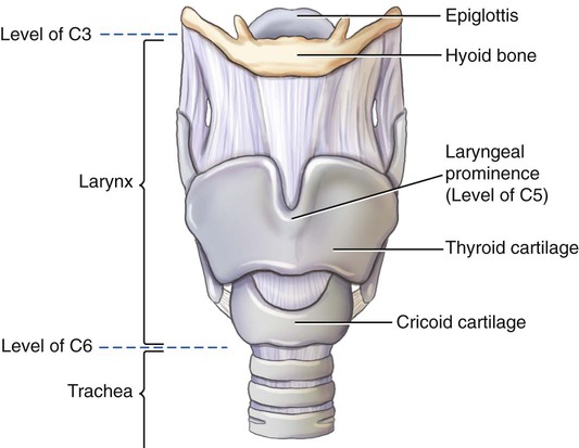
The larynx serves as the organ of voice. Sounds are made as air passes between the vocal cords located within the larynx (Fig. 2-6). The upper margin of the larynx is at the approximate level of C3. Its lower margin, where the larynx joins with the trachea, is at the level of C6.
The framework of the larynx consists of cartilages that are connected by ligaments and moved by numerous muscles that assist in the complex sound-making or voice process. The largest and least mobile of these cartilages is the thyroid cartilage, which consists of two fused platelike structures that form the anterior wall of the larynx. The prominent anterior projection of the thyroid cartilage is palpated easily and is known as the laryngeal prominence, or Adam's apple. This prominent structure is an important positioning landmark because it is easy to locate. The laryngeal prominence of the thyroid cartilage located at approximately the level of C5 is an excellent topographic reference for locating specific skeletal structures in this region.
The cricoid (kri′-koid) cartilage is a ring of cartilage that forms the inferior and posterior wall of the larynx. It is attached to the first ring of cartilage of the trachea.
One of the cartilages that make up the larynx is the uniquely shaped epiglottis, which resembles a leaf with the narrow distal stem portion attached to a part of the thyroid cartilage. As is described on the preceding page, the epiglottis flips down and covers the trachea during the act of swallowing (see arrow, Fig. 2-6).
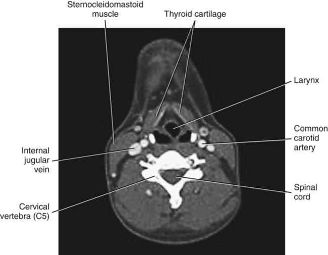
Axial sectional image of larynx
Because of the wide acceptance of CT (computed tomography) and MRI (magnetic resonance imaging), the technologist must recognize anatomic structures in cross-section. Fig. 2-7 shows an axial view of the midportion of the larynx at the level of C5. Only major structures are labeled in this section.
NOTE: Conventional CT images such as those seen here often are viewed as though one were facing the patient. Thus, the patient's right is to the viewer's left. This is the same way that conventional radiographs are placed for viewing (see Chapter 1).

Continuing from the larynx downward, the second division of the respiratory system proper is the trachea, or windpipe. It is a fibrous muscular tube about  inch (2 cm) in diameter and
  inches (11 cm) long. Approximately 20 C-shaped rings of cartilage are embedded in its walls. These rigid rings keep the airway open by preventing the trachea from collapsing during inspiration.
The trachea, located just anterior to the esophagus, extends from its junction with the larynx at the level of C6 (sixth cervical vertebra) downward to the level of T4 or T5 (fourth or fifth thoracic vertebra), where it divides into right and left primary bronchi.
Glands located near the respiratory system include the thyroid, parathyroid, and thymus glands.
The thyroid gland is a vascular organ that is located anteriorly in the neck region just below the larynx, with its right and left lateral lobes lying on each side and distal to the proximal trachea (Fig. 2-8). In an adult, it weighs 25 to 30 g (≈1 oz) and has a rich blood supply. As with other such glandular organs, the thyroid gland is more radiosensitive than many other body structures or organs. It is important for radiographers to know the relative size and location of this gland so that they can reduce exposure to these regions as much as possible by shielding and by collimation of the x-ray beam.
One unique feature of the thyroid gland is its ability to store certain hormones and release them slowly to aid in the regulation of body metabolism. These hormones also help to regulate body growth and development and activity of the nervous system, especially in children.
Parathyroid glands are small, round glands that are embedded in the posterior surface of the lateral lobes of the thyroid gland. Usually, two parathyroids are attached to each lateral thyroid lobe, as shown in Fig. 2-8. They store and secrete certain hormones that aid in specific blood functions, including maintenance of blood calcium levels.
Radiographs
AP and lateral radiographs of the upper airway allow visualization of the air-filled trachea and larynx. This AP radiograph (Fig. 2-9) shows a column of air primarily in the upper trachea region, as is seen in the lower half of the radiograph (darkened area, arrows). Certain enlargements or other abnormalities of the thymus or thyroid glands can be demonstrated on such radiographs, as can pathology within the airway system itself.
The lateral radiograph (Fig. 2-10) shows the air-filled trachea and larynx (A) and the region of the esophagus (B) and shows the locations relative to each other. The esophagus is located more posteriorly in relation to the trachea. The general locations of the thyroid gland (C) and the thymus gland (D) are also evident.
Axial Sectional Image of the Trachea
Fig. 2-11 is a CT image through the upper chest at the approximate level of T3. Observe that the trachea is located anteriorly to the esophagus and that both of these are anterior to the thoracic vertebrae. The upper lungs are located to each side of the trachea and the thoracic vertebrae.


Right and Left Bronchi
The third part of the respiratory system consists of the right and left primary bronchi, also known as the right and left main stem bronchi.
The right primary bronchus is wider and shorter than the left bronchus. The right primary bronchus is also more vertical; therefore, the angle of divergence from the distal trachea is less abrupt for the right bronchus than for the left. This difference in size and shape between the two primary bronchi is important because food particles or other foreign objects that happen to enter the respiratory system are more likely to enter and lodge in the right bronchus.
The right bronchus is about 2.5 cm long and 1.3 cm in diameter. The angle of divergence of the right bronchus is only about 25°.
The left bronchus is smaller in diameter (1.1 cm) than the right bronchus but about twice as long (5 cm). The divergent angle of the left primary bronchus is approximately 37°, which is more horizontal than the right bronchus. This increased angle and the smaller diameter make food particles or other foreign matter less likely to enter the left bronchus.
The carina (kah-ri′-nah) is a specific prominence, or ridge, of the lowest tracheal cartilage, which is seen at the bottom and inside portion of the trachea, where it divides into right and left bronchi. As viewed from above through a bronchoscope, the carina is to the left of the midline, and the right bronchus appears more open than the left, which clearly shows why particles that come down the trachea are more likely to enter the right bronchus.
The position of the carina, as shown in Fig. 2-12, is at the lower level of the division into the right and left primary bronchi. This is at the approximate level of T5 and is used as a specific reference point or level for CT of the thorax, as described in Chapter 18.
Secondary Bronchi, Lobes, and Alveoli
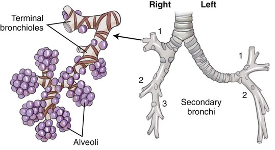
In addition to differences in size and shape between the right and left bronchi, another important difference is that the right bronchus divides into three secondary bronchi, but the left divides into only two, with each entering individual lobes of the lungs. The right lung contains three lobes, and the left lung contains two lobes, as is demonstrated in Figs. 2-13, 2-14, and 2-15. These secondary bronchi continue to subdivide into smaller branches, called bronchioles, that spread to all parts of each lobe.
Each of these small terminal bronchioles terminates in very small air sacs called alveoli. The two lungs contain 500 million to 700 million alveoli. Oxygen and carbon dioxide are exchanged in the blood through the thin walls of the alveoli.
Axial Sectional Image of Bronchi and Lungs
Fig. 2-14 represents an axial (sectional) image through the heart at the approximate level of T7.


The fourth and last division of the respiratory system comprises the two large, spongy lungs, which are located on each side of the thoracic cavity. The lungs fill all of the space not occupied by other structures. The right lung is made up of three lobes—the superior (upper), middle, and inferior (lower) lobes—divided by two deep fissures. The inferior fissure, which separates the inferior and middle lobes, is called the oblique fissure. The horizontal fissure separates the superior and middle lobes. The left lung has only two lobes—the superior (upper) and inferior (lower)—separated by a single deep oblique fissure.
The lungs are composed of a light, spongy, highly elastic substance called parenchyma (pah-reng′-ki-mah). This substance allows for the breathing mechanism responsible for expansion and contraction of the lungs, which brings oxygen into and removes carbon dioxide from the blood through the thin walls of the alveoli.
Each lung is contained in a delicate double-walled sac, or membrane, called the pleura, which can be visualized in both frontal (see Fig. 2-15) and sectional (Fig. 2-16) drawings. The outer layer of this pleural sac lines the inner surface of the chest wall and diaphragm and is called the parietal pleura. The inner layer that covers the surface of the lungs, also dipping into the fissures between the lobes, is called the pulmonary or visceral pleura (see Fig. 2-16).
The potential space between the double-walled pleura, called the pleural cavity, contains a lubricating fluid that allows movement of one or the other during breathing. When a lung collapses, or when air or fluid collects between these two layers, this space may be visualized radiographically. Air or gas present in this pleural cavity results in a condition called a pneumothorax, wherein air or gas pressure in the pleural cavity may cause the lung to collapse. Accumulation of fluid in the pleural cavity (pleural effusion) creates a condition called a hemothorax.
Axial Sectional Image of Lungs and Heart
Fig. 2-16 represents an axial sectional view through the lower third of the mediastinum and lungs. The double-walled membrane, the pleura, which completely encloses the lungs, including around the heart, is clearly shown. The outer membrane, the parietal pleura, and the inner membrane, the pulmonary (or visceral) pleura, are clearly visible, as is the potential space between them, the pleural cavity.
The double-walled pericardial sac, which surrounds the heart, is also identified. This drawing shows the relationship of the pericardial sac surrounding the heart with the pleural sac surrounding the lungs. The pleural and pericardial spaces or cavities are exaggerated on this drawing to show these parts better. Normally, no space exists between the double walls of the pericardial sac or between the parietal and visceral pleura unless pathology is present.
CT Axial Sectional Image
The CT image in Fig. 2-17 at the approximate level of T10 demonstrates the relationship and relative size of the heart, descending aorta, esophagus, and lungs. The heart is located more to the left, as can be seen on a PA chest radiograph. The heart is also shown to be located in the anterior portion of the chest cavity directly behind the sternum and left anterior ribs. The esophagus is posterior to the heart, with the descending aorta between the esophagus and the thoracic vertebrae. The right hemidiaphragm and upper liver are shown within the right lung region, indicating that this is a lower thoracic level image.


PA Chest Radiograph
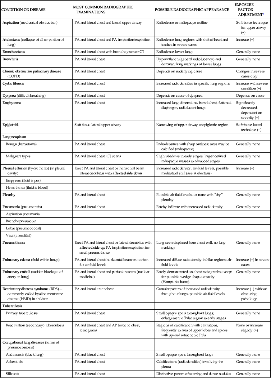
An enormous amount of medical information can be obtained from a properly exposed and carefully positioned PA chest radiograph. Although the technical factors are designed for optimal visualization of the lungs and other soft tissues, the bony thorax can also be seen. The clavicles, scapulae, and ribs can be identified through careful study of the chest radiograph in Fig. 2-18. The sternum and thoracic vertebrae are superimposed along with mediastinal structures, such as the heart and great vessels; therefore, the sternum and vertebrae are not well visualized on a PA chest radiograph.
The lungs and the trachea (see Fig. 2-18, dotted outline, A) of the respiratory system are well shown, although usually the bronchi are not seen easily. The first portion of the respiratory system, the larynx, is usually located above the top border of the radiograph and cannot be seen. The heart, large blood vessels, and diaphragm also are well visualized.
The labeled parts of the radiograph are also demonstrated in Fig. 2-19, a frontal view of the thorax with the bony structures removed. The thyroid gland, large blood vessels, and thymus gland are shown in relation to the lungs and heart.
Parts of Lungs
Radiographically important parts of the lungs (see Figs. 2-18 and 2-19) include the following.
The apex (B) of each lung is the rounded upper area above the level of the clavicles. The apices of the lungs extend up into the lower neck area to the level of T1 (first thoracic vertebra). This important part of the lungs must be included on chest radiographs.
The carina (C) is shown as the point of bifurcation, the lowest margin of the separation of the trachea into the right and left bronchi.
The base (D) of each lung is the lower concave area of each lung that rests on the diaphragm (E). The diaphragm is a muscular partition that separates the thoracic and abdominal cavities.
The costophrenic angle (F) refers to the extreme outermost lower corner of each lung, where the diaphragm meets the ribs. When positioning for chest radiographs, you should know the relative locations of the uppermost and lowermost parts of the lungs—the apices and the costophrenic angles, respectively—to ensure that these regions are included on every chest radiograph. Pathology, such as a small amount of fluid collection, would be evident at these costophrenic angles in the erect position.
The hilum (hilus) (G), also known as the root region, is the central area of each lung, where the bronchi, blood vessels, lymph vessels, and nerves enter and leave the lungs.
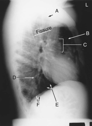
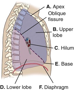
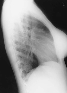
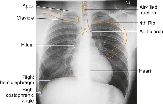
Lateral Chest View
The lateral chest radiograph (Fig. 2-20) is marked to show the same parts as those labeled in the accompanying drawing (Fig. 2-21). This drawing depicts the left lung as seen from the medial aspect. Because this is the left lung, only two lobes are seen. Some of the lower lobe (D) extends above the level of the hilum (C) posteriorly, whereas some of the upper lobe (B) extends below the hilum anteriorly. The posterior portion of the diaphragm is the most inferior part of the diaphragm. The single deep oblique fissure that divides the two lobes of the left lung is shown again, as is the end-on view of a bronchus in the hilar region.
The right lung is usually about 1 inch shorter than the left lung. The reason for this difference is the large space-occupying liver that is located in the right upper abdomen, which pushes up on the right hemidiaphragm. The right and left hemidiaphragms (F) are seen on the lateral chest radiograph in Fig. 2-20. The more superior of the two is the right hemidiaphragm, which is also seen on the PA chest radiograph (see Fig. 2-18).


Mediastinum
The medial portion of the thoracic cavity between the lungs is called the mediastinum. The thyroid and parathyroid glands, as described earlier in this chapter, are not considered mediastinal structures because they are located more superiorly and are not within the mediastinum. However, the thymus gland is located within the mediastinum, inferior to the thyroid gland and anterior to the trachea and esophagus (Fig. 2-22).
Four radiographically important structures located in the mediastinum are the (1) thymus gland, (2) heart and great vessels, (3) trachea, and (4) esophagus.
Thymus Gland
The thymus gland, located behind the upper sternum, is said to be a temporary organ because it is very prominent in infancy and reaches its maximum size of about 40 g at puberty, then gradually decreases in size until it almost disappears in adulthood. At its maximum size, it would appear much larger than the organ shown in Fig. 2-22. It may be visualized on chest radiographs of children but generally is not seen in adult radiographs because the denser lymphatic tissue has been replaced by less dense fat. At its maximum development, the thymus gland lies above and anterior to the heart and pericardium.
The thymus gland functions primarily during childhood and puberty to aid with the functioning of certain body immune systems that help the body resist disease. It is believed to contribute to the ability of the body to produce antibodies, which serve in rejecting foreign tissue and cells.
Heart and Great Vessels
The heart and the roots of the great vessels are enclosed in a double-walled sac called the pericardial sac (shown in Fig. 2-16). The heart is located posterior to the body of the sternum and anterior to T5 to T8. It lies obliquely in the mediastinal space, and approximately two-thirds of the heart lies to the left of the median plane.
The great vessels in the mediastinum are the inferior vena cava and superior vena cava, aorta, and large pulmonary arteries and veins. The superior vena cava is a large vein that returns blood to the heart from the upper half of the body (see Fig. 2-22). The inferior vena cava is a large vein that returns blood from the lower half of the body.
The aorta is the largest artery in the body (1 to 2 inches [2.5 to 5 cm] in diameter in an average adult). It carries blood to all parts of the body through its various branches. The aorta is divided into three parts: ascending aorta (coming up out of the heart); arch of the aorta; and descending aorta, which passes through the diaphragm into the abdomen, where it becomes the abdominal aorta.
Various pulmonary arteries and veins present in the mediastinum are shown in Figs. 2-23 and 2-24. These supply blood and return blood to and from all segments of the lungs. The capillary network surrounds the small air sacs, or alveoli, where oxygen and carbon dioxide are exchanged with the blood through the thin-walled air sacs.
See Chapter 17 for more complete drawings of the heart and great vessels as part of the total body circulatory system.
Trachea and Esophagus
The trachea, within the mediastinum, separates into the right and left primary and secondary bronchi, as shown in Fig. 2-23.
The proximal esophagus is located posterior to the trachea and continues down through the mediastinum anterior to the descending aorta until it passes through the diaphragm into the stomach.
Note in Fig. 2-24 that the heart is located in the anterior aspect of the thoracic cavity, directly behind the sternum.


Radiographic Positioning
Body Habitus
Body habitus requires special consideration in chest radiography. For example, a massively built hypersthenic patient has a thorax that is very broad and very deep from front to back but is shallow in vertical dimension, as is shown in the PA radiograph in Fig. 2-26. Therefore, care must be taken that the sides or the costophrenic angles are not cut off on a PA chest radiograph, which must be taken with the IR placed crosswise. Careful centering is also required on the lateral projection to ensure that the anterior or posterior margins are included on the radiograph.
The other extreme is a slender asthenic patient. With this build, the thorax is narrow in width and shallow from front to back but is very long in its vertical dimension. Therefore, in positioning for a chest radiograph, the technologist must ensure that the IR is long enough to include both the upper apex areas, which extend well above the clavicles, and the lower costophrenic angles. A chest PA radiograph in a nearer average hyposthenic patient is shown in Fig. 2-27. Care in vertical collimation for such patients must be exercised so that the costophrenic angles are not cut off on the lower margin.
Breathing Movements
Movements of the bony thorax during inspiration (taking air in) and expiration (expelling air) greatly change the dimensions of the thorax and the thoracic volume. To increase the volume of the chest during inspiration, the thoracic cavity increases in diameter in three dimensions.
The first of these is the vertical diameter, which is increased primarily by contraction and moving downward of the diaphragm, increasing the thoracic volume.
The transverse diameter is the second dimension that is increased during inspiration. The ribs swing outward and upward, and this increases the transverse diameter of the thorax.
The third dimension is the anteroposterior diameter, which is also increased during inspiration by the raising of the ribs, especially the second through sixth ribs.
During expiration, the elastic recoil of the lungs, along with the weight of the thoracic walls, causes the three diameters of the thorax to return to normal.
Degree of Inspiration
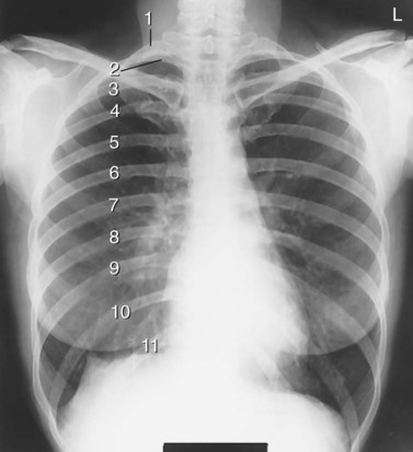
To determine the degree of inspiration in chest radiography, one should be able to identify and count the rib pairs on a chest radiograph. The first and second pairs are the most difficult to locate. When a chest radiograph is taken, the patient should take as deep a breath as possible and then hold it to aerate the lungs fully. Taking a second deep breath before holding it allows for a deeper inspiration.
The best method that can be used to determine the degree of inspiration is to observe how far down the diaphragm has moved by counting the pairs of posterior ribs in the lung area above the diaphragm. A general rule for average adult patients is to “show” a minimum of 10 on a good PA chest radiograph. To determine this, start at the top with the first rib and count down to the tenth or eleventh rib posteriorly. The posterior part of each rib, where it joins a thoracic vertebra, is the most superior part of the rib. The diaphragm should always be checked to see that it is below the level of at least the tenth posterior rib (see following Note). (Fig. 2-30 shows 11 posterior ribs, which can be expected in many healthy patients.)
NOTE: Patients with pulmonary diseases and trauma may be unable to inspire deeply. Therefore, it may be impossible to demonstrate 10 ribs above the diaphragm for these chest projections.


Positioning Considerations
Patient preparation for chest radiography includes the removal of all opaque objects from the chest and neck regions, including clothes with buttons, snaps, hooks, or any objects that would be visualized on the radiograph as a shadow (radiopaque artifact). To ensure that all opaque objects are removed from the chest region, the usual procedure is to ask the patient to remove all clothing, including bras, necklaces, or other objects around the neck. The patient then puts on a hospital gown, which commonly has the opening in the back.
Long hair braided or tied together in bunches with rubber bands or other fasteners may cause suspicious shadows on the radiograph if left superimposing the chest area. Oxygen lines or electrocardiogram (ECG) monitor leads should be moved carefully to the side of the chest if possible. All radiopaque objects should be moved carefully from the radiographic field of interest to prevent artifacts from interfering with the quality of the diagnostic image.
Radiation Protection
Patients should be protected from unnecessary radiation for all diagnostic radiographic examinations, especially for chest radiographs because these are the most common of all radiographic examinations.
Although the chest radiographic examination often is considered the simplest of all radiographic procedures, it also is the examination with the highest number of repeats in many radiology departments. Therefore, unnecessary radiation exposure from repeat exposures should be minimized by taking extra care in positioning, CR centering, and selecting correct exposure factors if automatic exposure control (AEC) systems are not used. Reduce patient dose as much as possible through the use of correct radiation protection practices by close collimation and protective shielding.
In addition to careful collimation, a lead shield should be used to protect the abdominal area below the lungs. This shielding is especially important for children, pregnant women, and all individuals of childbearing age. A minimal rule is that shielding should be used on all patients of reproductive age. However, many departments have a general policy of shielding for all patients undergoing chest radiography.
A common type of shield for chest radiography is a type of freestanding, adjustable mobile shield placed between the patient and the x-ray tube. A vinyl-covered lead shield that ties around the waist can also be used. Both of these types of shields should provide shielding from the level of the iliac crests, or slightly higher, to the midthigh area.
To protect the gonads from scatter and secondary radiation from the cassette or IR holder device and the wall behind it, some references suggest that a freestanding shield or a wraparound shield also should be placed over the radiosensitive structures outside the anatomy of interest between the patient and the IR.
Technical Factors
Kilovoltage (kV) should be high enough to result in sufficient contrast to demonstrate the many shades of gray needed to visualize finer lung markings. In general, chest radiography uses low contrast, described as long-scale contrast, with more shades of gray. This requires a high kV of 110 to 125. This kV range typically is used for both analog and digital imaging systems.
Lower kV, yielding high contrast, would not provide sufficient penetration to allow clear visualization of the fine lung markings in the areas behind the heart and lung bases. Too high contrast is evident when the heart and other mediastinal structures appear underexposed, even though the lung fields are sufficiently penetrated.
As a general rule, in chest radiography, the use of high kV (>100) requires the use of grids. Moving grids or fine-line focused fixed grids can be used. Exceptions are mobile chest projections taken with equipment that is limited to 80 to 90 kV, for which IRs without grids may be used, but this is not recommended.
Exposure Time and Milliamperage (mAs–Milliampere Seconds)
Generally, chest radiography requires the use of high (mAs) mA and short exposure time to minimize the chance of motion and resultant loss of sharpness.
Sufficient mAs should be used to provide for optimum density (brightness) of lungs and mediastinal structures. A determining factor for this on PA chest radiographs is to be able to see faint outlines of at least the mid and upper vertebrae and posterior ribs through the heart and other mediastinal structures.
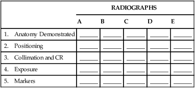
Throughout the positioning sections of this text, the correct or best placement of patient identification (ID) information and image markers is indicated. The top portion of each positioning page includes a drawing that demonstrates the correct IR size and placement (lengthwise or crosswise) and indicates the best location for the patient ID blocker (analog systems) and the location and type of image marker used for that specific projection or position.
Pediatric Applications
Generally, with newborns and small infants, for whom head support is required, chest radiographs are taken AP supine. Laterals also may be taken supine with a horizontal beam to demonstrate fluid levels (dorsal decubitus). However, erect PA and laterals are preferred whenever possible, with the use of immobilization devices such as the Pigg-O-Stat (Modern Way Immobilizers, Inc, Clifton, Tennessee) (described in Chapter 16).
Lower kV (70 to 85) and less mAs are required for pediatric patients with the shortest exposure time possible (to prevent motion). Higher speed imaging systems or receptors generally are used with pediatric patients for two reasons: (1) to reduce the chance of motion and (2) to reduce the patient exposure dose (important because of the sensitivity of young tissue to radiation exposure). See Chapter 16 for more detailed information on special positioning considerations required with pediatric patients.
Geriatric Applications
Frequently, older patients have less inhalation capability with resultant “more shallow” lung fields, and a higher CR location is required (CR to T6-7, p. 83).
Instructions and Patient Handling
More care, time, and patience frequently are required when breathing and positioning requirements are explained to geriatric patients. Help and support provided to these patients during the positioning process are important. Arm supports for keeping the arms raised high for the lateral position are essential for many older patients.
Breathing Instructions
Breathing instructions are very important in chest radiography because any chest or lung movement that occurs during the exposure results in “blurring” of the radiographic image. Chest radiographs must be taken on full inspiration to show the lungs as they appear fully expanded.
Hold Breath on Second Inspiration
More air can be inhaled without too much strain on the second breath compared with the first. Therefore, the patient should be asked to hold the second full inspiration rather than the first. However, the full inspiration should not be forced to the point of strain that causes unsteadiness; this should be explained to the patient before the exposure as the patient is being positioned.
Inspiration and Expiration
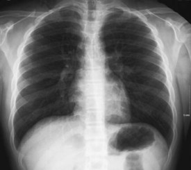
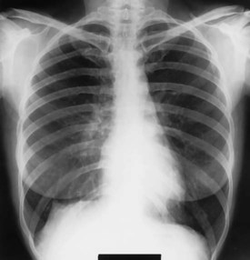
Occasional exceptions have been noted to taking chest radiographs on full inspiration only. For certain conditions, comparison radiographs are taken on both full inspiration and full expiration. Indicators for this include a possible small pneumothorax (air or gas in the pleural cavity), fixation or lack of normal movement of the diaphragm, the presence of a foreign body, and the need to distinguish between an opacity in the rib and one in the lung. When such comparison radiographs are taken, they should be labeled “inspiration” and “expiration.”
Note the number of ribs demonstrated above the diaphragm on the expiration projection (Fig. 2-32). There are a greater number of ribs demonstrated above the diaphragm in Fig. 2-31. Also note the position of the two opacities in the right lung between inspiration and expiration projections. They shift position, which indicates they are within the lungs or pleura. Note also the number of ribs visible above the diaphragm, indicating the degree of inspiration (10 posterior ribs) and expiration (8 posterior ribs).
Erect Chest Radiographs
All chest radiographs should be taken in an erect position if the patient's condition allows. Three reasons for this are as follows:
1. The diaphragm is allowed to move down farther. An erect position causes the liver and other abdominal organs to drop, allowing the diaphragm to move farther down (inferior) on full inspiration and allowing the lungs to aerate fully.
2. Air and fluid levels in the chest may be visualized. If both air and fluid are present within a lung or within the pleural space, the heavier fluid, such as blood or pleural fluid resulting from infection or trauma, gravitates to the lowest position, whereas the air rises. In the recumbent position, a pleural effusion spreads out over the posterior surface of the lung, producing a hazy appearance of the entire lung. In the upright position, free fluid is located near the base of the lung. The PA erect chest radiograph (Fig. 2-33) shows some fluid in the left lower thoracic cavity near the base of the lung. The supine radiograph taken on a different patient (Fig. 2-34) demonstrates a generalized hazy appearance of the entire right lung, resulting from the presence of fluid now spread throughout the right thorax.
3. Engorgement and hyperemia of pulmonary vessels may be prevented. The term engorgement literally means “distended or swollen with fluid.” Hyperemia (hy″-per-e′-me-ah) is an excess of blood that results in part from relaxation of the distal small blood vessels or arterioles.*
An erect position tends to minimize engorgement and hyperemia of pulmonary vessels, whereas a supine position increases these, which can change the radiographic appearance of these vessels and the lungs in general.
PA 72-Inch (183-cm) source image receptor distance
Chest radiographs taken AP rather than PA at 72 inches (183 cm) result in increased magnification of the heart shadow, which complicates the diagnosis of possible cardiac enlargement. The reason for this increased magnification is the anterior location of the heart within the mediastinum; placing it closer to the IR on the PA results in less magnification. A longer source to image receptor distance (SID), such as 72 inches [183 cm], magnifies less because the x-ray beam has less divergence.


Evaluation Criteria
The description for each chest projection or position in this chapter includes an evaluation criteria section. This section lists and describes specific criteria by which one can evaluate the resultant radiograph. The goal of every technologist should be to take the “optimal” radiograph. These criteria provide a definable standard by which every chest radiographic image can be evaluated to determine where improvements can be made.
Important evaluation criteria for all routine PA and lateral chest radiographs are described in the following sections.
PA Chest Positioning
True PA, No Rotation
Even a slight amount of rotation on a PA chest projection results in distortion of size and shape of the heart shadow because the heart is located anteriorly in the thorax. Therefore, it is important that there be no rotation. To prevent rotation, ensure that the patient is standing evenly on both feet with both shoulders rolled forward and downward. Also, check the posterior aspect of the shoulders and the lower posterior rib cage and the pelvis to ensure no rotation. Scoliosis and excessive kyphosis make it more difficult to prevent rotation. Scoliosis is lateral, or side-to-side, curvature of the spine, which frequently is combined with excessive kyphosis, a humpback curvature. Together, these spinal curvatures frequently result in “twisting” deformity of the bony thorax, making a true PA without some rotation more difficult or impossible.
Rotation on PA chest radiographs can be determined by examination of both sternal ends of the clavicles for a symmetric appearance in relationship to the spine. On a true PA chest without rotation, both the right and the left sternal ends of the clavicles are the same distance from the center line of the spine. Note the rotation evident in Fig. 2-36 by the difference in distance between the center of the spinal column and the sternal end of the right clavicle compared with the left.
The direction of rotation can be determined by noting which sternal end of the clavicle is closest to the spine. For example, in Fig. 2-36, the left side of the thorax is moved toward the IR (right side moved away from IR), which creates a slight left anterior oblique (LAO) that decreases the distance of the left clavicle from the spine.
Extending the Chin
Sufficient extension of the patient's neck ensures that the chin and neck are not superimposing the uppermost lung regions, the apices of the lungs. This is demonstrated by the two radiographs in Figs. 2-37 and 2-38. Also, ensure that the upper collimation border is high enough so that the apices are not cut off.
Minimizing Breast Shadows
A patient with large pendulous breasts should be asked to lift them up and outward and then to remove her hands as she leans against the chest board (IR) to keep them in this position. This position lessens the effect of breast shadows over the lower lung fields. However, depending on the size and density of the breasts, breast shadows over the lower lateral lung fields cannot be totally eliminated (Fig. 2-39).


Lateral Chest Positioning
Side Closest to IR
The patient's side closest to the IR is best demonstrated on the finished radiograph. A left lateral should be performed unless departmental protocol indicates otherwise, or unless certain pathology in the right lung indicates the need for a right lateral. A left lateral more accurately demonstrates the heart region (without as much magnification) because the heart is located primarily in the left thoracic cavity.
True Lateral, No Rotation or Tilt
Ensure that the patient is standing straight with weight evenly distributed on both feet and arms raised. As a check against rotation, confirm that the posterior surfaces of the shoulder and the pelvis are directly superimposed and perpendicular to the IR. Because of the divergent x-ray beam, the posterior ribs on the side farthest away from the IR are magnified slightly and projected slightly posterior compared with the side closest to the IR on a true lateral chest; this is more noticeable on a broad-shouldered patient. However, this separation of posterior ribs resulting from divergence of the x-ray beam at the commonly used 72-inch (183-cm) SID should be only  to
to  inch, or about 1 cm. Any greater separation than this indicates rotation of the thorax from a true lateral position.*
NOTE: Some references recommend an intentional slight anterior rotation of the side away from the IR so that the posterior ribs are directly superimposed. This rotation may be preferred in some departments, but because the heart and most lung structures are near-midline structures and are not affected by the beam divergence, a straight lateral with respect to the IR is more common; this causes slight separation of the posterior ribs and costophrenic angles, as described earlier.
Fig. 2-41 shows a lateral chest with excessive rotation, as indicated by the amount of separation of the right and left posterior ribs and separation of the two costophrenic angles. This represents a positioning error and generally would require a repeat radiograph.
Direction of Rotation
The direction of rotation on a lateral chest is sometimes difficult to determine. Frequently, however, this can be done by identifying the left hemidiaphragm by the gastric air bubble in the stomach or by the inferior border of the heart shadow, both of which are associated with the left hemidiaphragm.*
No Tilt
There also should be no tilt, or leaning “sideways.” The midsagittal plane must be parallel to the IR. If the patient's shoulders are placed firmly against the chest board (IR) on a lateral chest, the lower lateral thorax or hips or both may be 1 or 2 inches away. This is especially true on broad-shouldered patients. Tilt, if present, may be evident by closed disk spaces in the thoracic vertebra.
Arms Raised High
Ensure that the patient raises both arms sufficiently high to prevent superimposition on the upper chest field. Patients who are weak or unstable may need to grasp a support (Fig. 2-42).
When the patient's arms are not raised sufficiently, the soft tissues of the upper arm superimpose portions of the lung field, as is demonstrated in Fig. 2-43. Arrows show margins of soft tissues of the arms overlying upper lung fields. This would require a repeat and should be avoided.


CR Location
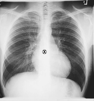
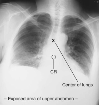
The top of the shoulder traditionally has been used for chest positioning. This method includes placing the top of the cassette or other IR  to 2 inches (4 to 5 cm) above the shoulders and centering the CR to the center of the IR. However, this positioning method is inconsistent, given variations in lung field dimensions owing to differences in body habitus, as demonstrated by a comparison of Figs. 2-44 and 2-45. The small circle indicates where the CR was placed on these two patients. The center of the lungs (indicated by X) is shown to be near the center of the IR for the male patient in Fig. 2-44 but is above center on the small and older female patient in Fig. 2-45. This centering error unnecessarily exposes a large portion of the upper abdomen.
These variations demonstrate the importance of a chest positioning method that consistently centers the CR to the center of the lung fields on all types of patients with accurate collimation on both top and bottom.
CR Chest-Positioning Method
Bony landmarks are consistent and reliable as a means of determining CR locations. Landmarks for locating the center of the lung fields are as follows.
Vertebra Prominens (PA Chest)
The vertebra prominens corresponds to the level of T1 and the uppermost margin of the apex of the lungs. This landmark, which can be palpated at the base of the neck, is the preferred landmark for locating the CR on a PA chest (Figs. 2-46 and 2-47). For an average woman, this is down about 7 inches (18 cm); for a man, this is down about 8 inches (20 cm).
One method of determining this distance is by using an average hand spread as shown. Most hands can reach 7 inches (18 cm). The 8-inch (20-cm) distance can be determined by estimating an additional inch. If the hand spread method is used, practice with a ruler to determine these distances consistently.
These differences between male and female are true for near-average body types in the general population, with crossover exceptions in which certain larger athletic women may have longer lung fields and some men may have shorter lungs. However, for purposes of chest positioning for the general population, the average measurements of 7 inches (18 cm) for a woman and 8 inches (20 cm) for a man can be used as reliable guidelines.
Other noteworthy exceptions in centering involve variations in body type. For example, the author found that 15% to 20% of the general male population consisted of the well-developed athletic sthenic/hyposthenic type, which requires centering nearer to T8, or 9 inches (23 cm) down from the vertebra prominens. The hypersthenic type describes about 5% to 10% of the population, which requires centering only from 6 to 7 inches (15 to 18 cm) down.
NOTE: For most patients, this CR level for PA chests is near the level of the inferior angle of the scapula, which corresponds to the level of T7 on an average patient.


The easily palpated jugular notch is the recommended landmark for location of the CR for AP chest radiographs. The level of T7 on an average adult is 3 to 4 inches (8 to 10 cm) below the jugular notch. For most older or hypersthenic patients, this is approximately 3 inches (8 cm). For younger or sthenic/hyposthenic athletic types, this is nearer 4 to 5 inches (10 to 13 cm).
This distance also can be determined by the technologist's hand width. The average-sized hand width with the fingers together is approximately 3 inches (8 cm). (See Fig. 2-50.)
Lung Dimensions and IR Placement
PA or AP chest radiographs frequently have been described with the cassette or IR placed lengthwise as the preferred placement for an average patient. However, contrary to common belief, the width or horizontal dimension of the average PA or AP chest is greater than the vertical dimension. The technologist should use his or her discretion to determine whether the IR should be placed lengthwise (portrait) or crosswise (landscape) for PA or AP projections based on the size and body habitus of the patient, ensuring that the right and left costophrenic angles of the lungs are not cut off.
A survey conducted by the author also shows that the width or horizontal dimension on a PA or AP chest exceeds 13 inches (33 cm) on 15% to 20% of patients. This requires that the 14 × 17-inch (35 × 43-cm) IR be placed crosswise so as not to cut off lateral lung margins on these patients.
Some erect PA chests are performed with digital chest systems, which have a 43- × 43-cm (17- × 17-inch) image receptor that will accommodate both long and broad chest dimensions.
As the patient is standing and facing the chest IR, one can determine whether to place the IR crosswise on larger patients by standing behind the patient and placing one's hands squarely on each side of the chest. If there is any doubt that both sides of the chest can be included, the IR should be placed crosswise because the height of the average lung field is less than the width.
NOTE: Newer digital chest units may include larger IRs (e.g., 43 × 49 cm [17 × 19 inches]), which eliminates this concern.
For recumbent AP chest radiographs (usually taken at <72 inches [183 cm], with an accompanying increase in divergence of the x-ray beam), the chance that the side borders of the lungs may be cut off is increased when the IR is placed lengthwise. It is recommended that for most AP chest radiographs, the 14 × 17-inch (35 × 43-cm) IR should be placed crosswise. The IR and CR should be centered to a point 3 to 4 inches (8 to 10 cm) below the jugular notch (Fig. 2-50).
Collimation Guidelines
Side collimation borders can be determined easily by adjusting the illuminated field margins to the outer skin margins on each side of the posterior chest surface (given that lungs expand during deep inspiration). However, the upper and lower collimation borders are more difficult to determine because these lung margins are not visible externally.
A reliable method for upper and lower chest collimation is to adjust the upper border of the illuminated light field to the vertebra prominens, which (with the divergent rays) results in an upper collimation margin on the IR of about  inches, or 4 cm, above the vertebra prominens (Fig. 2-51). This also results in a lower collimation border of 1 to 2 inches (2.5 to 5 cm) below the costophrenic angles, if the CR was centered correctly. These distances above and below the lungs allow for some margin of error in CR placement without cutting off upper or lower lungs.


Digital Imaging Considerations
Guidelines as listed next should be followed when chest images are acquired through the use of digital imaging technology. (See Chapter 1 for a discussion of applications of digital technology.)
1. Collimation. In addition to the benefit of reducing radiation dose to the patient, collimation that is closely restricted to the part that is being examined is key in ensuring that the image processed by the computer is of optimal quality. Close collimation also improves image quality by preventing secondary and scatter radiation from surrounding areas (e.g., the dense abdomen below) from reaching the highly sensitive photostimulable storage phosphor plate (PSP ) or direct digital IRs. With the digital IR being larger than other IRs, close collimation is critical for patient dose reduction and improved image quality. Close collimation also allows the computer to provide accurate information regarding the exposure indicator.
2. Accurate centering. Because of the technique used by the CR or DR IR, it is important that the body part and CR be accurately centered to the IR. In chest imaging, this involves centering the CR to the center of the lung fields, as described previously.
3. Exposure factors. Digital imaging systems are known for their wide exposure latitude; they are able to process an acceptable image from a broad range of exposure factors (kV and mAs). However, the ALARA (as low as reasonably achievable) principle related to patient exposure still must be followed, and the lowest exposure factors required to obtain a diagnostic image must be used. This includes using the highest possible kV and the lowest mAs consistent with optimal image quality.
4. Post-processing evaluation of exposure indicator. When the image is available for viewing, it is critiqued for positioning and exposure accuracy. The technologist must also check the exposure indicator to verify that the exposure factors used were in the correct range to ensure optimal quality with the least radiation to the patient.
Alternative Modalities or Procedures
Conventional Tomography and CT
CT is performed frequently to examine and identify pathology in the mediastinum or in the lungs. Helical CT provides much faster scanning, which is especially advantageous in the thoracic region. When nonhelical CT is used for imaging small thoracic masses, problems occur with nonuniform breath holds (patient not holding breath in the same position for each exposure). Helical scanners with multiple detectors can produce high-resolution images of the heart and lung. (See Chapter 18.)
Sonography
Sonography (ultrasound) may be used to detect pleural effusion (fluid within pleural space) or for guidance when a needle is inserted to aspirate the fluid (thoracentesis).
An echocardiogram is an ultrasound examination in which sound waves are used to create an image of the heart. (This is not the same as an ECG, which is a completely different type of examination that assesses the electrical activity of the heart.)
Nuclear Medicine
Certain nuclear medicine procedures involving radionuclides can be used to evaluate and diagnose pulmonary diffusion conditions or pulmonary emboli. With the use of SPECT (single-photon emission computed tomography), the heart can be evaluated specifically for myocardial infarction.
MRI
Cardiovascular MRI procedures can be performed to demonstrate and evaluate pathology including congenital heart disorders, graft patency, cardiac tumors, thrombi, pericardial masses, and aortic dissection and aneurysm. MRI is unlikely to replace echocardiography for cardiac evaluation. However, MRI can be used as an adjunct to CT to provide multiplanar views of tumors and masses, to assess mediastinal pathology further, and to evaluate aortic dissection and aneurysm.
Clinical Indications
The clinical indications, as listed subsequently and in each chapter of this textbook, are not intended to be inclusive of all diseases or pathologic conditions of which technologists should be aware or that may be covered in a separate pathology course. However, they do represent conditions that are encountered more commonly, and knowledge and understanding of these clinical indications should be considered routine and essential for all technologists.
Patient histories in which these clinical indications are noted help the technologist select the optimum exposure factors and ensure that the necessary projections or body positions are being used. When adjusting the exposure factors, the technologist must ensure that a quality diagnostic image is obtained without obscuring or accentuating the disease process.
This information is also important for the technologist in understanding and being prepared to respond to patient needs and reactions during the radiographic procedure. For the chest, these clinical indications are numerous and complex. The more common indications for youth and adults are listed alphabetically as follows (see Chapter 16 for information on infants and children).
Indications
Aspiration (as-pi-ra′-shun) (mechanical obstruction) is most common in small children when foreign objects are swallowed or aspirated into the air passages of the bronchial tree. In adults, it may occur with food particles, creating coughing and gagging (relieved by the Heimlich maneuver). Aspiration may be evident in the lower airways on frontal and lateral chest radiographs or AP and lateral radiographs of the upper airway.
Atelectasis (at″-e-lek′-tah-sis) is a condition rather than a disease, in which collapse of all or a portion of a lung occurs as the result of obstruction of the bronchus or puncture or “blowout” of an air passageway. With less air in the lung than normal, this region appears more radiodense, and this may cause the trachea and heart to shift to the affected side.
Bronchiectasis (brong″-ke-ek′-tah-sis) is an irreversible dilation or widening of bronchi or bronchioles that may result from repeated pulmonary infection or obstruction. Areas of bronchial walls are destroyed and become chronically inflamed, resulting in increased production of mucus and causing chronic cough and expectoration (coughing up sputum). Pus can collect in dilated regions, resulting in an increase in regional radiodensity with less air in these regions (most common in the lower lobes).
Bronchitis (brong-ki′-tis) is an acute (short-term) or chronic (long-term) condition in which excessive mucus is secreted into the bronchi, causing cough and shortness of breath. The chief cause is cigarette smoking. Infectious bronchitis is caused by viruses or bacteria. Bronchitis generally involves lower lobes and in severe cases is demonstrated on radiographs by hyperinflation and more dominant lung markings.
Chronic obstructive pulmonary disease (COPD) is a form of persistent obstruction of the airways that usually causes difficulty in emptying the lungs of air; it may be caused by emphysema or chronic bronchitis (smoking is the predominant cause of COPD). Asthma also is considered a COPD. Mild cases of COPD usually are not detectable on chest radiographs, but more severe conditions are clearly demonstrated. (See emphysema further on.)
Cystic fibrosis (sis′-tik fi-bro′-sis), the most common of inherited diseases, is a condition in which secretions of heavy mucus cause progressive “clogging” of bronchi and bronchioles. This may be evident on chest radiographs as increased radiodensities in specific lung regions, along with hyperinflation.
Dyspnea (disp′-ne-ah) is a condition of shortness of breath, which creates a sensation of difficulty in breathing; it is most common in older persons. Although generally caused by physical exertion, it may be caused by restrictive or obstructive defects within the lungs or airways. Dyspnea also may be caused by pulmonary edema related to cardiac conditions. PA and lateral chest radiographs are commonly taken as an initial procedure followed by other examinations in an effort to make a diagnosis.
Emphysema (em″-fi-se′-mah) is an irreversible and chronic lung disease in which air spaces in the alveoli become greatly enlarged as a result of alveolar wall destruction and loss of alveolar elasticity. Air tends not to be expelled during expiration, resulting in seriously labored breathing with impedance of gas exchange within the lungs. Causes include smoking and long-term dust inhalation. In severe cases, emphysema is evident on chest radiographs by increased lung dimensions, barrel chest with depressed and flattened diaphragm obscuring costophrenic angles, and an elongated heart shadow. Lung fields appear very radiolucent, requiring a significant decrease in exposure factors from a normal chest, even with the increased chest dimensions.
Epiglottitis (ep″-i-glo-ti′-tis) is most common in children ages 2 to 5. See Chapter 16 for more information on this serious, life-threatening condition, which can develop very rapidly. A soft tissue lateral of the upper airway may demonstrate edema or swelling at the point of the epiglottis.
Neoplasm refers to a new growth or tumor. Neoplasms may be benign (noncancerous) or malignant (cancerous).
Many types of lung cancers have been identified, and more than 90% start in the bronchi (bronchogenic carcinoma). Less common is alveolar cell carcinoma, which originates in the alveoli of the lungs. Also, many cancers, such as breast, colon, and prostate, start elsewhere in the body before spreading to the lungs as pulmonary metastases. Studies have shown that smoking is the primary cause in about 90% of all lung cancers in men and 70% in women.
Lung cancer may be demonstrated on chest radiography as slight shadows in the early stages and as more sharply defined, larger radiopaque masses in more advanced cases. Malignant lung tumors rarely calcify; therefore, calcified radiopaque masses or nodules are generally benign.
CT scans may reveal small nodules that are not yet seen on chest radiographs. Biopsies usually are required to determine whether these shadows are the result of inflammation or are cancerous.
Pleural effusion (an older, outdated term is hydrothorax) is a condition of abnormal accumulation of fluid in the pleural cavity. Types of pleural effusion include the following.
Empyema (em″-pi-e′-mah) occurs when the fluid is pus. Empyema may be caused by chest wounds, obstruction of bronchi, or ruptured lung abscess. It may develop when pneumonia or a lung abscess spreads into the pleural space.
Hemothorax (he″-mo-thor′-aks) occurs when the fluid is blood. A common cause of right-sided or bilateral pleural effusion is congestive heart failure. Causes of left-sided effusion include trauma, pulmonary infarct, pancreatitis, and subphrenic abscess.
Any type of pleural effusion is demonstrated by fluid levels on horizontal beam chest radiographs. Small amounts are best shown by a lateral decubitus position with affected side down or with erect positioning.
Pleurisy (ploor′-i-se) is characterized by inflammation (usually caused by a virus or bacterium) of the pleura surrounding the lungs. The cause is visceral and parietal pleura “rubbing” during respiration, which results in severe pain. It frequently follows pneumonia or trauma to the chest. Pleurisy may be demonstrated radiographically by associated pleural effusion. A condition called “dry pleurisy” does not include fluid accumulation and generally is not visible on radiographs.
Pneumonia (noo-mon′-ya) (pneumonitis) is an inflammation of the lungs that results in accumulation of fluid within certain sections of the lungs, creating increased radiodensities in these regions. The most common initial diagnostic examination consists of PA and lateral erect horizontal beam radiographs. Types of pneumonia are derived from the location and cause of the inflammation. Normal exposure factors generally are used initially. The radiologist may request secondary images with increased density (brightness) to see through the area of interest to rule out a lesion in the same anatomic region when film-screen imaging methods are being employed. The different types of pneumonia include the following.
Aspiration pneumonia is caused by aspiration of a foreign object or food into the lungs, which irritates the bronchi, resulting in edema.
Bronchopneumonia is bronchitis of both lungs that most commonly is caused by Streptococcus or Staphylococcus bacteria.
Lobar pneumonia generally is confined to one or two lobes of the lungs.
Viral (interstitial) pneumonia causes inflammation of the alveoli and connecting lung structures. It most commonly is evident as increased radiodensities in the region surrounding the hila.
Pneumothorax (noo″-mo-thor′-aks) is an accumulation of air in the pleural space that causes partial or complete collapse of the lung and results in immediate and severe shortness of breath and chest pain. It may be caused by trauma or a pathologic condition that causes spontaneous rupture of a weakened area of lung.
Radiographically, the affected lung can be seen displaced away from the chest wall. Most evident on chest radiographs is the fact that no lung markings are seen in the region of the collapsed lung. Care should be taken to identify the lung edge or boundary. Chest radiographs for pneumothorax should be taken erect. If the patient cannot assume an erect position, a horizontal beam lateral decubitus position with the affected side up should be taken (not down as with pleural effusion).
Erect PA inspiration/expiration radiographs often are taken to demonstrate a small pneumothorax, which is best seen at the apex of an erect PA radiograph with maximum expiration.
Pulmonary edema is a condition of excess fluid within the lung that most frequently is caused by a backup in pulmonary circulation commonly associated with congestive heart failure. A common cause is coronary artery disease, in which blood flow to the heart muscle is restricted. Coronary artery disease weakens the heart and results in inadequate pulmonary circulation, causing backup of blood in the lungs. The condition is seen on chest radiographs as a diffuse increase in radiodensity in the hilar regions fading toward the periphery of the lung and as increased air-fluid levels with horizontal beam projections in more severe conditions.
Respiratory distress syndrome (RDS) (commonly called hyaline membrane disease [HMD] in infants and adult respiratory distress syndrome [ARDS] in adults) is an emergent condition in which the alveoli and capillaries of the lung are injured or infected, resulting in leakage of fluid and blood into the spaces between alveoli or into the alveoli themselves with formation of hyaline membranes. (HMD results from a lack of lung development in which the alveoli collapse as the result of lack of internal tension.) This leakage can be detected radiographically as increased density (brightness) throughout the lungs in a granular pattern as the normally air-filled spaces are filled with fluid. The most common radiographic sign is an “air bronchogram.”
Tuberculosis (too-ber″-ku-lo′-sis) (TB) is a contagious disease (potentially fatal) that is caused by airborne bacteria. At one time, TB resulted in more than 30% of all deaths, but the development of vaccines and antibiotics such as streptomycin in the 1940s and 1950s nearly eliminated the threat of this disease. However, occurrence of TB has begun to increase again with the increased incidence of acquired immunodeficiency syndrome (AIDS) and in the presence of urban overcrowding and unsanitary conditions.
Primary tuberculosis refers to TB that occurs in persons who have never had the disease before. Hilar enlargement, along with enlarged mediastinal lymph nodes, is an important indicator of primary TB. Small focal spot lesions may be found anywhere in the lungs, and unilateral pleural effusion is common, especially in adults.
Reactivation (secondary) tuberculosis usually develops in adults and generally is first evident on radiography bilaterally in the upper lobes as irregular calcifications that are mottled in appearance. Upward retraction of the hila is frequently evident. As healing occurs, fibrous tissue develops with calcification surrounding the region and leaving a type of cavity that can be seen on tomograms of this region. AP lordotic projections are frequently requested for visualization of calcifications and cavitations of the apices and upper lobes.
Occupational lung disease (forms of pneumoconiosis)
Anthracosis (an″-thre-ko′-sis), also called black lung pneumoconiosis, is caused by deposits of coal dust. With long-term inhalation (≥10 years), it spreads throughout the lungs and is seen on chest radiographs as small opaque spots or conglomerate masses.
Asbestosis (as″-bes-to′-sis) is caused by inhalation of asbestos dust (fibers) that results in pulmonary fibrosis. It may develop into lung cancer, especially in smokers.
Silicosis (sil″-i-ko′-sis) is a permanent condition of the lungs that is caused by inhalation of silica (quartz) dust, a form of sand dust. Occupational exposures include certain types of mine work, sandblasting, and similar professions. Chest x-rays show distinctive patterns of nodules and scarring densities. Patients with silicosis are three times more likely to develop TB than are persons without silicosis.*
SUMMARY OF CLINICAL INDICATIONS
| CONDITION OR DISEASE | MOST COMMON RADIOGRAPHIC EXAMINATIONS | POSSIBLE RADIOGRAPHIC APPEARANCE | EXPOSURE FACTOR ADJUSTMENT* |
| Aspiration (mechanical obstruction) | PA and lateral chest and lateral upper airway | Radiodense or radiopaque outline | Soft tissue technique for upper airway (−) |
| Atelectasis (collapse of all or portion of lung) | PA and lateral chest and PA inspiration/expiration | Radiodense lung regions with shift of heart and trachea in severe cases | Increase (+) |
| Bronchiectasis | PA and lateral chest with bronchogram or CT | Radiodense lower lungs | Generally none |
| Bronchitis | PA and lateral chest | Hyperinflation (general radiolucency) and dominant lung markings of lower lungs | Generally none |
| Chronic obstructive pulmonary disease (COPD) | PA and lateral chest | Depends on underlying cause | Changes in severe cases only |
| Cystic fibrosis | PA and lateral chest | Increased radiodensities in specific lung regions | Increase with severe condition (+) |
| Dyspnea (difficult breathing) | PA and lateral chest | Depends on cause of dyspnea | Depends on cause |
| Emphysema | PA and lateral chest | Increased lung dimensions, barrel chest, flattened diaphragm, radiolucent lungs | Significantly decreased, dependent on severity (−) |
| Epiglottitis | Soft tissue lateral upper airway | Narrowing of upper airway at epiglottic region | Soft tissue lateral technique (−) |
| Lung neoplasm | |||
| Benign (hamartoma) | PA and lateral chest | Radiodensities with sharp outlines; mass may be calcified (radiopaque) | Generally none |
| Malignant types | PA and lateral chest, CT scans | Slight shadows in early stages, larger defined radiopaque masses in advanced stages | Generally none |
| Pleural effusion (hydrothorax) (in pleural cavity) | Erect PA and lateral chest or horizontal beam lateral decubitus with affected side down | Increased radiodensity, air-fluid levels, possible mediastinal shift (see Atelectasis) | Increase (+) |
| Empyema (fluid is pus) | |||
| Hemothorax (fluid is blood) | |||
| Pleurisy | PA and lateral chest | Possible air-fluid levels, or none with “dry” pleurisy | Generally none |
| Pneumonia (pneumonitis) | PA and lateral chest | Patchy infiltrate with increased radiodensity | Generally none |
| Aspiration pneumonia | |||
| Bronchopneumonia | |||
| Lobar (pneumococcal) | |||
| Viral (interstitial) | |||
| Pneumothorax | Erect PA and lateral chest or lateral decubitus with affected side up, PA inspiration/expiration for small pneumothorax | Lung seen displaced from chest wall, no lung markings | Generally none |
| Pulmonary edema (fluid within lungs) | PA and lateral chest; horizontal beam projection for air-fluid levels | Increased diffuse radiodensity in hilar regions; air-fluid levels | Increase (+) in severe cases |
| Pulmonary emboli (sudden blockage of artery in lung) | PA and lateral chest and perfusion scans (nuclear medicine) | Rarely demonstrated on chest radiographs except for possible wedge-shaped opacity (Hampton's hump) | Generally none |
| Respiratory distress syndrome (RDS)—commonly called hyaline membrane disease (HMD) in children | PA and lateral erect chest | Granular pattern of increased radiodensity throughout lungs, possible air-fluid levels | Increase (+) without obscuring pathology |
| Tuberculosis | |||
| Primary tuberculosis | PA and lateral chest | Small opaque spots throughout lungs; enlargement of hilar region in early stages | Generally none |
| Reactivation (secondary) tuberculosis | PA and lateral chest and AP lordotic chest, tomograms | Regions of calcification with cavitations, frequently in area of upper lobes and apices with upward retraction of hila | None or increase slightly (+) |
| Occupational lung diseases (forms of pneumoconiosis) | |||
| Anthracosis (black lung) | PA and lateral chest | Small opaque spots throughout lungs | Generally none |
| Asbestosis | PA and lateral chest | Calcifications (radiodensities) involving the pleura | Generally none |
| Silicosis | PA and lateral chest | Distinctive pattern of scarring and dense nodules | Generally none |
*Automatic exposure control (AEC) systems are designed to correct exposure density (brightness) automatically for patient size variances and for these pathologic conditions; manual adjustments generally are not needed when AEC is used if the AEC system is calibrated correctly and used as intended. However, these exposure adjustments may be needed for more extreme cases or for repeats, even with AEC. Manual exposure adjustments are also important when manual exposure techniques such as for tabletop or mobile examinations are set when AEC is not used.
PA Projection: Chest
Ambulatory Patient


Patient Position
• Patient erect, feet spread slightly, weight equally distributed on both feet
• Chin raised, resting against IR
• Hands on lower hips, palms out, elbows partially flexed
• Shoulders rotated forward against IR to allow scapulae to move laterally clear of lung fields; shoulders depressed downward to move clavicles below the apices
Part Position 
• Align midsagittal plane with CR and with midline of IR with equal margins between lateral thorax and sides of IR.
• Ensure no rotation of thorax by placing the midcoronal plane parallel to the IR.
• Raise or lower CR and IR as needed to the level of T7 for an average patient. (Top of IR is approximately  to 2 inches [4 to 5 cm] above shoulders on average patients.)


PA Projection: Chest
On Stretcher if Patient Cannot Stand


Part Position
• Ensure no rotation of thorax.
• Adjust height of IR so that top of IR is about  to 2 inches (4 to 5 cm) above top of shoulders and CR is at T7.
• If portable image receptor is used because patient cannot be placed up against wall bucky, place pillow or padding on lap to raise and support image receptor as shown, but keep it against chest for minimum object image receptor distance (OID) (Fig. 2-56).
CR
• CR perpendicular to the IR and centered to the midsagittal plane at the level of T7 (7 to 8 inches [18 to 20 cm] below vertebra prominens to inferior angle of scapula)
 inches (3.5 cm) above apex of lungs.


Lateral Position: Chest
Ambulatory Patient

CR
• CR perpendicular, directed to midthorax at level of T7 (3 to 4 inches [7.5 to 10 cm] below level of jugular notch)
Make exposure at end of second full inspiration.
NOTE 1: Ensure that midsagittal plane is parallel to IR, which for slender but broad-shouldered patients results in hips and lower thorax not being against IR.
NOTE 2: This increase in OID of the lower chest results in the costophrenic angles of the lungs being projected lower because of divergence of the x-ray beam. Therefore, CR and IR should be lowered a minimum of 1 inch (2.5 cm) from the PA on this type of patient to prevent cutoff of costophrenic angles.
Evaluation Criteria
• Included are the entire lungs from apices to the costophrenic angles and from the sternum anteriorly to the posterior ribs and thorax posteriorly.
• Chin and arms elevated sufficiently to prevent excessive soft tissues from superimposing apices • No rotation: Posterior ribs and costophrenic angle on side away from IR projected slightly ( to
to  inch [or about 1 cm] posterior because of divergent rays) • The hilar region should be in the approximate center of the IR. • Note: For direction of rotation, see p. 82 and critique radiographs on p. 102.

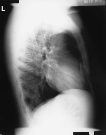

Lateral Position: Chest
With Wheelchair or Cart if Patient Cannot Stand

Patient Position in Wheelchair
• Remove armrests, if possible, or place pillow or other support under smaller patients so that armrests of wheelchair do not superimpose lower lungs.
• Turn patient in wheelchair to lateral position as close to IR as possible.
• Have patient lean forward and place support blocks behind back; raise arms above head and have patient hold on to support bar—keeping arms high.
CR
• CR perpendicular, directed to level of T7 (3 to 4 inches [8 to 10 cm] below level of jugular notch)
Make exposure at end of second full inspiration.
NOTE: Always attempt to have patient sit completely erect in wheelchair or on cart if possible. However, if the patient's condition does not allow this, the head end of the cart can be raised as nearly erect as possible with a radiolucent support behind the back (Fig. 2-63). All attempts should be made to get patient as nearly erect as possible.


AP Projection: Chest
Supine or Semierect (in Department or as Bedside Portable)

 inches [4 to 5 cm] above shoulders).
CR
• CR angled caudad to be perpendicular to long axis of sternum (generally requires ± 5° caudad angle, to prevent clavicles from obscuring the apices)
• CR to level of T7, 3 to 4 inches (8 to 10 cm) below jugular notch
Make exposure at end of second full inspiration.
NOTES: Crosswise IR placement is recommended for large or hypersthenic or broad-chested patients to minimize chance of lateral cutoff. This requires accurate CR alignment with center of IR with only minimal caudal angle to prevent grid cutoff if grid is used.
For semierect position, use 72-inch (183-cm) SID if possible. Always place markers on the IR or label the image to indicate the SID used; also indicate the projections obtained, such as AP supine or AP semierect.


Lateral Decubitus Position (AP Projection): Chest

Patient Position
• Cardiac board on the cart or radiolucent pad under patient
• Patient lying on right side for right lateral decubitus and on left side for left lateral decubitus (see Notes)
• Patient's chin extended and both arms raised above head to clear lung field; back of patient firmly against IR; cart secured to prevent patient from moving forward and possibly falling; pillow under patient's head
• Knees flexed slightly and coronal plane parallel to IR with no body rotation
CR
• CR horizontal, directed to center of IR, to level of T7, 3 to 4 inches (8 to 10 cm) inferior to level of jugular notch. A horizontal beam must be used to show air-fluid level or pneumothorax.
Some department protocols state that the head be 10° lower than the hips to reduce the apical lift caused by the shoulder, allowing the entire chest to remain horizontal (requires support under hips).
NOTES: Place appropriate decub marker and R or L to indicate which side of chest is down.
Radiograph may be taken as a right or left lateral decubitus. To produce the most diagnostic images, both lungs should be included on the image. For possible fluid in the pleural cavity (pleural effusion), the suspected side should be down. Do not cut off that side of the chest. The anatomic side marker must correspond with the patient's left or right side of the body. The marker must be placed on the IR before exposure. It is unacceptable practice to indicate the side of the body either digitally or with a marking pen after the exposure.
For possible small amounts of air in the pleural cavity (pneumothorax), the affected side should be up, and care must be taken not to cut off this side of the chest.


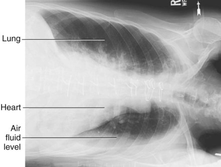
AP Lordotic Projection: Chest

CR
If patient is weak and unstable or is unable to assume the erect lordotic position, an AP semiaxial projection may be taken with the patient in a supine position (Fig. 2-71). Shoulders are rolled forward and arms positioned as for lordotic position. The CR is directed 15° to 20° cephalad, to the midsternum.
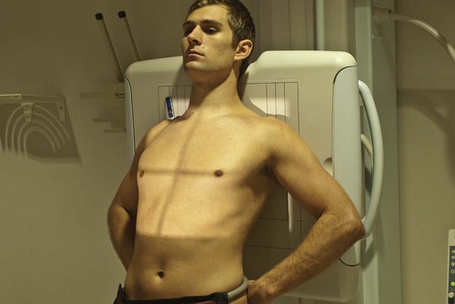


Anterior Oblique Positions—rao and Lao: Chest

Patient Position
• Patient erect, rotated 45° with left anterior shoulder against IR for LAO and 45° with right anterior shoulder against IR for RAO (see Notes for 60° LAO)
• Patient's arm flexed nearest IR and hand placed on hip, palm out
• Opposite arm raised to clear lung field and hand rested on head or on chest unit for support, keeping arm raised as high as possible
CR
• CR perpendicular, directed to level of T7 (7 to 8 inches [8 to 10 cm] below level of vertebra prominens)
• CR midway between midsagittal plane and lateral margin of thorax
Make exposure at end of second full inspiration.
NOTES: For anterior obliques, the side of interest generally is the side farthest from the IR. Thus, the RAO provides the best visualization of the left lung.
Certain positions for studies of the heart and great vessels require oblique positions with an increase in rotation of 45° to 60°. See Figs 2-77 and 2-78.
Less rotation (15° to 20°) may be valuable for better visualization of the various areas of the lungs for possible pulmonary disease.

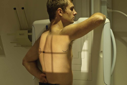
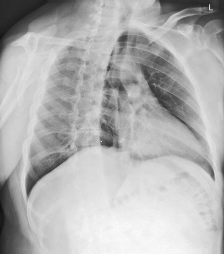
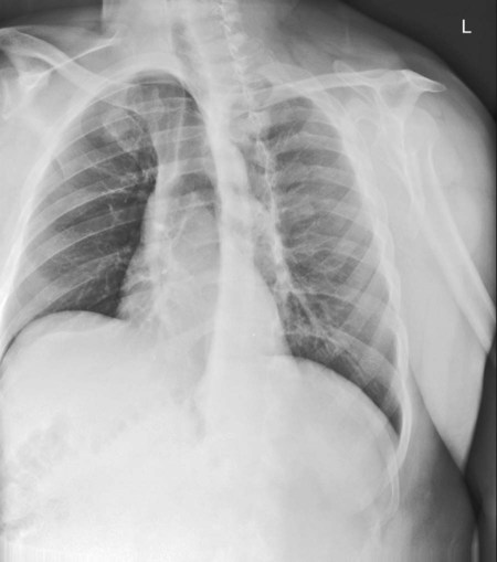


Posterior Oblique Positions—rpo and Lpo: Chest

CR
• CR perpendicular, to level of T7
• CR midway between midsagittal plane and lateral margin of thorax


Lateral Position: Upper Airway

Part Position
• Position patient to center upper airway to CR and to center of IR (larynx and trachea lie anterior to cervical and thoracic vertebrae).
• Rotate shoulders posteriorly with arms hanging down and hands clasped behind back.
• Raise chin slightly and have patient look directly ahead.
• Adjust IR height to place top of IR at level of external auditory meatus (EAM), which is the opening of the external ear canal. (See later if area of primary interest is the trachea rather than the larynx.)
CR
• CR perpendicular to center of IR at level of C6 or C7, midway between the laryngeal prominence of the thyroid cartilage and the jugular notch
Make exposure during a slow, deep inspiration to ensure filling trachea and upper airway with air.
Centering and exposure for distal larynx and trachea region
If the distal larynx and upper trachea and midtrachea are the primary areas of interest, the IR and CR should be lowered to place the CR at the upper jugular notch (T1-2) with exposure factors approximately those for a lateral chest.
Evaluation Criteria
• Centering for the neck region (larynx and proximal trachea) should include the EAM at the upper border of the image and T2 or T3 on the lower border. If the distal larynx and trachea is the primary area of interest, centering should be lower to include the area from C3 to T4 or T5 on the image. • The shadows of the shoulders should be primarily posterior to and should not superimpose the area of the trachea. • Collimation borders should appear on both sides with ideally only minimal (≤ inch) borders on top and bottom.


AP Projection: Upper Airway

Part Position
• Align midsagittal plane with CR and with midline of grid or table.
• Raise chin so that acanthiomeatal line is perpendicular to the IR (line from the acanthion or area directly under the nose and the meatus or EAM); have patient look directly ahead.
• Adjust the IR height to place top of IR about 1 or  inches (3 to 4 cm) below EAM (see Note for explanation of centering).
CR
Make exposure during a slow, deep inspiration to ensure filling of trachea and upper airway with air.
Centering for upper airway and trachea
Centering for this AP projection is similar to that of the lateral distal larynx and upper trachea position described on the previous page because the most proximal area of the larynx is not visualized on the AP as a result of the superimposed base of the skull and mandible. Therefore, more of the trachea can be visualized.
Evaluation Criteria
• The larynx and trachea from C3 to T4 should be filled with air and visualized through the spine. • The area of the proximal cervical vertebrae (the lower margin of the shadow of the superimposed mandible and base of skull) to the midthoracic region should be included.
Position (see previous Notes):
• No rotation should occur, as evidenced by the symmetric appearance of the sternoclavicular joints. • The mandible should superimpose the base of the skull with the spine aligned with the center of the film. • Collimation borders should appear on both sides with ideally only minimal (≤ inch) borders on top and bottom. • The collimation field (CR) should be centered to the area of T1-2.


Radiographs for Critique
Each of the following chest radiographs demonstrates certain errors that required a repeat radiograph. These as well as additional chest radiographs for critique are also available as part of the accompanying audiovisuals and instructor's manual.
Critique these radiographs for errors in one or more of the five categories as described in the textbook and as outlined on the right. As a starting critique exercise, place a check in each category that demonstrates a repeatable error for that radiograph.
Answers are provided in Appendix at the end of this textbook.


| RADIOGRAPHS | |||||
| A | B | C | D | E | |
| 1. Anatomy Demonstrated | ______ | ______ | ______ | ______ | ______ |
| 2. Positioning | ______ | ______ | ______ | ______ | ______ |
| 3. Collimation and CR | ______ | ______ | ______ | ______ | ______ |
| 4. Exposure | ______ | ______ | ______ | ______ | ______ |
| 5. Markers | ______ | ______ | ______ | ______ | ______ |