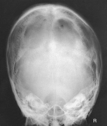
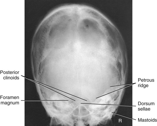
PA Axial Projection: Skull Series
Haas Method
This is an alternative projection for patients who cannot flex the neck sufficiently for AP axial (Towne). It results in magnification of the occipital area but in lower doses to facial structures and the thyroid gland.
This projection is not recommended when the occipital bone is the area of interest because of excessive magnification.


 inches (4 cm) superior to the nasion.
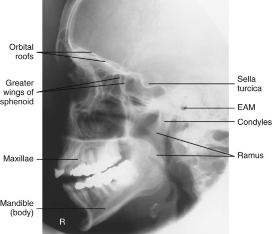
Lateral Position—Right or Left Lateral: Facial Bones
• Rest lateral aspect of head against table or upright imaging device surface, with side of interest closest to IR.
• Adjust head into a true lateral position and oblique body as needed for patient's comfort. (Palpate external occipital protuberance posteriorly and nasion or glabella anteriorly to ensure that these two points are equidistant from tabletop.) Place support sponge under chin if needed.
• Align IPL perpendicular to IR.
• Adjust chin to bring IOML perpendicular to front edge of IR.


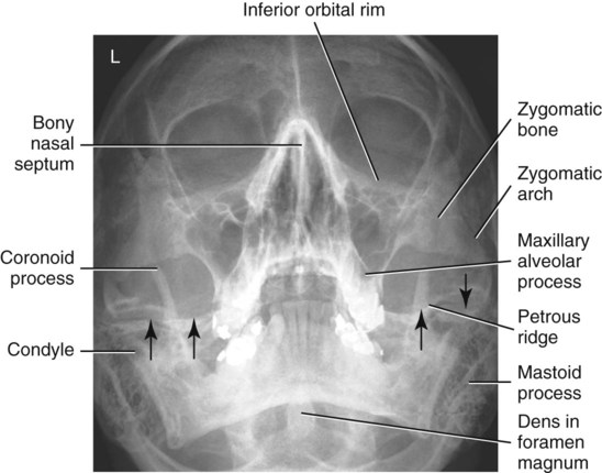
Parietoacanthial Projection: Facial Bones
Waters Method

• Extend neck, resting chin against table/upright imaging device surface.
• Adjust head until MML is perpendicular to plane of IR. OML forms a 37° angle with the table/imaging device surface.
• Position MSP perpendicular to midline of grid or table/imaging device surface, preventing rotation or tilting of head. (One way to check for rotation is to palpate the mastoid processes on each side and the lateral orbital margins with the thumb and fingertips to ensure that these lines are equidistant from the tabletop.)


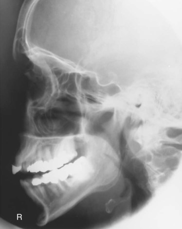
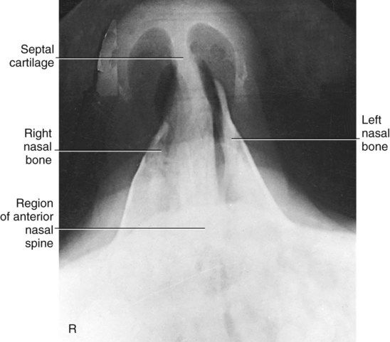
Lateral Position: Nasal Bones

• Minimum SID—40 inches (102 cm)
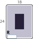
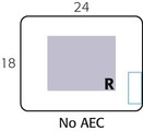
• IR size—18 × 24 cm (8 × 10 inches), crosswise (split*)
• Digital systems—60 to 70 kV range
• Automatic exposure control (AEC) not recommended because of small exposure field
• Rest lateral aspect of head against the table/upright imaging device surface, with side of interest closest to IR.
• Position nasal bones to center of IR.
• Adjust head into a true lateral position and oblique body as needed for patient's comfort (place sponge block under chin if needed).
• Align MSP parallel with a table/upright imaging device surface.
• Align IPL perpendicular to table/upright imaging device surface.
 inch (1.25 cm) inferior to nasion.


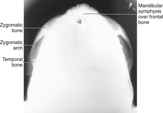
SMV Projection: Zygomatic Arches
• Align CR perpendicular to IR (see Notes).
• Center CR midway between zygomatic arches, at a level  inches (4 cm) inferior to mandibular symphysis.
Suspend respiration during exposure.
NOTES: If patient is unable to extend neck adequately, angle CR perpendicular to IOML. If equipment allows, IR should be angled to maintain CR/IR perpendicular relationship (see Fig. 11-140, inset).
This position is very uncomfortable for patients; complete the projection as quickly as possible.

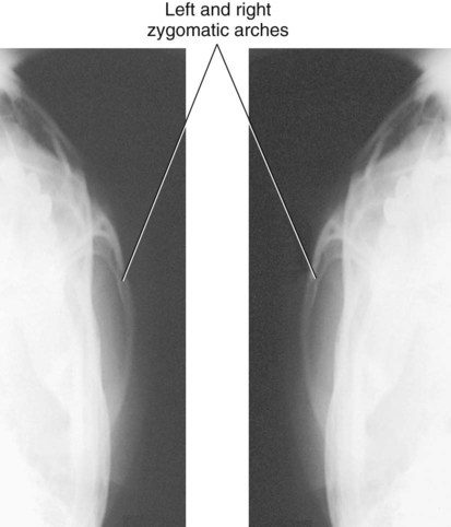
Oblique Inferosuperior (Tangential) Projection: Zygomatic Arches

• Align CR perpendicular to IR and IOML (see Notes).
• Center CR to zygomatic arch of interest (CR skims mandibular ramus, passes through arch, and skims parietal eminence on the downside).
• Adjust IR so it is parallel to IOML and perpendicular to CR.
NOTES: If patient is unable to extend neck sufficiently, angle CR perpendicular to IOML. If equipment allows, IR should be angled to maintain CR/IR perpendicular relationship.
This position is very uncomfortable for the patient; complete the projection as quickly as possible.


AP Axial Projection: Zygomatic Arches
Modified Towne Method
• Angle CR 30° caudad to OML or 37° to IOML (see Note).
• Center CR to 2.5 cm (1 inch) superior to glabella (to pass through midarches) at level of the gonion.
Suspend respiration during exposure.
NOTE: If patient is unable to depress the chin sufficiently to bring OML perpendicular to IR, IOML can be placed perpendicular instead and CR angle increased to 37° caudad. This positioning maintains the 30° angle between OML and CR and demonstrates the same anatomic relationships. (A 7° difference is noted between OML and IOML.)


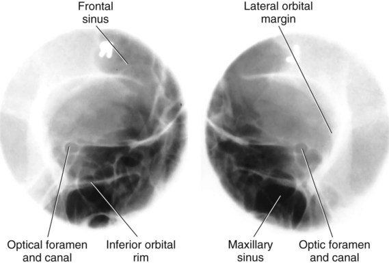
Parieto-Orbital Oblique Projection: Optic Foramina
Rhese Method
• As a starting reference, position patient's head in a prone position with MSP perpendicular to IR. Adjust flexion and extension so that AML is perpendicular to IR. Adjust the patient's head so that the chin, cheek, and nose touch the table/upright imaging device surface.
• Rotate the head 37° toward the affected side. The angle formed between MSP and plane of IR measures 53°. (An angle indicator should be used to obtain an accurate angle of 37° from CR to MSP.)


Axiolateral Oblique Projection: Mandible

• Minimum SID—40 inches (102 cm)
• IR size—18 × 24 cm (8 × 10 inches), crosswise
• Grid (often performed nongrid)
Remove all metallic or plastic objects from head and neck. Patient position is erect or recumbent. If supine for trauma patients, place IR on wedge sponge to minimize object image receptor distance (OID) (see Fig. 11-152), or position IR (and grid if used) lengthwise for horizontal beam trauma position (see Fig. 11-154).
• Place head in a true lateral position, with side of interest against IR.
• If possible, have patient close mouth and bring teeth together.
• Extend neck slightly to prevent superimposition of the gonion over the cervical spine.
• Rotate head toward IR to place the mandibular area of interest parallel to IR. The degree of obliquity depends on which section of the mandible is of interest.
• Head in true lateral position best demonstrates ramus.
• 30° rotation toward IR best demonstrates body.
• 45° rotation best demonstrates mentum.
• 10° to 15° rotation best provides a general survey of the mandible.
• Three methods are suggested for demonstrating the specific region of the mandible of interest (side closest to IR) without superimposing the opposite side:
1. Angle CR 25° cephalad from IPL; for the horizontal beam trauma position, angle CR an additional 5° to 10° posteriorly.
2. Employ a combination of tilt on the head and CR angle not to exceed 25° (e.g., angle the tube 10° and add 15° of head tilt).
3. Employ 25° of head tilt toward IR, and use perpendicular CR.


PA or PA Axial Projection: Mandible

• PA: Align CR perpendicular to IR, centered to exit at junction of lips. For trauma patients, this position is best performed supine.
• Optional PA axial: Angle CR 20° to 25° cephalad, centered to exit at acanthion.


AP Axial Projection: Mandible
Towne Method

• Rest patient's posterior skull against table/upright imaging device surface.
• Tuck chin, bringing OML perpendicular to IR, or place IOML perpendicular and add 7° to CR angle (see Note).
• Align MSP perpendicular to midline of grid or table/upright imaging device surface to prevent head rotation or tilt.


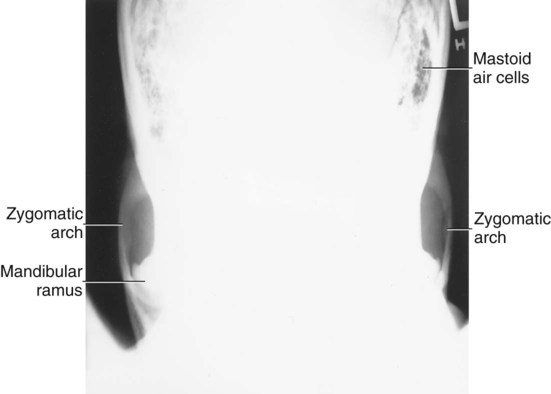
SMV Projection: Mandible

Remove all metallic or plastic objects from head and neck. Patient position is erect or supine (erect preferred, if patient's condition allows). Erect may be done with an erect table or an upright imaging device (see Fig. 11-163, inset).
 inches (4 cm) inferior to mandibular symphysis.


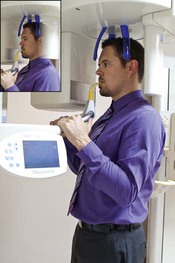
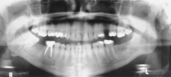
Orthopantomography—Panoramic Tomography: Mandible

• Remove all metal, plastic, and other removable objects from head and neck.
• Explain to patient how tube and IR rotate and the time span needed for exposure.
• Guide patient into unit, resting patient's chin on bite-block.
• Position patient's body, head, and neck as demonstrated in Figs. 11-168 and 11-169. Do not allow head and neck to stretch forward; have patient stand in close, with spine straight and hips forward.
• Adjust height of chin rest until IOML is aligned parallel with floor. The occlusal plane (plane of biting surface of teeth) declines 10° from posterior to anterior.
• Align MSP with vertical center line of chin rest.
• Position bite-block between patient's front teeth (see Note).
• Instruct patient to place lips together and position tongue on roof of mouth.
• CR is fixed and directed slightly cephalic to project anatomic structures, positioned at the same height, on top of one another.
The first digital orthopantomography was developed in 1995. Since 1997, digital orthopantomography systems have been replacing the analog or systems. These systems do not require a cassette or chemical processing of images. They use charged couple device technology or a photostimulable phosphor to convert the analog signal into a digitized image. A key advantage of digital orthopantomography over film-based systems is increased exposure latitude and fewer repeat studies. This leads to reduced costs and patient exposure (Figs. 11-166 and 11-169).
Advantages of Orthopantomography Compared with Conventional Mandible Positioning
• More comprehensive image of the mandible, TMJs, surrounding facial bones, and teeth
• Low patient radiation dose (slit collimation reduces exposure to eyes and thyroid gland)
• Convenience of examination for patient (one position provides the panoramic view of entire mandible)
• Ability to image the teeth in a patient who cannot open the mouth or when the oral cavity is restricted


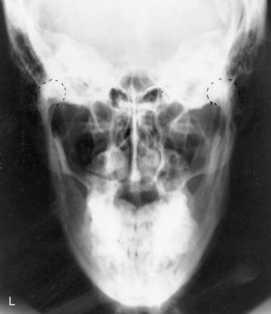
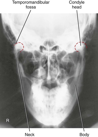
AP Axial Projection: TMJs
Modified Towne Method
WARNING: Opening the mouth should not be attempted with possible fracture.
• Rest patient's posterior skull against table/upright imaging device surface.
• Tuck chin, bringing OML perpendicular to table/imaging device surface or bringing IOML perpendicular and increasing CR angle by 7°.
• Align MSP perpendicular to midline of the grid or the table/upright imaging device surface to prevent head rotation or tilt.
• Angle CR 35° caudad from OML or 42° from IOML.
• Direct CR 3 inches superior to the nasion. Center IR to projected CR.
Suspend respiration during exposure.
NOTE 1: Some departmental protocols indicate that these projections should be taken in both closed mouth and open mouth positions for comparison purposes when patient's condition allows.
NOTE 2: An additional 5° increase in CR may best demonstrate the TM fossae and TMJs.

 inches (4 cm) superior to upside EAM (to pass through downside TMJ).
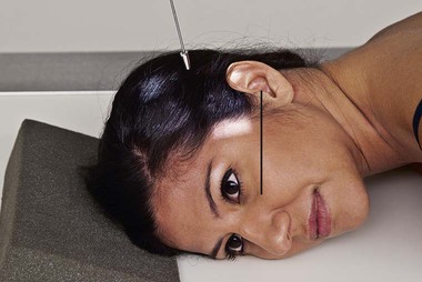

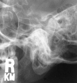
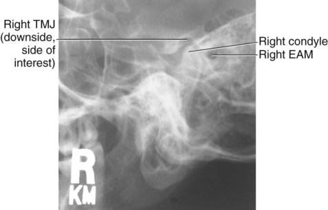
Axiolateral Projection: TMJ
Schuller Method
 inch (1.3 cm) anterior and 2 inches (5 cm) superior to upside EAM.


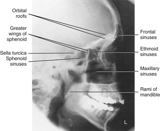
Lateral Position—Right or Left Lateral: Sinuses

• Place lateral aspect of head against table/upright imaging device surface, with side of interest closest to IR.
• Adjust head into true lateral position, moving body in an oblique direction as needed for patient's comfort (MSP parallel to IR).
• Align IPL perpendicular to IR (ensures no tilt).
• Adjust chin to align IOML perpendicular to front edge of IR.
• Align horizontal CR perpendicular to IR.
• Center CR to a point midway between outer canthus and EAM.
Suspend respiration during exposure.
NOTES: To visualize air-fluid levels, an erect position with a horizontal beam is required. Fluid within the paranasal sinus cavities is thick and gelatin-like, causing it to cling to the cavity walls. To visualize this fluid, allow a short time (at least 5 minutes) for the fluid to settle after patient's position has been changed (i.e., from recumbent to erect).
If patient is unable to be placed in the upright position, the image may be obtained with the use of a horizontal beam, similar to trauma lateral facial bones, as described in Chapter 15.

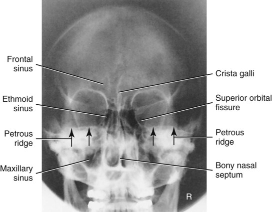
PA Projection: Sinuses
Caldwell Method

• Place patient's nose and forehead against upright imaging device or table with neck extended to elevate OML 15° from horizontal. A radiolucent support between forehead and upright imaging device or table may be used to maintain this position. CR remains horizontal. (See alternative method if imaging device can be tilted 15°.)
• Align MSP perpendicular to midline of grid or upright imaging device surface.
NOTE: To assess air-fluid levels accurately, CR must be horizontal, and the patient must be erect.
ALTERNATIVE METHOD: An alternative method if the imaging device can be tilted 15° is shown (Fig. 11-186, inset). The patient's forehead and nose can be supported directly against the imaging device with OML perpendicular to imaging device surface and 15° to horizontal CR.


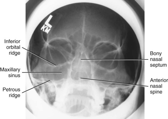
Parietoacanthial Projection: Sinuses
Waters Method

• Extend neck, placing chin and nose against table/upright imaging device surface.
• Adjust head until MML is perpendicular to IR; OML forms a 37° angle with plane of IR.
• Position MSP perpendicular to midline of grid or table/upright imaging device surface.


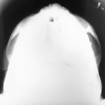
SMV Projection: Sinuses

• CR directed perpendicular to IOML (see Notes)
• CR centered midway between angles of mandible, at a level  to 2 inches (4 to 5 cm) inferior to mandibular symphysis
Suspend respiration during exposure.
NOTES: If patient is unable to extend neck sufficiently, angle the tube from horizontal as needed to align CR perpendicular to IOML.
This position is very uncomfortable for the patient; have all factors set before positioning the patient, and complete the projection as quickly as possible.


Parietoacanthial Transoral Projection: Sinuses
Open Mouth Waters Method

• Extend neck, placing chin and nose against table/upright imaging device surface.
• Adjust head until OML forms 37° angle with IR (MML is perpendicular with mouth closed).
• Position MSP perpendicular to the midline of grid or table/upright imaging device surface; ensure no rotation or tilt.
• Instruct patient to open mouth by instructing to “drop jaw without moving head.” (MML is no longer perpendicular.)


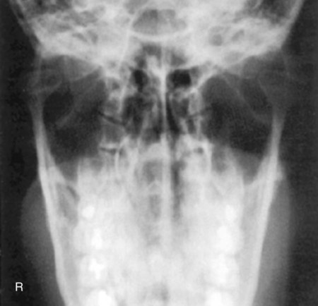
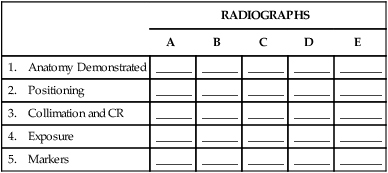
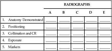
Radiographs for Critique—Cranium
Each of these skull radiographs demonstrates at least one repeatable error. See whether you can critique each of these radiographs based on the categories as described in the textbook and as outlined on the right. As a starting critique exercise, place a check mark in each category that demonstrates a repeatable error for that radiograph.
Answers are provided in the Appendix at the end of this textbook.
| RADIOGRAPHS | |||||
| A | B | C | D | E | |
| 1. Anatomy Demonstrated | ______ | ______ | ______ | ______ | _______ |
| 2. Positioning | ______ | ______ | ______ | ______ | _______ |
| 3. Collimation and CR | ______ | ______ | ______ | ______ | _______ |
| 4. Exposure | ______ | ______ | ______ | ______ | _______ |
| 5. Markers | ______ | ______ | ______ | ______ | _______ |


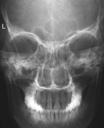
Radiographs for Critique—Facial Bones
NOTE: Remember, CR must be horizontal and the patient erect to demonstrate air-fluid levels within the paranasal sinuses.
Students should determine whether they can critique each of these five radiographs based on the categories as described in the textbook and as outlined on the right. As a starting critique exercise, place a check in each category that demonstrates a repeatable error for that radiograph.
Answers are provided in the Appendix at the end of this textbook.
| RADIOGRAPHS | |||||
| A | B | C | D | E | |
| 1. Anatomy Demonstrated | ______ | ______ | ______ | ______ | ______ |
| 2. Positioning | ______ | ______ | ______ | ______ | ______ |
| 3. Collimation and CR | ______ | ______ | ______ | ______ | ______ |
| 4. Exposure | ______ | ______ | ______ | ______ | ______ |
| 5. Markers | ______ | ______ | ______ | ______ | ______ |


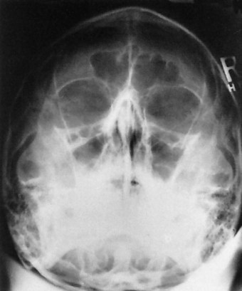
Radiographs for Critique—Sinuses
Students should determine whether they can critique each of these four radiographs based on the categories as described in the textbook and as outlined on the right. As a starting critique exercise, place a check in each category that demonstrates a repeatable error for that radiograph.
Answers are provided in the Appendix at the end of this textbook.
| RADIOGRAPHS | |||||
| A | B | C | D | E | |
| 1. Anatomy Demonstrated | ______ | ______ | ______ | ______ | ______ |
| 2. Positioning | ______ | ______ | ______ | ______ | ______ |
| 3. Collimation and CR | ______ | ______ | ______ | ______ | ______ |
| 4. Exposure | ______ | ______ | ______ | ______ | ______ |
| 5. Markers | ______ | ______ | ______ | ______ | ______ |


