Dental Implants
Few advances in dentistry have been as remarkable as the use of dental implants (Fig. 32-1) to restore orofacial form and function. Implant technology has enabled the dentist to help affected patients regain the ability to chew normally and function without embarrassment. With the application of precise surgical and prosthodontic techniques, implant-facilitated restorations allow for a very predictable prosthodontic successful rehabilitation of a broad spectrum of patients with very challenging needs. The predictable results of contemporary implant systems derive, in part, from increasingly sophisticated imaging techniques used in all phases of implant treatment. These imaging modalities contribute information for every stage of the treatment, extending from presurgical diagnosis and treatment planning through surgical placement and postoperative assessment of the implant, to the prosthetic restoration and long-term surveillance phase.
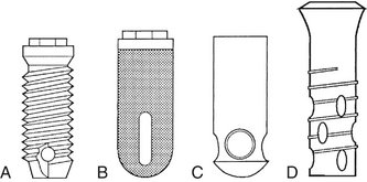
FIG. 32-1 Four common types of root-form implant fixtures. A, Brånemark. B, IMZ. C, Integral. D, ITI.
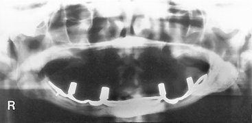
Acceptance of dental implantology as an integral part of conventional practice makes it necessary for the general dentist to be knowledgeable of implant imaging techniques and their clinical application. With the exception of the occasional subperiosteal, blade, and transosteal implant systems (Figs. 32-2 and 32-3), dental implants used today are almost exclusively root-form devices (see Fig. 32-1) embedded within the jaw bone (endosseous implants). The focus of this chapter is not only to provide information regarding the various imaging technologies available but also their specific application and the potential information that each can provide to facilitate the placement of endosseous implant restorations.
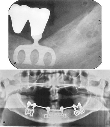
FIG. 32-2 A, Blade implant integrated with bone to support a fixed bridge (periapical radiograph of a mandibular molar). B, Three blade implants integrated with bone using common abutments to support a mandibular denture region. (A courtesy Krishan Kapur, DDS, Los Angeles, Calif.)
Diagnostic Imaging for Dental Implants
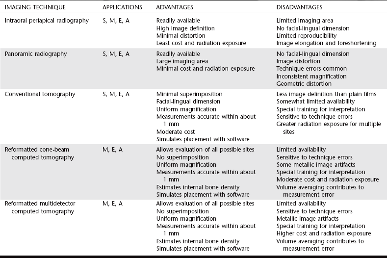
Basic imaging, such as panoramic and periapical radiographs, are generally useful and cost-effective but do not provide the cross-sectional visualization or interactive image analysis that can be obtained with more sophisticated imaging techniques. The various imaging techniques can be applied to various phases of the surgical and restorative procedures (Table 32-1). The selection of a specific imaging technique should be based on the technique best suited to provide the information required by the implant team—the restorative dentist, surgeon, and radiologist (Table 32-2).
TABLE 32-1
| STAGE OF TREATMENT | TIME (mo) | RADIOGRAPHIC PROCEDURES |
| Treatment planning | −1 | PA, pan, tomo, CBCT/MDCT, ceph |
| Surgery (placement) | 0 | PA, pan, tomo, CBCT/MDCT, ceph for correction of problems |
| Healing | 0-3 | PA, pan, tomo, CBCT/MDCT, ceph for correction of problems |
| Remodelling | 4-12 | PA, pan |
| Maintenance (without problems) | 13+ | PA, pan, (following approximately every 3 years) |
| Complications | Anytime | PA, pan, CBCT/MDCT (as indicated) |
PA, Periapical; pan, panoramic radiography; tomo, conventional tomography; CBCT, cone-beam computed tomography; MDCT, multidetector computed tomography; ceph, lateral/lateral-oblique cephalometric radiography.
Imaging Techniques
The ideal imaging technique for dental implant care should have several essential characteristics, including the ability to visualize the implant site in the mesiodistal, facial-lingual, and superoinferior dimensions; the ability to allow reliable, accurate measurements; a capacity to evaluate trabecular bone density and cortical thickness; a capacity to correlate the imaged site with the clinical site; reasonable access and cost to the patient; and minimal radiation risk. Usually a combination of radiographic techniques is used. Available radiographic techniques include intraoral radiography (film and digital), cephalometric radiography, panoramic radiography, and conventional tomography, as well as cone-beam and multidetector computed tomography (CBCT, MDCT). The following is a review of these imaging techniques as applied to dental implant case management.
INTRAORAL RADIOGRAPHY
Intraoral images may be acquired on analog film or as digital images. Periapical and occlusal radiographic films provide images with superior resolution and sharpness. Periapical radiographs commonly are used to evaluate the status of adjoining teeth and remaining alveolar bone in the mesiodistal dimension. They also have been used for determining vertical height, architecture, and bone quality (bone density, amount of cortical bone, and amount of trabecular bone). Although readily available and relatively inexpensive, periapical radiography has geometric and anatomic limitations. Periapical radiographs, made on a dentate arch, typically are made with the paralleling technique, creating an image with minimal foreshortening and elongation (Fig. 32-4). Because of variations in the morphology of the residual edentulous alveolar ridge (Fig 32-5), the ridge may not have the same “long axis” as a tooth. Thus the position of the image receptor may not result in an accurate display of the height of the alveolar ridge as a result of image foreshortening and elongation. Also, it frequently is not possible to place the image receptor either superior or inferior enough to capture an image of the entire maxillary or mandibular ridge. It is reported that 25% of mandibular periapical radiographs do not demonstrate the mandibular canal. In cases when the canal was identifiable, only 53% of measurements from the alveolar crest to the superior wall of the mandibular canal were accurate within 1 mm.
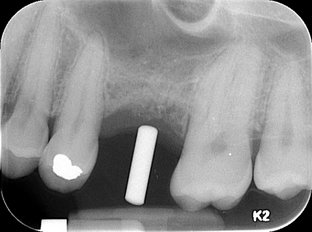
FIG. 32-4 An intraoral periapical radiograph of a potential implant site. The imaging stent indicates the desired axis of insertion.
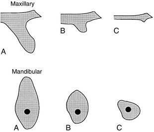
FIG. 32-5 Patterns of bone morphology in the anterior maxilla (above) and posterior mandible (below) in potential implant therapy patients. Minimal resorption (A), moderate resorption (B), and severe resorption (C) of alveolar bone. (Modified from Brånemark P-I, Zarb GA, Albrektsson T: Tissue-integrated prostheses: osseointegration in clinical dentistry, Chicago, 1985, Quintessence.)
Because periapical radiographs are unable to provide any cross-sectional information, occlusal radiographs are used on occasion to determine the facial-lingual dimensions of the mandibular alveolar ridge. Although somewhat useful, the occlusal image records only the widest portion of the mandible, which typically is located inferior to the alveolar ridge. This may give the clinician the impression that more bone is available in the cross-sectional (facial-lingual) dimension than actually exists. The occlusal technique is not useful in imaging the maxillary arch because of anatomic limitations.
LATERAL AND LATERAL-OBLIQUE CEPHALOMETRIC RADIOGRAPHY
Lateral cephalometric radiography provides an image of known magnification (usually 7% to 12%) that documents axial tooth inclinations and the dentoalveolar ridge relationships in the midline of the jaws. The soft tissue profile also is apparent on this film and can be used to evaluate profile alterations after prosthodontic rehabilitation. This projection can provide a cross-sectional view of only the maxillary and mandibular midline. Images of nonmidline structures are superimposed on the contralateral side, complicating the evaluation of other implant sites. Occasionally, lateral-oblique cephalometric radiography is used with one side of the mandibular body positioned parallel to the film cassette. Image magnification on these views is not predictable because the body of the mandible is not the same distance from the film as is the rotation center of the cephalostat (used to calculate object-film distance for image magnification values). Thus measurements made from these radiographs are not reliable. In general, cephalometric radiographs have significant limitations but may be useful in placement of some implants near the midline for overdentures.
PANORAMIC RADIOGRAPHY
Although the resolution and sharpness of panoramic radiographs are less than those of intraoral radiographs, panoramic projections certainly provide a broader visualization of the jaws and adjoining anatomic structures. Panoramic radiography units are widely available, making this imaging technique very useful and popular as a screening and assessment instrument. This technique is useful in making preliminary estimations of crestal alveolar bone and cortical boundaries of the mandibular canal, maxillary sinus, and nasal fossa (Fig. 32-6).
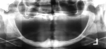
FIG. 32-6 Evaluation of potential implant sites by panoramic radiograph; note the severe atrophy of the maxillary and mandibular alveolar process.
Information acquired from panoramic radiographs must be applied judiciously because this technique has significant limitations as a definitive presurgical planning tool. Angular measurements on panoramic radiographs tend to be accurate, but linear measurements are not. Image size distortion (magnification) varies significantly between films from different panoramic units and even within different areas of the same film. Vertical measurements are unreliable because of foreshortening and elongation of the anatomic structures because the x-ray beam is not perpendicular to the long axis of the anatomic structures or to the plane of the image receptor. The negative vertical angulation of the x-ray beam also causes lingually positioned objects such as mandibular tori to be projected superiorly on the film, resulting in an overestimation of vertical bone height. Furthermore, the anatomic vertical axis varies within the image, particularly in nonmidline areas. Compared with contact radiographs of dissected anatomic specimens, only 17% of panoramic measurements between the alveolar crest and superior wall of the mandibular canal were found to be accurate within 1 mm.
Similarly, dimensional accuracy in the horizontal plane of panoramic radiographs is highly dependent on the position of the structures of interest relative to the central plane of the image layer. The horizontal dimension of images of structures located facial or lingual to the central plane but still within the image layer tends to be minified or magnified. The degree of horizontal size distortion is difficult to ascertain on panoramic radiographs because the shape of the image layer is configured to a population average and the anatomic morphology of only a few individuals conforms totally to that image layer. In summary, horizontal image magnification with panoramic radiographs varies from 0.70 to 2.2 times the actual size, which some manufacturers report as a 1.25 average magnification (at the central plane of the image layer). Errors in patient positioning can further exacerbate measurement error in the horizontal dimension. The deficient dimensional accuracy of the two-dimensional panoramic image is further limited by the lack of any cross-sectional information.
CONVENTIONAL TOMOGRAPHY
Used as an adjunct to screening radiographs, cross-sectional tomograms enhance visualization of the available bone by providing reliable dimensional measurements at proposed implant sites, especially the cross-sectional (facial-lingual) dimension. Tomographic machines were readily available but now are being replaced with CBCT machines. This technique produces a cross-sectional, flat-plane image layer that is perpendicular to the x-ray beam. Images of anatomic structures of interest are relatively sharp, and images of structures outside the image layer are blurred beyond recognition by the motion of the x-ray tube and image receptor. The thickness, orientation, and anatomic location of the image layer can be predetermined and manipulated. To obtain reliable measurements, it is critical that the image layer be a true cross-section of the curve of the alveolar process, rather than oblique. Scout images (usually a submentovertex, occlusal, or panoramic projection) or wax bite registrations or dental models are commonly used to determine the appropriate cross-sectional angulation. The complex (multidirectional) tube motion of current conventional tomographic units minimizes image superimposition and provides fixed, uniform image magnification, thus allowing for accurate measurements. Complex tube motion also permits use of a thicker image layer while retaining diagnostic quality. A thicker image layer is desirable to maximize image contrast, making the identification of structures such as the mandibular canal more predictable. Conventional tomographic images may be acquired as analog films or digital images.
The dimensional accuracy of cross-sectional tomograms is particularly useful in measuring the distance between the alveolar crest and adjacent structures, such as the floor of the nasal fossa, maxillary sinus floor, mandibular canal, mental canal, and inferior mandibular cortex. The appropriate buccal-lingual axis of insertion of the implant may also be assessed preoperatively. Measurements are directly acquired from the images and subsequently corrected by the magnification factor used. As an alternative, acetate overlays with appropriately magnified 1-mm grids may be used with film-based images or on digital monitors when the display is life sized (Fig. 32-7). Published research suggests a measurement error of less than 1 mm in optimal images. Typically, two to three cross-sectional tomographic slices are required to adequately image each intended implant site. Conventional tomography is especially convenient in the planning of single implants or multiple implants within a quadrant (Fig. 32-8).
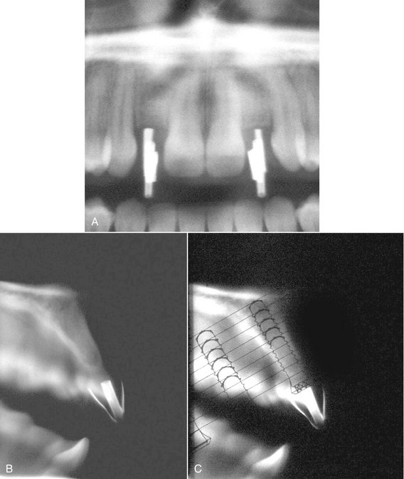
FIG. 32-7 Complex-motion conventional tomographic series of the maxilla. Metal cylinders retained within an acrylic imaging stent are used to indicate the planned implant sites. Foil strips have been placed on the stent to indicate desired buccal and lingual contours of the restoration. A, A scout panoramic radiograph used to orient subsequent tomograms. B, Cross-sectional tomograms appropriate for measuring the height and width of the alveolar ridge, as well as the axial orientation of the proposed implant. C, A clear plastic overlay is placed over the tomogram to visualize implant placement and determine desired length. The overlay is the same magnification as the tomographic image. (Courtesy Oral and Maxillofacial Imaging Center, Baylor College of Dentistry, Dallas, Tex.)
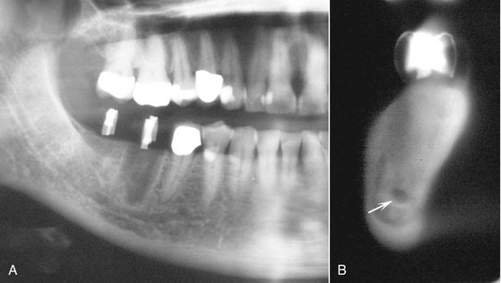
FIG. 32-8 Complex-motion conventional tomographic series of the mandible. Metal cylinders retained within an acrylic imaging stent have been used to indicate the planned implant sites. A, Scout panoramic radiograph used to orient the subsequent tomograms. B, Cross-sectional tomogram appropriate for measuring the height and width of the alveolar ridge and the axial orientation of the proposed implant. Note the mandibular canal (arrow). (Courtesy Oral and Maxillofacial Imaging Center, Baylor College of Dentistry, Dallas, Tex.)
REFORMATTED CONE-BEAM AND MULTIDETECTOR COMPUTED TOMOGRAPHY
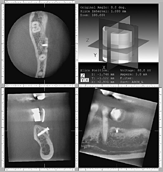
Patients who are edentulous or who are being considered for multiple implants and augmentation procedures may be best imaged with either CBCT or MDCT to investigate all possible implant sites. For traditional MDCT, a lateral scout image of the selected jaw with the necessary alignment corrections for the mandible or maxilla is typically an essential initial step for the MDCT study. The jaws are aligned so that the acquired axial computed tomographic image slices are parallel to the occlusal plane. These axial images are thin (1-2 mm) and overlapping, resulting in approximately 30 axial image slices per jaw. The image information of these sequential axial images can be postprocessed to produce multiple two-dimensional images in various planes, using a computer-based process called multiplanar reformatting (MPR).
CBCT images are acquired with an initial scout image followed by a single revolution imaging sequence. The vertical height of the imaging sequence can be adjusted to include only one jaw, both, or a larger area, especially if the temporomandibular joint needs to be included in the imaged area. MPR processing is also accomplished with the CBCT data.
The reformatted images of both types of computed tomographic data result in three basic image types: axial images with a computer-generated superimposed curve of the alveolar process and the associated reformatted alveolar cross-sectional images and panoramic-like images. An axial image that includes the full contour of the mandible (or maxilla) at a level corresponding to the dental roots is typically selected as a reference for the reformatting process. With use of a computer program, a series of sequential dots on the selected axial scan are connected to develop a customized arch or curve unique for each jaw. The computer program then generates a series of lines perpendicular to the curve of the individual arch. These lines are made at constant intervals (usually 1 to 2 mm) and numbered sequentially on the axial and panoramic (curved linear) images to indicate the position at which each cross-sectional slice will be reconstructed (Figs. 32-9 and Fig. 32-10). Cross-sectional alveolar reconstructions are made perpendicular to the curve, and panoramic (curved linear) reconstructions are made parallel with the curve. Three-dimensional representations may also be constructed in various orientations.
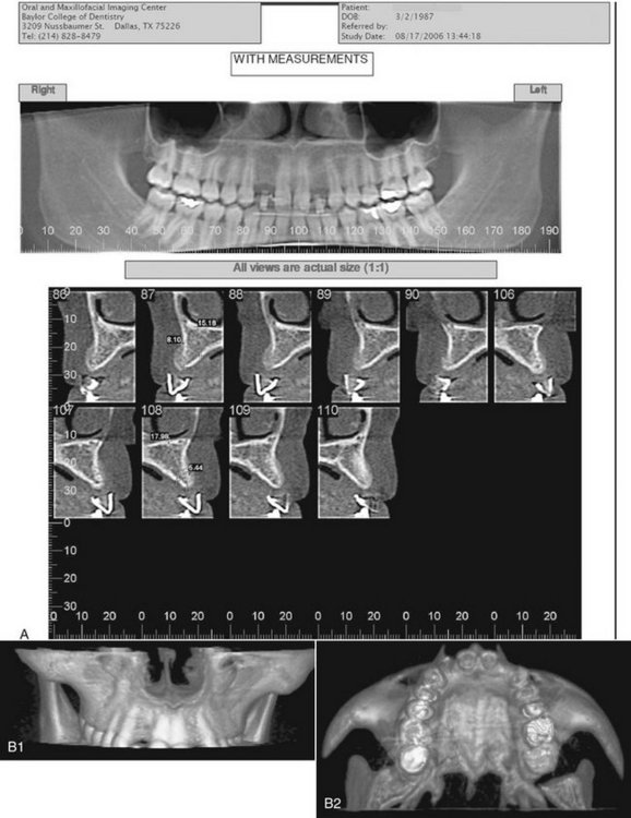
FIG. 32-9 Reformatted cone-beam CT study of the maxilla. A, Panoramic-like curved linear and alveolar cross-sectional reconstructed images using an imaging stent incorporating radiopaque strips to define the buccal and palatal contours of the planned prosthesis. Note the measurements on the cross-section images. B, Three-dimensional reformatted images to visualize the morphology of the intended implant sites. (Courtesy Oral and Maxillofacial Imaging Center, Baylor College of Dentistry, Dallas, Tex.)
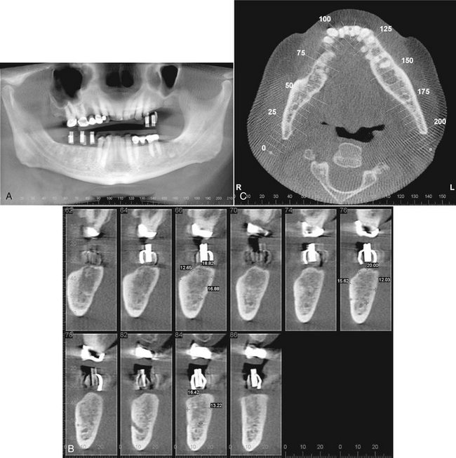
FIG. 32-10 Reformatted cone-beam CT study of the mandible. A, Panoramic-like curved linear reconstructed image. The imaging stent incorporates copper cylinders for the path of insertion and radiopaque strips defining the buccal and lingual contours of the proposed prosthesis. The copper cylinders will allow the imaging stent to be used as a surgical guide when the implants are placed. B, Correlating cross-sectional images. C, Reformatted axial image through the alveolar ridge depicting the panoramic arc and correlated cross-sectional images. (Courtesy Oral and Maxillofacial Imaging Center, Baylor College of Dentistry, Dallas, Tex.)
Such reformatted images provide the clinician with accurate two-dimensional diagnostic information in all three dimensions. Typical computed tomographic studies provide information on the continuity of the cortical bone plates, residual bone in the mandible and maxilla, the relative location of adjoining vital structures, and the contour of soft tissues covering the osseous structures. Studies have reported that 94% of computed tomographic measurements between the alveolar crest and wall of the mandibular canal were accurate within 1 mm. Reformatted images from CBCT data have been shown to be of equivalent measurement accuracy as MDCT data. These reformations are also useful in the planning augmentation procedures such as a sinus lift and can provide an estimate of the internal density. A three-dimensional image can provide a visualization of the overall morphology of the intended implant site.
Reformatted CBCT/MDCT images may be printed as life size on photographic prints or radiographic film. If the study is to be viewed electronically as individual static images on a monitor, a measurement scale is typically incorporated into the image for calibration. Alternatively, the reformatted study may also be viewed with interactive software. The panoramic (curved linear) images are helpful in identifying mesial-distal relationships and noncorticated mandibular canals. However, the quality of the reformatted computed tomographic study depends on the ability of the patient to remain still during image acquisition because movement may produce geometric image distortion. Because of the shorter acquisition times, this is less of an issue with CBCT. Metallic restorations can cause streak image artifacts, but this can be avoided by aligning the jaws so that the acquired axial scans are parallel to the occlusal plane, which sometimes keeps the artifact from obscuring the alveolar crest. Metallic artifacts are less prominent on CBCT by nature of the image acquisition physics. All the images in computed tomographic studies for dental implant studies should be adequately interpreted by an oral and maxillofacial radiologist or other appropriately trained dentist or physician. This is especially important because a rather large anatomic area outside the region of interest is included in the primary images and must be reviewed.
Preoperative Planning
Radiographic visualization of potential implant sites is an important extension of clinical examination and assessment. Radiographs help the clinician visualize the alveolar ridges and adjacent structures in all three dimensions and guide the choice of site, number, size, and axial orientation of the implants. Site selection includes consideration of adjacent anatomic structures such as the incisive and mental foramina, inferior alveolar canal, existing teeth, nasal fossae, and maxillary sinuses. Conditions, including retained root fragments, impacted teeth, and any osseous pathoses that could compromise the outcome, must be identified and located relative to the site of the proposed implant.
Diagnostic images of potential implant sites can provide information about the quality and quantity of bone that would be adequate to support the implant fixture. The quality of bone includes assessment of the cortical bone because it is best suited to withstand the functional loading forces of dental implants. There is a greater likelihood of successful osseous integration when there is a thicker cortical bone. A greater number of internal trabeculae per unit area is also advantageous.
Bone quantity is assessed by documenting the height and width of available alveolar bone and the morphology of the ridge. The chances of a successful outcome will increase with a greater amount of bone available for anchorage. A cross-sectional image to document the facial-lingual width and height of the ridge, along with the inclination of the bone contours, is especially useful in the preoperative planning phase. Alveolar ridge width measurements aid in selecting the implant diameter and implant placement to maximally engage cortical bone. Ridge height measurements help select the largest appropriate fixture to maximize anchorage and distribution of masticatory forces. Frequently, morphologic features such as osseous undercuts and ridge concavities that are not immediately apparent on clinical examination become evident with cross-sectional imaging.
Accurate bone measurements are essential for determining the optimal size and length and orientation of the proposed implants. When measurements are made on any image, the fact that the magnification factor of the image might vary with the imaging technique used must be considered. Except for specialized interactive reformatted computed tomography implant programs; all other radiographic images have a magnification factor, which must be taken into account when the dimensions of the bone are calculated. The measurements obtained from the images (usually in millimeters) are divided by the magnification factor for that particular imaging technique. As described earlier, the magnification factor of some techniques may be variable (periapical, panoramic), and thus a constant magnification factor cannot be applied. With dental implant computed tomographic reformatting software, the image is reproduced in the actual size of the jaw without magnification. If the magnification factor is constant, clear plastic overlays with 1-mm grids or diagrams of available implant sizes already corrected for the specific magnification factor can be used directly on printed images or on the viewing monitor with the image displayed at 1 : 1. The magnification of electronic images can also be calibrated with the measurement tool.
IMAGING STENTS
The clinical utility of presurgical imaging can be enhanced by the use of an imaging stent that helps relate the radiographic image and its information to a precise anatomic location or a potential surgical site. In the case of conventional and computed tomography, an imaging stent also facilitates correlation of the individual image slices to an anatomic location in the scout films. The intended implant sites are identified by markers made of radiopaque spheres or rods (metal, composite resin, or gutta-percha) retained within an acrylic stent (Fig. 32-11; see Fig. 32-7), which the patient wears during the imaging procedure so that images of the markers will be created in the diagnostic images. The imaging stent subsequently may be used as a surgical guide to orient the insertion angle of the guide bur and hence the angle of the implant. For optimal visualization, the width of the markers should be less than the thickness of the conventional tomographic image layer. Diagnostic dentures coated with barium paste may be used during imaging for localization and can also establish the spatial relationships between the anticipated prosthesis and the implant fixtures. Generally, nonmetallic radiopaque markers (gutta-percha, composite resin) are used in computed tomographic imaging because of the image artifacts that would be produced by metal markers. However, some metals scatter less than others. The metallic scatter artifact of some CBCT units appears to be less than that of MDCT units. Existing rootform implants do not produce a significant computed tomographic scatter artifact.
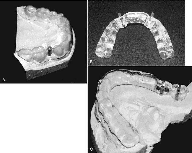
FIG. 32-11 Three examples of imaging stents. A, A vacuum-formed imaging stent with a metal rod to indicate desired axis of insertion. B, A processed stent with metal cylinders marking the implant sites. This can also be used as a surgical stent by inserting the guide bur through the cylinders. C, A processed stent with insertion axis markers, along with a radiopaque strip outlining the buccal and lingual contours of the planned restoration. The stent provides an image of the emergence profile of the restored implant and can also be used as a surgical guide.
INTERACTIVE DIAGNOSTIC SOFTWARE
Several different interactive software packages that can simulate implant orientation and placement on a computer screen before surgery have been developed. They are designed for use on personal computers, typically requiring a Windows (Microsoft, Redmond, Wash.) operating system. Diagnostic software is available for both conventional tomography and reformatted computed tomography. These programs provide an interactive analysis of potential implant sites for bone quantity, quality, and morphology and can simulate the surgical placement of the implant. Visualization of anatomic structures, volumetric analysis for bone grafts, and mechanical analysis of structural forces during restoration are also within the capability of the software packages (Fig. 32-12).
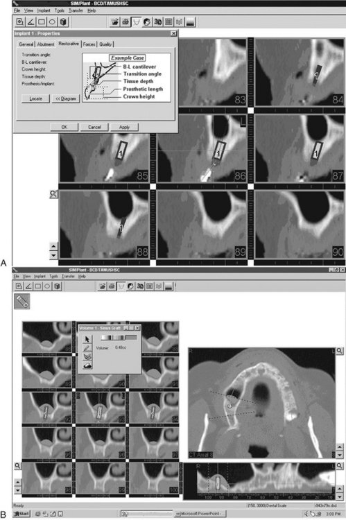
FIG. 32-12 SIMPlant (Materialise, New Berne, Md.) interactive software. A, Simulation of implant placement and predicted restorative dimensions are displayed on cross-sectional images. B, The volume of bone grafting material for a sinus lift procedure is predicted in a case with inadequate alveolar ridge height.
SELECTING DIAGNOSTIC IMAGING FOR PREOPERATIVE PLANNING
A good starting point would be to proceed with a panoramic image and possibly intraoral radiographs if greater image detail is required of any particular region of interest. These survey radiographs would help determine whether the patient is a good candidate for implant procedures. For instance, if there is a pathologic lesion in the planned implant site or if there is obviously inadequate vertical dimension from severe atrophy of the alveolar ridges, there is no sense in proceeding with more expensive imaging procedures such as conventional or computed tomography. If the initial scout films reveal reasonable potential implant sites, then either conventional or computed tomography can be used to obtain cross-sectional image slices of these sites (see Table 32-2 and Fig. 32-13). Generally, if images are required of all of the maxilla and mandible to evaluate possible implant sites, then computed tomography would be the best modality. If potential sites are restricted to a few selected regions, then conventional tomography would be a suitable choice. However, the ease of acquisition and relatively low radiation risk of CBCT makes this technique a very viable alternative study even for single implants.
Intraoperative and Postoperative Assessments
Intraoral and panoramic radiographs usually are adequate for both intraoperative and postoperative assessments (Fig. 32-14). Intraoperative imaging may be required to confirm correct placement of the implant or to locate a lost implant (Fig. 32-15). The two aspects that are usually assessed with time after implant placement are the alveolar bone height around the implant and the appearance of the bone immediately adjacent to and surrounding the implant. If threaded rootform fixtures have been placed, the optimal radiographic image must separate the threads for best visualization. This may not always be a predictable procedure because the exact angulation of the implant is not known. The angulation of the x-ray beam must be within 9 degrees of the long axis of the fixture to open the threads on the image on most threaded fixtures (Fig. 32-16). Angular deviations of 13 degrees or more result in complete overlap of the threads. In general, periapical radiographs are appropriate for longitudinal assessments. However, in evaluating the bone height around an implant, an effort should be made to reproduce the vertical angulation of the central ray of the x-ray beam as closely as possible between radiographs to closely duplicate the image geometry. Mesial and distal marginal bone height is measured from a standard landmark at the collar of the implant or, in the case of threaded implants, by use of known interthread measurements and compared with bone levels in previous periapical radiographs. The presence of relatively distinct bone margins with a constant height relative to the implant suggests successful osseous integration. Any resorptive changes, if present, are evidenced by apical migration of the alveolar bone or indistinct osseous margins. These adverse changes are progressive and should be differentiated from the initial circumscribed resorptive osseous changes around the cervical area of the fixture occurring during the first 6 months that are induced by the surgical procedure itself (Fig. 32-17). Studies suggest that the rate of marginal bone loss after successful implantation is approximately 1.2 mm in the first year, subsequently tapering off to about 0.1 mm in succeeding years. Subtle areas of bone resorption adjacent to the fixture may be made more evident with intraoral digital images by evaluating a density profile graph of radiographic density values, a feature available on most digital imaging units. If intraoral digital images are acquired at surgery, they may be compared with subsequent digital images either by subjective visualization or digital subtraction. Digital subtraction of sequential radiographs is a computerized process that may reveal areas of bone resorption not apparent visually but requires that the image geometry be reproduced between radiographic examinations. Occasionally, areas of marginal bone gain also may be noted.
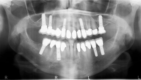
FIG. 32-14 A panoramic radiograph used for postoperative assessment of multiple successfully restored rootform implants. The threads are visualized on all of the implants except for the mandibular right premolar, which is a smooth cylinder.
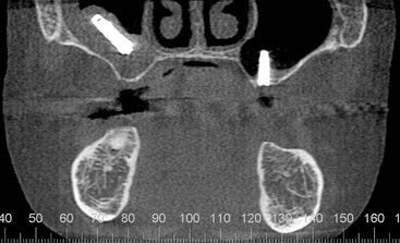
FIG. 32-15 Reformatted cone-beam CT study for postoperative assessment of an implant cylinder displaced into the right maxillary sinus, associated with mucositis in the right antrum. The implant on the left alveolus is not well supported by bone and extends well into the antrum. (Courtesy Oral and Maxillofacial Imaging Center, Baylor College of Dentistry, Dallas, Tex.)
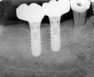
FIG. 32-16 A periapical radiograph of two successful dental implants. Note the close apposition of the bone to the surface of each implant. A minor amount of saucerization is present at the alveolar crest adjacent to the distal fixture.
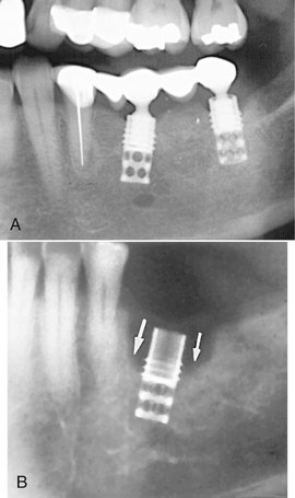
FIG. 32-17 A, Marginal bone loss around the cervical region of a rootform dental implant (portion of a panoramic radiograph). B, Periapical radiograph of moderate bone loss (“saucerization” type) around the cervical region of a rootform dental implant (arrows).
The success of an implant can also be evaluated by the appearance of normal bone surrounding it and its apposition to the surface of the implant body. The development of a thin radiolucent area that closely follows the outline of the implant usually correlates to clinically detectable implant mobility; it is an important indicator of failed osseointegration (Fig. 32-18). Changes in the periodontal ligament space of associated teeth (natural abutment) are also useful in monitoring the functional competence of the implant-prostheses composite. Any widening of the periodontal ligament space compared with baseline radiographs indicates poor stress distribution and forecasts implant failure (Table 32-3). After successful implantation, radiographs may be made at regular intervals to assess the success or failure of the implant fixture. Advanced imaging studies may be necessary for adequate assessment in some cases (Figs. 32-19 and 32-20).
TABLE 32-3
Radiographic Signs Associated with Failing Endosseous Implants
| RADIOGRAPHIC APPEARANCE | CLIINICAL IMPLICATIONS |
| Thin radiolucent area that closely follows the entire outline of the implant | Failure of the implant to integrate with the adjoining bone |
| Crestal bone loss around the coronal portion of the implant | Osteitis resulting from poor plaque control, adverse loading, or both |
| Apical migration of alveolar bone on one side of the implant | Nonaxial loading resulting from improper angulation of the implant |
| Widening of the periodontal ligament space of the nearest natural (tooth) abutment | Poor stress distribution resulting from biomechanically inadequate prosthesis-implant system |
| Fracture of the implant fixture | Unfavorable stress distribution during function |
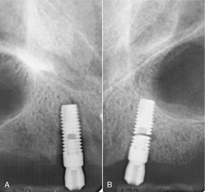
FIG. 32-18 A, Periapical radiograph of bone loss around a root-form dental implant (thin radiolucent band surrounding the implant), indicating failure of osseous integration. B, Periapical view of a fractured endosseous implant.
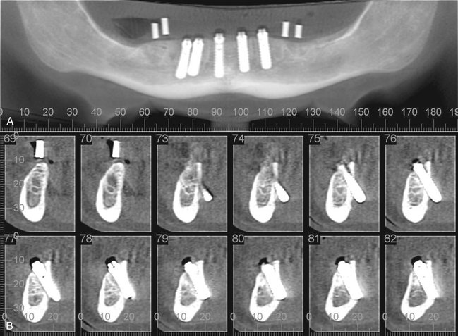
FIG. 32-19 A, Panoramic-like curved linear reformatted cone-beam CT (CBCT) image initially made for implant planning. In this image, the existing implants appear reasonably normal in orientation. B, The cross-sectional reformatted CBCT images reveal nonrestorable ectopic placement of the existing implants with lingual cortical perforation and extension into the lingual tissues. (Courtesy Oral and Maxillofacial Imaging Center, Baylor College of Dentistry, Dallas, Tex.)
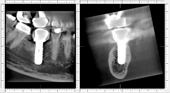
FIG. 32-20 Reformatted cone-beam CT images of a symptomatic patient reveal embarrassment and compression of the mandibular canal by the implant.
In summary, diagnostic imaging is an integral part of dental implant therapy for presurgical planning, intraoperative assessment, and postoperative assessment by use of a variety of imaging techniques. Cross-sectional imaging is increasingly considered essential for optimal implant placement, especially in the case of complex reconstructions.
Avendanio, B, Frederiksen, NL, Benson, BW, et al. Estimate of radiation detriment: scanography and intraoral radiology. Oral Surg Oral Med Oral Pathol Oral Radiol Endod. 1996;82:713–719.
Cohnen, M, Kemper, J, Möbes, O, et al. Radiation dose in dental radiology. Eur Radiol. 2002;12:634–637.
Frederiksen, NL, Benson, BW, Sokolowski, TW. Risk assessment from film tomography used for dental implant diagnostics. Dentomaxillofac Radiol. 1994;23:123–127.
Frederiksen, NL, Benson, BW, Sokolowski, TW. Effective dose and risk assessment from computed tomography of the maxillofacial complex. Dentomaxillofac Radiol. 1995;24:55–58.
Lecomber, AR, Yoneyama, Y, Lovelock, DJ, et al. Comparison of patient dose from imaging protocols for dental implant planning suing conventional radiography and computed tomography. Dentomaxillofac Radiol. 2001;30:255–259.
Ludlow, JB, Davies-Ludlow, LE, Brooks, SL, et al. Dosimetry of 3 CBCT devices for oral and maxillofacial radiology: CB Mercuray, NewTom 3G and i-CAT. Dentomaxillofac Radiol. 2006;35:219–226.
Scaf, G, Lurie, AG, Mosier, KM, et al. Dosimetry and cost of imaging for osseointegrated implants with film-based and computed tomography. Oral Surg Oral Med Oral Pathol Oral Radiol Endod. 1997;83:41–48.
Schulze, D, Heiland, M, Thurmann, H, et al. Radiation exposure during midfacial imaging using 4- and 16-slice computed tomography, cone beam computed tomography systems and conventional tomography. Dentomaxillofac Radiol. 2004;33:83–86.
COMPUTED TOMOGRAPHY (CBCT AND MDCT)
Hashimoto, K, Kawashima, S, Araki, M, et al. Comparison of image performance between cone-beam computed tomography for dental use and four-row multidetector helical CT. J Oral Sci. 2006;48:27–34.
Hatcher, DC, Dial, C, Mayorga, C. Cone beam CT for presurgical assessment of implant sites. J Calif Dent Assoc. 2003;31:825–833.
Lascala, CA, Panella, J, Marques, MM. Analysis of the accuracy of linear measurements obtained by cone beam computed tomography (CBCT–NewTom). Dentomaxillofac Radiol. 2004;33:291–294.
McGivney, GP, Haughton, V, Strandt, JA, et al. A comparison of computer-assisted tomography and data-gathering modalities in prosthodontics. Int J Oral Maxillofac Implants. 1986;1:55–68.
Rothman, SLG. Dental applications of computed tomography—surgical planning for implant placement. Chicago: Quintessence; 1998.
Scarfe, WC, Farman, AG, Sukovic, P. Clinical applications of cone-beam computed tomography in dental practice. J Can Dent Assoc. 2006;72:75–80.
Schwarz, MS, Rothman, SL, Rhodes, ML, et al. Computed tomography, I: preoperative assessment of the mandible for endosseous implant surgery. Int J Oral Maxillofac Implants. 1987;2:137–141.
Schwarz, MS, Rothman, SL, Rhodes, ML, et al. Computed tomography, II: preoperative assessment of the maxilla for endosseous implant surgery. Int J Oral Maxillofac Implants. 1987;2:143–148.
Sukovic, P. Cone beam computed tomography in craniofacial imaging. Orthod Craniofacial Res. 2003;6(1 Suppl):31–36.
Wishan, MS, Bahat, O, Krane, M. Computed tomography as an adjunct in dental implant surgery. Int J Periodontics Restorative Dent. 1988;8:30–47.
Zhang, L, Zhu, XR, Lee, AK, et al. Reducing metal artifacts in cone-beam CT images by preprocessing projection data. Int J Radiat Oncol Biol Phys. 2007;67:924–932.
Ekestubbe, A, Gröndahl, K, Gröndahl, HG. The use of tomography for dental implant planning. Dentomaxillofac Radiol. 1997;26:206–213.
Gröndahl, K, Ekestubbe, A, Gröndahl, HG, et al. Reliability of hypocycloidal tomography for the evaluation of the distance from the alveolar crest to the mandibular canal. Dentomaxillofac Radiol. 1991;20:200–204.
Stella, JP, Tharanon, W. A precise radiographic method to determine the location of the inferior alveolar canal in the posterior edentulous mandible: implications for dental implants, I: technique. Int J Oral Maxillofac Implants. 1990;5:15–22.
Stella, JP, Tharanon, W. A precise radiographic method to determine the location of the inferior alveolar canal in the posterior edentulous mandible: implications for dental implants, II: clinical application. Int J Oral Maxillofac Implants. 1990;5:23–29.
Benson, BW. Diagnostic imaging for dental implant assessment. Tex Dent J. 1995;112:37–41.
Benson, BW. Presurgical radiographic planning for dental implants. Oral Maxillofac Surg Clin North Am. 2001;13:751–761.
DeSmet, E, Jacobs, R, Gijbels, F, et al. The accuracy and reliability of radiographic methods for the assessment of marginal bone level around oral implants. Dentomaxillofac Radiol. 2002;31:176–181.
Holmes, SM. iCAT scanning in the dental office. Fortress Guardian. 2007;9:2.
Milgrom, P, Getz, T. Implants: growing concern. Dental Claims and Insurance News. 1994;8:1. [newsletter]
Reddy, MS, Wang, IC. Radiographic determinants of implant performance. Adv Dent Res. 1999;13:136–145.
Sahiwal, IG, Woody, RD, Benson, BW, et al. Radiographic identification of nonthreaded endosseous dental implants. J Prosthet Dent. 2002;87:552–562.
Sahiwal, IG, Woody, RD, Benson, BW, et al. Radiographic identification of threaded endosseous dental implants. J Prosthet Dent. 2002;87:563–577.
Tyndall, DA, Brooks, SL. Selection criteria for dental implant site imaging: a position paper of the American Academy of Oral and Maxillofacial Radiology. Oral Surg Oral Med Oral Pathol Oral Radiol Endod. 2000;89:630–637.
Misch, CE. Dental implant prosthodontics. St. Louis: Elsevier Mosby; 2005.
Miyamoto, I, Tsuboi, Y, Suwa, H, et al. Influence of cortical bone thickness and implant length on implant stability at the time of surgery—clinical, prospective, biomechianical, and imaging study. Bone. 2005;37:776–780.
Palmer, RM, Smith, BJ, Howe, LC, et al. Implants in clinical dentistry. Chicago: Quintessence; 1998.
Sahiwal, I, Woody, RD, Benson, BW, et al. Macro design morphology of endosseous dental implants. J Prosthet Dent. 2002;87:543–551.
Cehreli, MC, Aslan, Y, Sahin, S. Bilaminar dual-purpose stent for placement of dental implants. J Prosthet Dent. 2000;84:55–58.
Kopp, KC, Koslow, AH, Abdo, OS. Predictable implant placement with a diagnostic/surgical template and advanced radiographic imaging. J Prosthet Dent. 2003;89:611–615.
Ku, YC, Shen, YF. Fabrication of a radiographic and surgical stent for implants with a vacuum former. J Prosthet Dent. 2000;83:252–253.
Fortin, T, Bosson, JL, Coudert, JL, et al. Reliability of preoperative planning of an image-guiding system for oral implant placement based on 3-dimensional images: an in vivo study. Int J Oral Maxillofac Implants. 2003;18:886–893.
Guerrero, ME, Jacobs, R, Loubele, M, et al. State-of-the-art cone beam CT imaging for preoperative planning of implant placement. Clin Oral Investig. 2006;10:1.
Rosenfeld, AL, Mandelaris, GA, Tardieu, PB. Prosthetically directed implant placement using computer software to ensure precise placement and predictable prosthetic outcomes, 1: diagnostics, imaging, and collaborative accountability. Int J Periodontics Restorative Dent. 2006;26:215–221.