24 Complications and management
Introduction
Scientific literature has evidenced that implant therapy obtains a success rate greater than 90%. With the increasing acceptance of dental implantation as a viable tooth replacement therapy, complications and failure rates have also increased proportionately. Complications and failures in implant dentistry can range from minor to major, reversible to irreversible, and problematic to detrimental. As a result, these clinical problems cause frustrations and disappointments for patients and dental professionals and cast doubts on the success of dental implant therapy. These problems can have many different levels of undesirable consequences that may lead to compromised or less than optimal clinical results for the patients, nonproductive wasted clinical chair time, extra financial burden to the patient and dentist, create antagonistic tension in patients, and ultimately affect the reputation of the dentist and the profession. Complaints to regulatory colleges and litigations involving implant dentistry have also increased over the past decade. Understanding the various complications and failures in implant dentistry can lead to prevention, early detection, and better management of implant cases. A range of possible surgical and prosthetic problems, their prevention, and management are described below.
Complications
Nerve injury
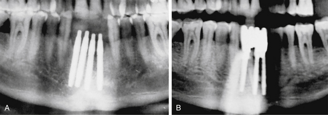
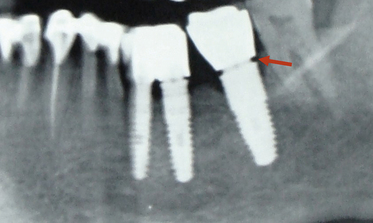
Many implant surgeons decide the final implant length only by referring to the dental or panoramic radiograph. These radiographs usually show some degree of magnification, which may result in nerve injury during implant placement if the longest implant is placed with reference to the radiograph without considering the magnification factor. Moreover, the radiographs often do not show the clear path of the mandibular canal, which can also be a cause of misdiagnosis and nerve injury. The mandibular canal is the most important vital structure that should be taken care of during implant insertion in the mandibular posterior region. The path of the canal should be clearly evaluated to assess the bone height available to insert the implant. The presence of the anterior loop should also be evaluated when inserting the implant in the mandibular premolars and canine region. For cases with limited bone height above the mandibular canal, dental CT scan should be used to plan for the implant with appropriate dimensions. However, the implant should be placed minimum 2–3 mm short of the mandibular canal (Fig 24.1A–D).
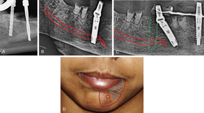
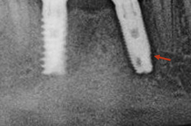
Fig 24.1 (A) Radiograph showing the pilot drill encroaching at the nerve. Further drilling reaching the same depth must be avoided and an implant with shorter length should be inserted. (B and C) If the post implantation radiograph shows that the implant has been placed through the mandibular canal, the implant should immediately be removed and another short length implant inserted or the same implant inserted with different angulation if possible, to avoid nerve injury. (D) If the patient complains of neurosensory dysfunction on the second day of surgery, the areas of anaesthesia, paraesthesia, and dysaesthesia should be marked differently on the patient’s lower jaw and photographed for future comparisons of recovery.
Prevention and management
1. Detailed radiographic and CT planning to evaluate the exact path of the mandibular canal.
2. Length of the planned implant should be 2-3 mm less than the height of the bone present above mandibular canal (3.0 mm safety distance) (Fig 24.2).
3. If the case has been planned using only the panoramic radiograph, the 25% magnification of the radiograph should be reduced from the bone height measured above the canal in the radiograph. For example, if the panoramic radiograph shows 15 mm bone height above the canal, the actual bone height can be only 12 mm and after deducting another 3 mm as the safety distance, only a 9 mm long implant should be chosen for placement. However, if the dental CT scan, which shows the actual bone dimensions, shows 15 mm bone height above the mandibular canal, the surgeon can place a 12 mm long implant.
4. In the case of limited bone height above the mandibular canal, a radiograph should be taken after pilot drilling short of 3 mm from the planned implant depth, to reconfirm the canal position in respect to the implant length (Fig 24.3).
5. If the osteotomy has been prepared and the implant has been placed with its apex just touching the canal, the patient should be recalled two days after surgery and enquired if there is any altered sensation over the chin and lower lip of the same side. If the answer is “Yes”, then either the implant should be unscrewed 1.0 mm to release the pressure from the nerve or it can be removed and replaced with a shorter length implant. The patient may, however, take 2–4 months to recover from the paraesthesia.
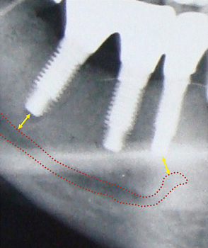
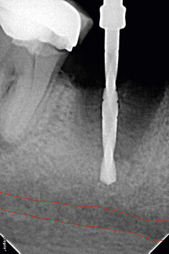
Fig 24.3 The dental radiograph with pilot drill into the osteotomy is taken to assess the distance from mandibular canal.
If the implant surgeon has severely injured or crushed the nerve, it may require microsurgical repair of the nerve, if the paraesthesia is not recovered by therapeutic measures. The nerve injury may produce short-term or even protracted paraesthesia (abnormal sensation without being unpleasant or painful) or dysaesthesia (unpleasant or painful sensation) to the patient over the lip and chin of the side.
Treatment to recover the altered nerve functions
1. Drug therapy. The following drugs should be prescribed to the patient:
2. Physical therapy. Warm compressions and massage of the paralysed area facilitate nerve restoration and relieves neural pain.
3. Microsurgical repair. If the altered nerve sensations have not even started recovering in 2–3 months, the patient should be referred to a surgeon who has expertise in performing microsurgical repair of the neural tissues. To microsurgically repair the crushed nerve, the mesial and distal ends of the nerve bundles are located, the crushed part of the nerve is resected, two to three nonresorbable sutures are placed to approximate the ends, and a collagen membrane is wrapped around the repaired nerve for predictable nerve tissue regeneration.
Dr WL Gore and Dr Flagstaff used a polytetrafluoroethylene (PTFE) tube to repair the inferior alveolar and lingual nerve. Proximal and distal ends were placed in the PTFE tube and secured using 8-0 nylon sutures. The procedure was performed in a total of seven patients and only two patients recovered from the paraesthesia.
Maxillary sinus perforation
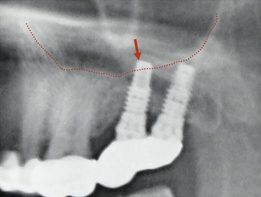
The implant surgeon may inadvertently perforate the sinus floor during implant placement in the maxillary posterior region. If there is only a small perforation with the pilot drill, osteotomy preparation can be continued 2 mm short of the sinus floor and the implant can be placed. Small perforations spontaneously heal and do not cause any problem to implant healing. If a large perforation has been made into the sinus membrane, the surgeon can abort the implant placement and close the flap, and re-enter after it is healed in 3–4 months. Alternatively, the sinus membrane can be elevated with the lateral approach, the perforation can be repaired using resorbable collagen membrane and the implant can be placed in the same sitting. According to the traditional concept, if the implant perforates the sinus membrane and penetrates the sinus, it can be a source of periodic sinusitis. Recent studies have shown that if the implant apex has penetrated into the sinus 2 mm or less, the membrane regenerates and covers it within few weeks; and even if it has penetrated more than 2 mm, being a sterile material it does not usually cause any problem. However, further clinical trials and scientific evidence are required to prove that implant apex penetration in the sinus is safe and does not cause any long-term complication to the sinus cavity or impede implant survival (Fig 24.4).
Dehiscence/perforation through the lingual cortical plate
Perforation through the palatal cortical plate in the maxilla is very rare because of its high density and favourable topography. When the perforation occurs through the lingual cortical plate of the mandible, it is often difficult to elevate the lingual flap to such an extent as to expose the perforation (especially if it has occurred deep apically), and to graft the perforation. The appropriate way is to abort the implant placement and leave the site to heal, with or without grafting the already prepared osteotomy. Implant placement can be attempted again once the site has healed. Though very rare, a life-threatening haemorrhage may happen with the perforation of the lingual cortical plate when drilling for mandibular implants. The drill may traumatize two major arteries: (i) the lingual artery (which supplies the tongue) and its terminal branches called sublingual arteries supplying the lingual and gingival aspects of the anterior cortical plate of the mandible and (ii) the facial artery, which runs under the base of the mandible in the second molar region. Significant internal bleeding from these arteries in the floor of mouth may result in a life-threatening haemorrhage, which causes swelling of the floor of mouth and tongue, and respiratory obstruction. When such a haemorrhage is noticed, the tongue should be pulled out and pressure placed along the inner and inferior aspects of the body of the mandible. One should also compress the site with one finger intraorally over the site and another finger placed extraorally, compressing the two fingers together. A haemostatic agent should be placed into the osteotomy and the patient should immediately be transported to the hospital where a team of surgeons can ligate the injured vessels, give an endotracheal intubation, or perform an emergency tracheotomy (Fig 24.5A and B).
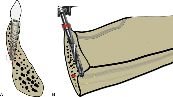
Fig 24.5 The anterior mandible is the area where the bony ridge maximally changes its axial direction through the different stages of bone resorption. (A) One should carefully evaluate the bony ridge topography to avoid any dehiscence through the lingual cortical plate during osteotomy preparation. (B) Care must also be taken to avoid the penetration through the submandibular fossa which is located below the mylohyoid line and also into the sublingual space in the anterior mandible where the sublingual artery is located. Inadvertent penetration of these lingual plates can be avoided by appropriately directing the pilot drill towards the buccal and monitoring the area with digital contact on lingual aspect while drilling.
The risk of lingual plate perforation or fenestration, due to lingual concavity, in an edentulous posterior mandible in the region of second premolar or first molar was found to be only 0.053% if a regular 3.75 mm diameter tapered implant was used. In the presence of significant lingual concavity in the posterior mandible, a smaller regular diameter implant with a stepped taper design should be considered, to avoid potential fatal damage of the vital structures.
Dehiscence/perforation through the facial cortical plate
Any dehiscence or perforation through the facial cortical plate during osteotomy preparation can be grafted using autogenous bone and/or bone substitutes, after implant placement in the same sitting (Fig 24.6A–D).
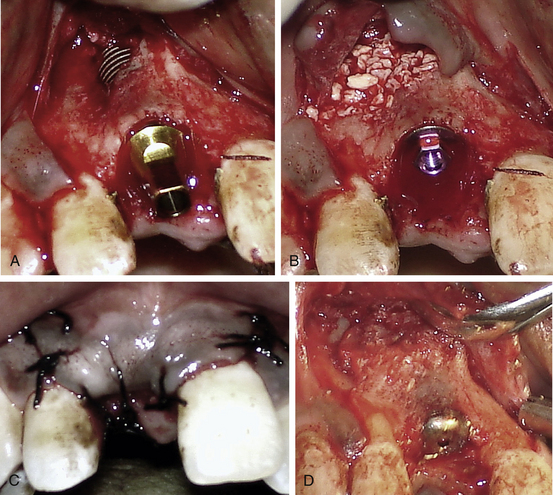
Fig 24.6 (A) A fenestration through the labial cortical plate can be seen with the implant thread exposure. (B and C) The site is grafted using Bio-Oss (xenograft) graft material and the flap is sutured back without using any barrier membrane. (D) The implant is uncovered after 4 months showing new bone formation at the grafted site.
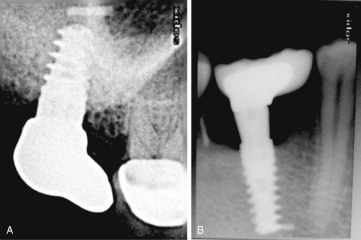
Drilling through the root of the adjacent tooth
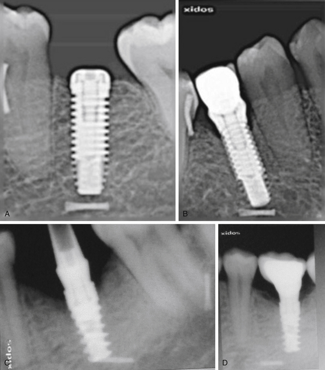
Drilling in the wrong direction or the presence of inclined roots of the adjacent tooth may inadvertently cause this complication (Fig 24.7A–C).
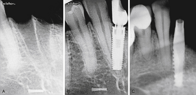
Fig 24.7 (A and B) Implant placed at the site of the madibular lateral incisor has penetrated through the canine root. (C) Implant encroaching the periodontal ligaments of the adjacent tooth.
Prevention
Meticulous treatment planning using radiographs and CT images and careful osteotomy preparation in three-dimensionally correct directions, which can be evaluated with the radiograph after the drilling to partial depth, can avoid this complication.
Management
The management of this complication depends on the severity of injury to the adjacent tooth that occurs during implant placement.
1. Encroachment only at the root apex. If the pilot drill has only encroached at the root apex, further osteotomy should be prepared in the correct direction and the implant should be placed. If the tooth becomes symptomatic, root canal therapy should be done in a follow-up visit.
If the implant has been placed encroaching the root apex, root canal therapy should be done in the same sitting using only sterile saline for root canal irrigation. The root canals should be obturated at the same sitting.
2. Perforation through the apical third. Osteotomy should be prepared in the correct direction and the implant placed. Root canal therapy with simultaneous resection of the perforated root apex should be done with the lateral approach and the area should be grafted in the same surgical sitting using any bone substitute.
3. Perforation through the middle third. The osteotomy should be prepared in the correct direction and the implant should be inserted. The tooth should be extracted and socket grafted in the same surgical sitting, using any bone substitute.
Off-axis implant placement
Off-axis implant placement not only results in a challenging situation for prosthetic rehabilitation but also causes the resorption of thin bone at the crestal region, which leads to bone defects and soft tissue recession (Figs 24.8 and 24.9).
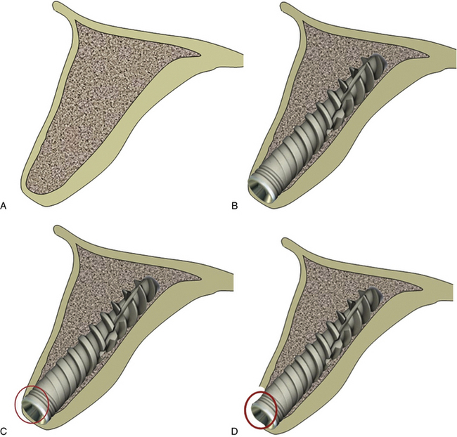
Fig 24.8 (A) The cross-section of anterior maxilla before implant insertion (B) implant placement in the incorrect direction, (C) causing thin labial cortical plate at the crestal region, (D) which fails to survive and gets resorbed.
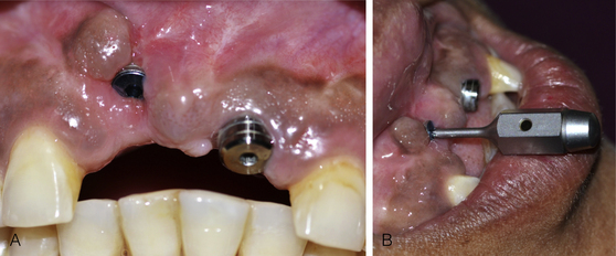
Fig 24.9 (A) The implant placed in the wrong axis resulted in loss of thin hard and soft tissue on the labial aspect if restored, (B) it will lead to a very unaesthetic prosthesis.
Management
The implant should be removed and the same or a new implant should be reinserted at the correct axis. (Figs 24.10–24.14).
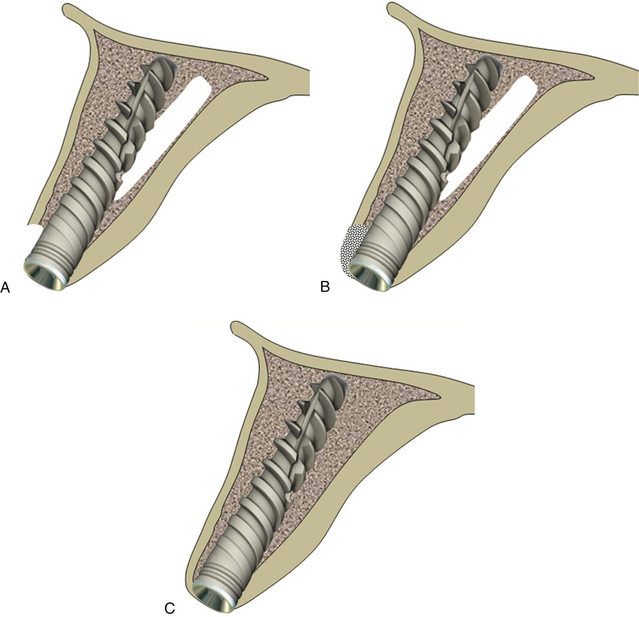
Fig 24.10 The implant can be removed and osteotomy prepared in the correct direction. (A) The same or a new implant is inserted. (B and C) The bone defect is grafted using autogenous or synthetic graft material and the flap is sutured back for submerged healing for a minimum of 4 months, which allows new bone formation at the area of the defect and implant to get osseointegrated.
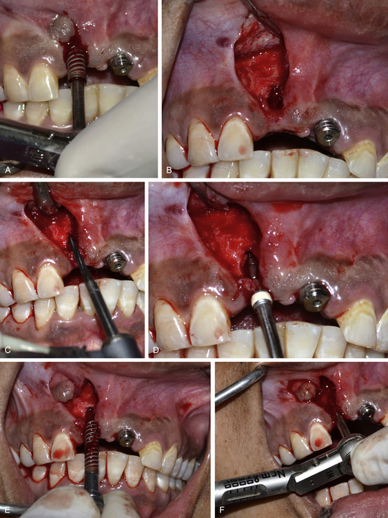
Fig 24.11 (A) The osseointegrated implant is removed using the ratchet. A papilla preservation flap is elevated to expose the implant site. (B) A bone defect is visible, which developed after the loss of thin labial cortical plate at the crestal region because of incorrect implant angulation. (C) A side-cutting Lindemann drill is used to drill the hard and thick palatal cortical plate and (D) the osteotomy is prepared in the correct direction using implant drills. (E) The same implant is reinserted with the correct angulation. (F) An adequate primary stability of the implant is achieved.
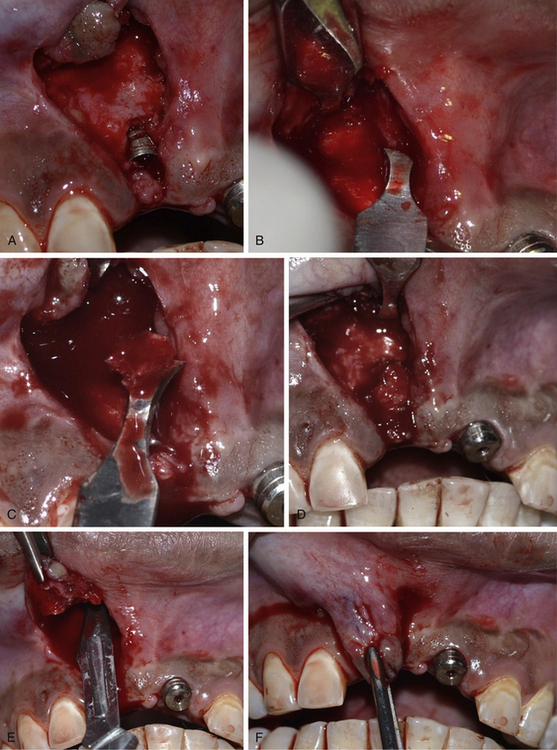
Fig 24.12 (A) The labial bone defect can be seen around the implant neck area; changing the implant direction has provided adequate room to graft the defect. (B–D) Autogenous bone is harvested from the subnasal region using a sharp chisel and used to graft the defect. (E and F) Releasing incisions are made through the periosteum of the flap to coronally advance it to achieve primary closure.
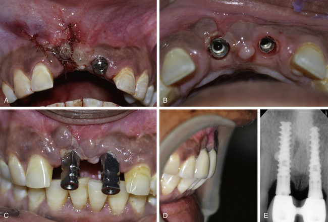
Fig 24.13 (A) The flap is sutured back with the primary closure and the site is allowed to heal for 4 months. (B and C) The implant uncovered using tissue punch shows the correct axis of the implant. (D) The implants are restored with an aesthetically acceptable prosthesis. (E) Postloading radiograph. Though, these implants are in function since 2 years with stable crestal bone level but removal and immediate reinsertion of the same implant in the same patient need further clinical trials.
Inappropriate three-dimensional implant positioning in the aesthetic region
The implant positioning should be three-dimensionally accurate in the aesthetic region to achieve optimal hard and soft tissue aesthetics. When adjacent teeth are present with the gingival collar at the correct position, the implant should be placed in such a way that its platform is finally positioned 2–3 mm apical to the imaginary line connecting the cementoenamel junction (CEJ) of two adjacent teeth, to achieve the adequate emergence profile through the soft tissue. If soft tissue recession has already occurred on the adjacent teeth, the implant platform should be positioned 2–3 mm apical to the gingival zenith. The implant platform should also be placed 1–1.5 mm palatal to the imaginary line connecting the CEJ of two adjacent teeth (Fig 24.15A–D).
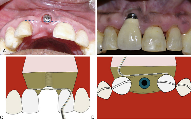
Fig 24.15 (A and B) Implant has been placed far facial and apical to the ideal position in the aesthetic region. (C) To achieve adequate aesthetic outcome, the implant should be positioned 2–3 mm apical to the imaginary line connecting the CEJ of two adjacent teeth or 2–3 mm apical to the gingival zenith. (D) The implant platform should also be placed 1–1.5 mm palatal to the imaginary line connecting the CEJ of two adjacent teeth.
Implants too close to each other
If two adjacent implants are placed very close to each other, the thin bone (less than 3 mm) present between two adjacent implants fails to survive because of lack of nutrient supply and gets resorbed (Fig 24.16A and B).
Incomplete seating of the prosthesis
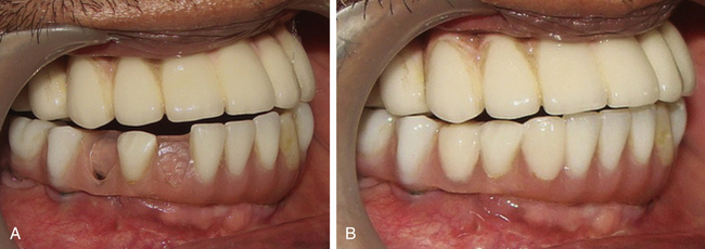
Incomplete seating of the prosthesis on the abutment creates a subgingival gap, which may retain plaque and lead to chronic inflammation of the peri-implant tissues. This may also lead to instability of the marginal gingival tissues and in cases with the thin soft tissue biotype, may lead to recession or small fenestrations within the peri-implant tissues (Fig 24.17).
Causes of improper seating of the prosthesis onto an abutment
1. Resistance from peri-implant tissues or entrapment of soft tissue between the abutment–crown margins during prosthesis seating.
2. Premature interproximal contacts on the adjacent teeth.
3. Incorrect orientation and seating of the abutment on the implant.
4. Inaccurate impression recording, transfer, and prosthesis fabrication.
Prevention and management
1. Accurate impression recording, transfer, and prosthesis fabrication.
2. The abutment should be transferred to the implant with the same orientation as on the working cast.
3. Crown seating should be checked visually and confirmed with a radiograph, prior to final cementation.
4. When the surrounding soft tissue is preventing complete seating of an implant crown, it should be carefully trimmed to completely seat the prosthesis onto the abutment.
Luting cement retention into the peri-implant soft tissue
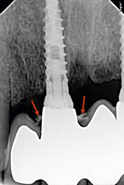
Implant abutment–crown margins which are typically subgingival, pose a significant challenge when excess cement is removed following crown cementation to the implant abutment. This may be further compounded by the fact that the peri-implant tissues are tightly adapted to the newly placed implant crown, making it difficult to negotiate the subgingival area. Radiographic evaluation should always be accompanied with careful clinical evaluation of the peri-implant tissues to see if any excessive cement is present in the soft tissue. The retention of the cement in the peri-implant soft tissue may lead to recurrent pain, swelling, soft tissue inflammation, and crestal bone resorption (Fig 24.18).
Prevention
1. Avoid placing the implant abutment–crown margin interface deeper than 2–3 mm subgingivally, by selecting a final abutment with appropriate collar height; if it is any deeper, removal of excess cement becomes very difficult without surgical access.
2. excessive amount of cement should not be used as excess cement gets expelled comparatively deeper subgingivally, if compared to the conventional margins associated with routinely fixed crowns placed on prepared natural teeth. This is because, the implant does not have any connective tissue attachment which can prevent the cement expulsion deep into the peri-implant soft tissue.
3. Use radiopaque luting cements that can be visualized in the radiograph.
4. Using dual-cure resin cements which set quickly; the excess part can be easily removed from the deep subgingival area using a fine probe.
Management
The presence of residual cement often results in bleeding on probing, oedematous soft tissue, pain, exudate from the gingival sulcus, slight discomfort, etc. within 3–4 months of completion of the prosthesis. Occasionally the area remains asymptomatic even for years following the completion of the prosthesis. The acute inflammation associated with the presence of excess subgingival cement may also lead to crestal bone loss. Thus, the impacted cement should be identified in time and removed so as not to jeopardize the long-term health of the implant. If excess cement is removed within 3–4 months post restoration, it is possible to see reversal of crestal changes radiographically. Removal of excess subgingival cement involves anaesthetizing the peri-implant tissues with local anaesthetic and then using a periodontal curette to carefully negotiate the sulcus until the tip of the instrument makes contact with the cement. The implant surgeon should aim to get the tip of the instrument below the deposit so that a coronal sweeping action will dislodge the cement and remove it from the sulcus. In most cases, the tissues around the implant get softened and more pliable due to the associated inflammation, and while this assists with instrumentation of the subgingival areas, care needs to be taken to minimize trauma to the peri-implant tissues. This is particularly important in patients with a thin biotype and with implants in the aesthetic zone, where tissue trauma may lead to unsightly recession of the marginal peri-implant tissues. Furthermore, care should be taken to minimize scratching of the implant abutment surface during removal of the subgingival cement. When possible, plastic implant scalers should be used; however, these will often be insufficient to remove adherent excess cement. Fine-tipped periodontal curettes, such as a Mini-Five or similar curettes, used judiciously are often a better alternative.
Suture line opening
The open suture line should not be re-sutured but the patient should be instructed to keep it clean, as it heals by secondary intention in 2–3 weeks (Fig 24.19).
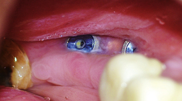
Fig 24.19 Suture line opening may result in cover screw exposure to the oral environment; the surgeon should not attempt to re-suture the flap but allow it to heal by the process of secondary intention. The patient should be instructed to keep the area very clean with the mouth rinses, soft brushes, etc. so that the tissue grows from the flap margins and covers the implant. If the implant is deep-seated, the deep soft tissue may collect food particles, which are quite difficult to clean and may cause infection to the implant. In such cases the cover screw should be replaced with a long gingival former. The implant surgeon can also irrigate the site twice a day with an antibiotic solution (e.g. injectable form of clindamycin) which raises the concentration of the antibiotic at the local site and prevents chances of infection to the implant till the soft tissue gets healed.
Implant thread exposure
Exposure of implant threads in the oral environment may cause the collection of plaque over the exposed rough surface of the implant, which may further cause peri-implantitis and loss of peri-implant hard and soft tissue.
Causes of implant thread exposure
1. Suture line opening and loss of graft in cases where simultaneous bone grafting has been performed with implant placement (Fig 24.20A).
2. Soft tissue recession following crestal bone resorption.
3. More superficial implant placement.
4. Thin mobile soft tissue recedes with muscle pull (Fig 24.20B).
Management
If soft tissue healing has not covered the exposed implant threads, the threads should either be covered using soft tissue grafting with or without simultaneous bone grafting, or adequate grinding and polishing should be done to make the surface very smooth, to prevent any plaque collection or peri-implantitis.
Post implantation infection
If the infection is limited to the soft tissue, a small gum boil will be noticed over the implant site. It can be punctured using a sharp probe and irrigated with chlorhexidine solution or citric acid. It heals and the pain subsides within 24 h. If there is continuous purulent discharge and severe pain which is not relieved by oral analgesics, the infection has reached to the bone–implant body interface. In such cases, the implant surgeon should immediately remove the implant and prescribe some good antibiotic like tab Augmentin 1000 mg twice a day for 5–7 days. A new implant can be inserted when the site gets healed in 6 weeks (Fig 24.21A–F).
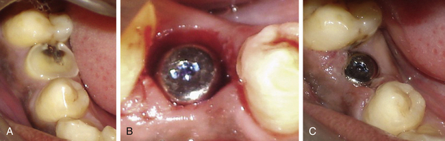
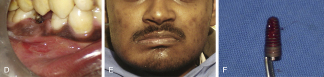
Fig 24.21 (A and B) The infected tooth is extracted and replaced by immediate implant. All measures were taken to prevent postoperative infection, such as prophylactic oral antibiotics, curetting out all the granulation tissue from the socket and irrigation of the socket with antibiotic solution before implant placement. (C) Normal soft tissue healing was seen at the second day after surgery (D) but the patient came again after 3 days with severe throbbing pain and swelling in the implant region. (E) Extraoral swelling could also be noticed. All attempts, such as injectable antibiotics and analgesics failed to reduce the pain and swelling because once the implant has received infection, it starts acting as a nonresorbable foreign body structure. (F) After the implant was removed the pain and swelling subsided within 24 h and the site healed under regular oral antibiotics.
Implant failure
1. Post implant insertion. If the implant fails within a few days after insertion, the causes may be infection, pressure necrosis, premature loading over inadequately stabilized implant etc.
2. During implant uncovery. If the implant fails to osseointegrate, a fibrous tissue grows between implant surface and surrounding bone, which often granulates and gets infected. It may sequestrate through the overlying soft tissue and often remains asymptomatic (Figs 24.22 and 24.23).
3. After prosthetic loading. If the implant fails after it is loaded in function, the causes may be either poor osseointegration, as in case of extremely low-density bone, or because the implant has been restored with the prosthesis with extremely offset occlusal loading.
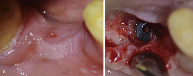
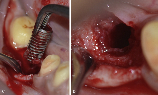
Fig 24.22 (A) A soft tissue boil at the implant site was seen during implant uncovery with a little discharge but no symptoms of pain or swelling. (B) A large amount of granulation tissue can be seen surrounding the implant indicating fibrous integration and failure of implant. (C) The implant should be removed and (D) all the granulation tissue should be curretted out. The flap is sutured back. A new implant can be inserted after the site heals in 6–8 weeks.
Pressure necrosis
If the implant has been inserted into the high-density D1 or D2 type bone and screwed at a very high torque, it may lead to pressure necrosis of the surrounding bone and the patient will complain of continuous pain not relieved by analgesics, for weeks after the surgery.
Prevention
1. Use of new drills when drilling into high-density bone.
2. Drilling at higher speed and with maximum amount of chilled saline irrigation flow to cool down the bone.
3. Use of final drill with the diameter only 0.2 mm less than the implant diameter (e.g. 3.65 mm final drill for a 3.75 mm diameter implant).
4. Using the bone tap to prepare threads in the bone to accommodate implant threads.
5. Application of ice packs on the facial skin over the implant site and mouth rinsing with cold water for 48 h after implant placement.
6. Injectable/oral steroids (Dexona inj. just after surgery and tab. Decadron 4 mg once a day for the next 3 days) to reduce postoperative inflammation.
Treatment
If pain with the same intensity persists even after 1 week, the implant should be removed and another new implant inserted after 6 weeks (Fig 24.24A–C).
Osseointegrated implant removal on unscrewing cover screw/gingival former
If the cover screw or gingival former has been screwed to the implant using a high torque, it often becomes difficult to remove it at the implant uncovery or prosthetic phase. If it is removed at high torque, the implant itself may come out with the cover screw/gingival former, especially if the implant has been placed in poor-density bone (Fig 24.25).
Crestal bone resorption
Crestal bone resorption is one of the most common problems in dental implantology.
Causes
1. Occlusal forces on the implant prosthesis are off-axis to the implant.
2. Implant with a wider platform is placed into the narrow crestal bone (Fig 24.26A).
3. Plaque collection – peri-implantitis.
4. Compromised (thin, unstable, and not keratinized) peri-implant soft tissue.
Prevention
1. Placement of two implants for the large mesiodistal space of a missing molar.
2. Implant placement along the axis of the future prosthesis (prosthetically guided implant placement).
3. Use of implant with platform switching feature (Figure 24.26B).
4. Fabrication of the implant prosthesis with narrow occlusal table (buccolingual).
5. Oral hygiene maintenance to prevent plaque collection and peri-implantitis.
6. Soft tissue grafting for compromised soft tissue around the implant prosthesis.
Connection screw loosening
Connection screw loosening is commonly encountered in implant practise.
Prevention
1. Minimize offset forces over the prosthesis.
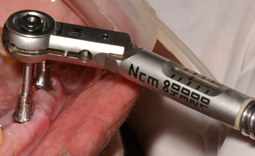
2. Final screw tightening at 30–35 Ncm using the torque ratchet (Fig 24.27).
Management
1. If the connection screw of the screw-retained prosthesis gets loose, the filling material is removed from the screw hole in the prosthesis and the connection screw is tightened again at 30–35 Ncm using a torque ratchet.
2. If the connection screw of cement-retained prosthesis gets loose, the prosthesis is removed, or the screw is re-tightened and the same prosthesis or a new prosthesis is fixed on top of the abutment. Alternatively, the connection screw Location and direction are identified with radiographs and a small hole is prepared through the prosthesis to access the connection screw. The screw is re tightened using a torque ratchet and the access hole is closed using gutta-percha and composite (Fig 24.28).
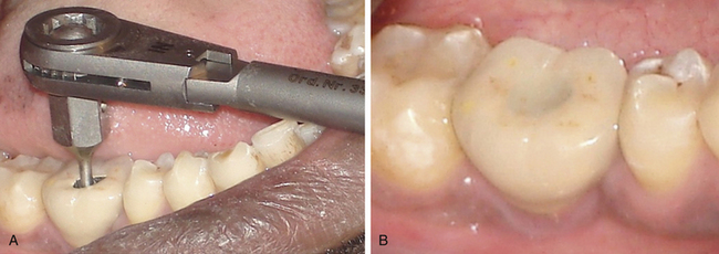
Fig 24.28 Patient reported with connection screw loosening 1 year after implant restoration. (A) An access hole is prepared through the cement-retained prosthesis to locate the connection screw and the screw is re-tightened using the torque ratchet. (B) The access hole is filled using gutta-percha and composite.
Connection screw fracture
Though rare, it is encountered in clinical practise due to several reasons.
Management
The dentist should first try to retrieve the broken screw and if this is not successful, the whole implant can be removed and immediately replaced with another implant of similar or larger dimensions. Thus in cases of connection screw breakage there are various options to solve the problem.
Option-1. The broken screw should be located using the magnification loop or surgical microscope and vibrated using a scaler tip. If the screw gets loosened, it can be removed using a long and sharp probe.
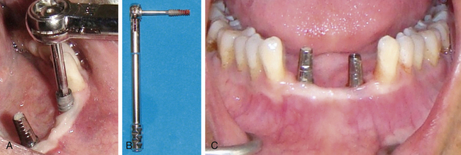
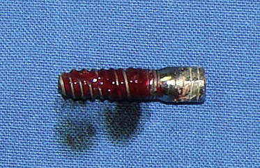
Option-2. The broken screw should be located using the magnification loop or surgical microscope and a horizontal grove should be carefully prepared into the screw, using the high speed turbine. An appropriate screwdriver is then used to unscrew and retrieve the broken screw (Fig 24.29A–J).
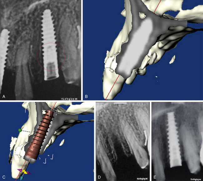
Option-3. If the screw cannot removed by any means, the implant can be removed and immediately replaced by another implant (Fig 24.30A–E).
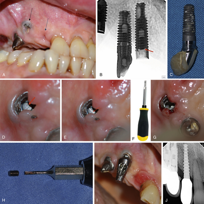
Fig 24.29 (A–C) Fractured connection screw of the implant and postloading failure of the osseointegrated implant from the anterior site because of implant loading with extreme off set occlusal forces. (D and E) The fractured part of the screw is visualized into the implant connection and a high speed turbine with a long straight fissure carbide bur is used to carefully prepare a horizontal groove into the screw under magnification (surgical microscope). (F–H) An appropriate screwdriver is then used to unscrew the broken part of the screw from the implant and (I) the abutment is fixed to the implant. (J) Another implant is inserted at the anterior site and implants are restored.
Implant body fracture
It happens (rarely) if a small diameter implant is inserted for an oversized prosthesis with extreme offset forces. The fractured implant should be removed using the trephine drill and another implant inserted.
Prosthesis fracture
The cause of fracture should be corrected and the prosthesis either repaired or replaced. The hybrid prosthesis which has resin teeth are easy to repair in the mouth using composite resin (Fig 24.31A and B). The screw-retained prosthesis offers an advantage over the cement-retained one, as it can be unscrewed from the implants and easily repaired in the laboratory. The cement-retained prosthesis often needs to be cut down for easy removal from the implant.
Peri-implantitis
Peri-implantitis is defined as an inflammatory reaction with the loss of supporting bone in the tissues surrounding a functioning implant. Peri-implantitis is characterized by bleeding/suppuration on probing, together with loss of supporting bone. Cross-sectional studies have demonstrated that prevalence varies between 28% and 56%. The peri-implantitis lesion exhibits histopathological features that are similar, but not identical, to those in periodontitis. Similar to periodontitis, the treatment of peri-implantitis must be based on infection control. Under these conditions, progression of the disease may be arrested and subsequently, lost peri-implant tissues may be regenerated by bone augmentation and soft tissue grafting procedures.
Summary
The increasing trend of replacing the lost tooth with an implant and its worldwide acceptance, has tremendously increased the number of dentists who are placing and restoring implants. Moreover, several associated procedures like bone augmentation procedures are also being practised to provide this therapy to the maximum number of patients. A comprehensive training is mandatory for the dentist to place and restore implants to minimize postoperative or postloading complications. The mandibular canal is the most important vital structure, which needs to be taken care off during implant insertion, as severe injury to the nerve may result in permanent loss of sensation. The implant should be placed 2–3 mm short of mandibular canal. The magnification factor needs to be calculated to plan the final implant length, if planning with the peri-apical or the panoramic radiograph. The radiograph after partial drilling can also verify the available bone for further drilling and implant placement above the mandibular canal. The anterior loop of the canal should also be taken care of when placing implants in the mandibular premolars and canine region. The implants should also be placed 2 mm short of other vital structures, such as the sinus floor, the nasal floor, etc. An implant with adequate dimensions should be inserted and also positioned at the prosthetically correct position and direction.
All sterilization and disinfection measures should be implemented during implant insertion surgery to avoid post implantation infection. If the implant after insertion has become infected, it should be removed and the site left to heal under antibiotic coverage. Several studies have shown that an oral rinse for 30 s with 0.12% chlorhexidine before the implant surgery, may reduce the chances of post implantation infection to a large extent.
The connection screw of the abutment should be tightened at a moment force of 30–35 Ncm using a mechanical driver (torque ratchet), before fixing the final prosthesis. This avoids the occurrence of screw loosening to a large extent. If the luting cement has spilt out into the peri-implant soft tissue pocket, it should be verified with the radiograph and removed to avoid peri-implantitis.
Postoperative care and follow-up visits after implant therapy are important for long-term maintenance of implant restorations.
Danesh-Meyer M. Diagnosis and management of commonly encountered problems with cemented implant crowns. Dent Pract. 2006:142–148.
Mombelli A., Lang N.P. The diagnosis and treatment of peri-implantitis. Periodontol 2000. 1998;17:63–76.
Park S.-H., Wang H.-L. Implant reversible complications: classification and treatments. Implant Dent. 2005;14:211–220.
Fugazzotto P.A., Wheeler S.L., Lindsay J.A. Success and failure rates of cylinder implants in type IV bone. J Periodontol. 1993;64:1085–1087.
Shin H.I., Sohn D.S. A method of sealing perforated sinus membrane and histological finding of bone substitutes: a case report. Implant Dent. 2005;14:328–335.
Kim S.-G., Mitsugi M., Kim B.-O. Simultaneous sinus lifting and alveolar distraction of the atrophic maxillary alveolus for implant placement: a preliminary report. Implant Dent. 2005;14:344–348.
Ardekian L., Oved-Peleg E., Peled M., et al. The clinical significance of sinus membrane perforation during augmentation of the maxillary sinus. J Oral Maxillofac Surg. 2006;64:277–282.
Proussaefs P., Lozada J., Rohrer M.D., et al. Repair of the perforated sinus membrane with a resorbable collagen membrane: a human study. Int J Oral Maxillofac Impl. 2004;19:413–420.
Jung J.H., Choi B.H., Li J., et al. The effects of exposing dental implants to the maxillary sinus cavity on sinus complications. Oral Surg Oral Med Oral Pathol Oral Radiol Endod. 2006;102:602–605.
Van Steenberghe D., Lekholm U., Bolender C., et al. Applicability of osseointegrated oral implants in the rehabilitation of partial edentulism: a prospective multicenter study on 558 fixtures. Int J Oral Maxillofac Implants. 1990;5:272–281.
Ayangco L., Sheridan P.J. Development and treatment of retrograde peri-implantitis involving a site with a history of failed endodontic and apicoectomy procedures: a series of reports. Int J Oral Maxillofac Implants. 2001;16:412–417.
Nakamura N., Mitsuyasu T., Ohishi M. Endoscopic removal of an implant displaced in the maxillary sinus; a technical note. Int J Oral Maxillofac Surg. 2004;33:195–197.
Varol A., Turker N., Basa S., et al. Endoscopic retrieval of dental implants from the maxillary sinus. Int J Oral Maxillofac Implants. 2006;21:801–804.
Cheung W.W. Risk management in implant dentistry. Hong Kong Dent J. 2005;2:58–60.
Oh T.-J., Joongkyo Y., Wang H.-L. Management of the implant periapical lesions: a case report. Implant Dent. 2003;12:41–46.
Klinge B., Hultin M., Berglundh T. Peri-implantitis. Dent Clin N Am. 2005;49:661–676.
Garg A.K., Reddi S.N., Chacon G.E. The importance of asepsis in dental implantology. Implant Soc. 5, 1994. 8e11
Tolman D.E., Keller E.E. Management of mandibular fractures in patients with endosseous implants. Int J Oral Maxillofac Implants. 1991;6:427–436.
Tiwana K., Morton, Tiwana P.S. Aspiration and ingestion in dental practice: a 10-year institutional review. JADA. 2004;135:1287–1291.
Parel S.M., Funk J.J. The use and fabrication of a self-retaining surgical guide for controlled implant placement; a technical note. Int J Oral Maxillofac Implants. 1991;6:207–210.
Blustein R., Jackson R., Godar D., et al. Use of splint material in the placement of implants. Int J Oral Maxillofac Implants. 1986;1:47–49.
Berglundh T., Persson L., Klinge B. A systematic review of the incidence of biological and technical complications in implant dentistry reported in prospective longitudinal studies of at least 5 years. J Clin Periodontol. 2002;29:197–212.
Shaffer M.D., Juruaz D.A., Haggerty P.C. The effect of periredicular endodontic pathosis on the apical region of adjacent implants. Oral Surg Oral Med Oral Pathol Oral Radiol Endod. 1998;86:578–581.
el Askary A.S., Meffert R.M., Griffin T. Why do dental implants fail? Part I. Implant Dent. 1999;8:173–185.
Worthington P. Injury to the inferior alveolar nerve during implant placement: a formula for protection of the patient and clinician. Int J Oral Maxillofac Implants. 2004;19:731–734.
Sharawy M., Misch C.E., Tehemar S., et al. Heat generation during implant drilling: the significance of motor speed. J Oral Maxillofac Surg. 2002;60:1160–1169.
Albrektsson T., Branemark P.I., Hansson H.A., et al. Osseointegrated titanium implants. Requirements for ensuring a long-lasting direct bone-to-implant anchorage in man. Acta Orthop Scand. 52, 1981. 155e170
Heller A.A., Shankland W.E., II. Alternative to the inferior alveolar nerve block anesthesia when placing mandibular dental implants posterior to the mental foramen. J Oral Implantol. 2001;27:127–133.
Nazarian Y., Eliav E., Nahlieli O. [Hebrew] Nerve injury following implant placement: prevention, diagnosis and treatment modalities. Refuat Hapeh Vehashinayim. 2003;20:44–50.
Kraut R.A., Chahal O. Management of patients with trigeminal nerve injuries after mandibular implant placement. JADA. 2002;133:1351–1354.
Wu P.B., Yung W.C. Factors contributing to implant failure. Hong Kong Dent J. 2005;2:12–18.
McDermott N., Chuang S., Dodson T., et al. Complications of dental implants: identification, frequency, and associated risk factors. Int J Oral Maxillofac Implants. 2003;18:848–855.
Moy P.K., Medina D., Aghaloo T.L., et al. Dental implant failure rates and associated risk factors. Int J Oral Maxillofac Implants. 2005;20:569–577.
Jabero M., Sarment D.P. Advanced surgical guidance technology: a review. Implant Dent. 2006;15:135–142.
Tarnow D.P., Cho S.C., Wallace S.S. The effect of inter-implant distance on the height of inter-implant bone. J Periodontol. 2000;71:546–549.
Tarnow D.P., Magner A.W., Fletcher P. The effect of the distance from the contact point to the crest of bone on the presence or absence of the interproximal dental papilla. J Periodontol. 1992;63:995–996.
de Oliveira R.R., Novaes A., Jr., Taba M., Jr., et al. Influence of inter-implant distance on papilla formation and bone resorption: a clinical-radiographic study in dogs. J Oral Implantol. 2006;32:218–227.
Givol N., Taicher S., Chaushu G., et al. Risk management aspects of implant dentistry. Int J Oral Maxillofac Implants. 2002;17:258–262.
Quirynen M., Gijbels F., Jacobs R. An infected jawbone site compromising successful osseointegration. Periodontol 2000. 2003;33:129–144.
Leong Daylene Jack-Min. Implant Dent. 2011;20(36). 363
Lioubavina-Hack N., Lang N.P., Karring T. Significance of primary stability for osseointegration of dental implants. Clin Oral Impl Res. 2006;17:244–250.
Sussman H.I. Tooth devitalization via implant placement: a case report. Periodontal Clin Investig. 1998;20:22–24.
Ercoli C., Funkenbusch P.D., Lee H.J., et al. The influence of drill wear on cutting efficiency and heat production during osteotomy preparation for dental implants: a study of drill durability. Int J Oral Maxillofac Implants. 2004;19:335–349.
Olson R.A., Fonseca R.J., Osbon D.B., et al. Fractures of the mandible: a review of 580 cases. J Oral Maxillofac Surg. 1982;40:23–28.
Hegedus F., Diecidue R.J. Trigeminal nerve injuries after mandibular implant placement-practical knowledge for clinicians. Int J Oral Maxillofac Implants. 2006;21:111–116.
Day R.H. Microneurosurgery of the injured trigeminal nerve. Oral Maxillofac Surg Knowledge Update. 1994;1:91–116.
Goodacre D.J., Rungcharassaeng K., Kan J.Y., et al. Clinical complications with implants and implant prostheses. J Prosthet Dent. 2003;90:121–132.
Kalpidis C.D., Konstantinidis A.B. Critical hemorrhage in the floor of the mouth during implant placement in the first mandibular premolar position: a case report. Implant Dent. 2005;14:117–124.
Balshi T.J. An analysis and management of fractured implants: a clinical report. Int J Oral Maxillofac Implants. 1996;11(5):660–666.
Goodacre C.J., Kan J.Y., Rungcharassaeng K. Clinical complications of osseointegrated implants. J Prosthet Dent. 1999;81(5):537–552.
Goodacre C.J., Bernal G., Rungcharassaeng K., et al. Clinical complications with implants and implant prostheses. J Prosthet Dent. 2003;90:121–132.
Longoni, Longoni S., Sartori M., et al. Lingual vascular canals of the mandible: the risk of bleeding complications during implant procedures. Implant Dent. 2007;16:131–138.
Chen S., Darby I. Dental implants: maintenance, care and treatment of peri-implant infection. Aust Dent J. 2003;48(4):212–220.
Flanagan D. Important arterial supply of the mandible, control of an arterial hemorrhage, and report of a hemorrhagic incident. J Oral Implantol. 2003;29:165–179.
Bartling R., Freeman K., Kraut R.A. The incidence of altered sensation of the mental nerve after mandibular implant placement. J Oral Maxillofac Surg. 1999;57:1408–1410.
Leonhardt Å, Dahlèn G., Renvert S. Five-year clinical, microbiological, and radiological outcome following treatment of peri-implantitis in man. J Periodontol. 2003;74:1415–1422.
Adell R., Lekholm U., Rockler B., et al. A 15-year study of osseointegrated implants in the treatment of the edentulous jaw. Int J Oral Surg. 10, 1981. 387e416
Schwarz M.S. Mechanical complications of dental implants. Clin Oral Implants Res. 2000;11(Suppl. 1):S156–S158.
Jung R.E., Pjetursson B.E., Glauser R., et al. A systematic review of the 5-year survival and complication rates of implant-supported single crowns. Clin Oral Implants Res. 2008;19:119–130.
Ellies L., Hawker P. The prevalence of altered sensation associated with implant surgery. Int J Oral Maxillofac Implants. 1993;8:674–679.
Misch C.E. Contemporary implant dentistry, 2nd ed. St. Louis: Mosby; 1999. 373
Daylene Jack-Min Leong, et al. Implant Dent. 2011;20(36):363.