Chapter 4 Electrical Therapy
Upon completion of this chapter, you will be able to:
Introduction
Electrical therapies used for the management of a cardiac emergency may include defibrillation, synchronized cardioversion, or transcutaneous pacing. Defibrillation may be performed using an automated external defibrillator (AED) or a manual defibrillator. Using an AED is an important part of basic life support that may be performed by nonmedical personnel and healthcare professionals. Knowing how to use a manual defibrillator and performing synchronized cardioversion or transcutaneous pacing are advanced life support skills.
In this chapter we discuss types of electrical therapies, when electrical therapy is indicated, and the steps needed to safely perform each procedure.
Defibrillation
Definition and Purpose
[Objectives 1, 3]
Defibrillation is the delivery of an electrical current across the heart muscle over a very brief period to terminate an abnormal heart rhythm. Defibrillation is also called unsynchronized countershock or asynchronous countershock, because the delivery of current has no relationship to the cardiac cycle. Indications for defibrillation include pulseless monomorphic VT, sustained polymorphic VT, and VF.
Manual defibrillation refers to the placement of paddles or pads on a patient’s chest, the interpretation of the patient’s cardiac rhythm by a trained healthcare professional, and the healthcare professional’s decision to deliver a shock, if indicated. Automated external defibrillation refers to the placement of paddles or pads on a patient’s chest and the interpretation of the patient’s cardiac rhythm by the defibrillator’s computerized analysis system. Depending on the type of automated external defibrillator (AED) used, the machine will deliver a shock (if a shockable rhythm is detected) or instruct the operator to deliver a shock. AEDs are discussed in more detail later in this chapter. Defibrillation does not “jump start” the heart. The shock attempts to deliver a uniform electrical current of sufficient intensity to depolarize myocardial cells (including fibrillating cells) at the same time, briefly “stunning” the heart. This provides an opportunity for the heart’s natural pacemakers to resume normal activity. When the cells repolarize, the pacemaker with the highest degree of automaticity should assume responsibility for pacing the heart.
Energy, Voltage, and Current
A defibrillator is a device used to deliver a shock to eliminate an abnormal heart rhythm (Figure 4-1). It consists of:
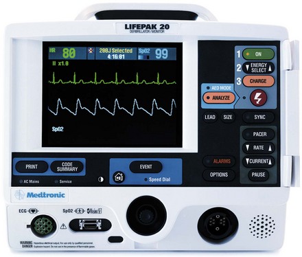
Figure 4-1 A defibrillator is used to deliver an electrical shock to terminate an abnormal heart rhythm.
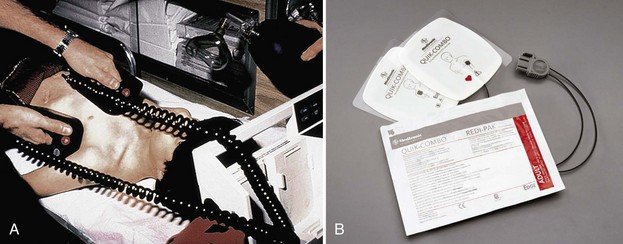
Figure 4-2 A, Hand-held paddles. B, Combination pads have multiple functions. They are applied to a patient’s bare chest for electrocardiogram (ECG) monitoring and then used for defibrillation and synchronized cardioversion (and in some cases, pacing) if necessary.
When the charge button on the defibrillator is pushed, the capacitor charges. Once the capacitor is charged and the shock control is pressed, voltage pushes a flow of electrons (current) to the patient by means of hand-held paddles or combination pads. Current passes through the heart in “waveforms” that travel from one paddle/pad, through the chest, and back to the other paddle/pad over a brief period.
ACLS Pearl
Combination pads have multiple names including “combo pads,” “multi-purpose pads,” “multi-function electrode pads,” “combination electrodes,” “therapy electrodes,” and “self-adhesive monitoring/defibrillation pads.” Not all combination pads are alike. Some pads can be used for defibrillation, synchronized cardioversion, ECG monitoring, and pacing. Others can be used for defibrillation, synchronized cardioversion, and ECG monitoring, but not for pacing. Be sure you are familiar with the capabilities of the pads you are using.
Monophasic Versus Biphasic Defibrillation
[Objective 1]
There are three general types or classes of defibrillation waveforms: monophasic, biphasic, and triphasic.1 Waveforms are classified by whether the current flow delivered is in one direction, two directions, or multiple directions.
When a monophasic waveform is used, current passes through the heart in one (i.e., mono) direction (Figure 4-3). Although few monophasic waveform defibrillators are manufactured today, many are still in use. With biphasic waveforms, energy is delivered in two (i.e., bi) phases. The current moves in one direction for a specified period, stops, and then passes through the heart a second time in the opposite direction during a very short period (i.e., milliseconds) (Figure 4-4).
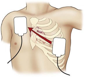
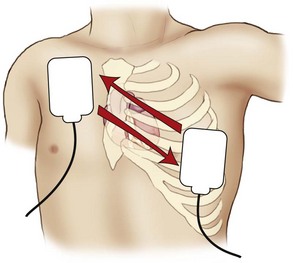
Figure 4-4 With biphasic waveforms, energy is delivered in two phases. The current moves in one direction for a specified period, stops, and then passes through the heart a second time in the opposite direction.
Most AEDs and manual defibrillators sold today make use of biphasic waveform technology. Biphasic defibrillators use either a biphasic truncated exponential (BTE) waveform or a rectilinear biphasic waveform (RBW) (Figure 4-5). The BTE waveform has been used in implantable defibrillator-cardioverters (ICDs) for many years; it was approved for use by the U.S. Food and Drug Administration in 1996 as part of the Heartstream AED, which is now a part of Philips Medical Systems (Seattle, WA). In 1999, Zoll Medical Corporation (Burlington, Mass) announced the development of RBW technology, which was subsequently approved for clinical use by the U.S. Food and Drug Administration.
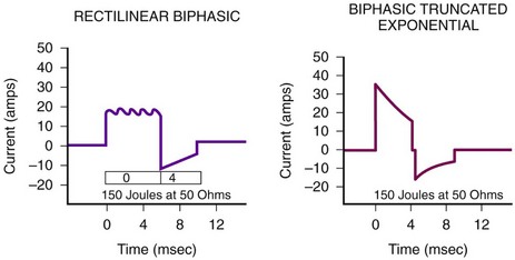
Figure 4-5 Biphasic defibrillators use either a rectilinear biphasic waveform or a biphasic truncated exponential waveform.
Manufacturers of biphasic defibrillators recommend slightly different energy levels specific for their devices. Both escalating (i.e., increasing energy levels) and nonescalating (i.e., no increase in energy level) biphasic waveform defibrillators are available; however, there are insufficient data to recommend one type of device over another. When preparing to deliver electrical therapy to a patient, knowledge of the type of device you are using (i.e., monophasic versus biphasic) and the manufacturer’s recommended energy levels for the dysrhythmia you are treating is essential.
Triphasic and quadriphasic waveforms deliver multidirectional shocks. Future generations of defibrillators may implement this technology.
Transthoracic Impedance
Although the energy selected for defibrillation or cardioversion is expressed in joules, it is current that delivers energy to the patient and depolarizes the myocardium. The energy delivered through the patient’s chest wall is determined by transthoracic impedance. Impedance refers to the resistance to the flow of current. Transthoracic impedance refers to the natural resistance of the chest wall to the flow of current. Impedance is measured in ohms.
When biphasic waveform defibrillation is used, the waveforms compensate for transthoracic impedance to allow for the uniform delivery of energy. The patient’s transthoracic impedance is measured through the paddles or combination pads in contact with the patient’s chest. Transthoracic impedance varies greatly among individuals. Some of the factors known to affect transthoracic impedance are discussed below.
Body Tissue and Hair
The skin surface, fat, bone, and hair can cause significant increases in resistance. It may be difficult to ensure good electrode-to-skin contact in a patient who has a hairy chest. However, if good contact is not ensured, transthoracic impedance will be high and the effectiveness of defibrillation will be reduced.3 There is an increased risk of burns from arcing (i.e., sparks) from electrode to skin and from electrode to electrode; ECG identification and analysis may also be inhibited.
If excessive chest hair is present, quickly clip or shave the hair in the areas of intended electrode placement to ensure proper adhesion of the pads. If this is not feasible (or if a razor is not available), check to see if an extra set of electrodes is available. If so, apply one set to the patient’s chest and then quickly remove them. This should remove some hair and improve electrode-to-skin contact when you apply a second set of pads. However, do not delay defibrillation.
Paddle or Pad Size
Optimum pad sizes for defibrillation and pacing on the basis of patient age and weight vary by manufacturer. Carefully follow all manufacturer instructions.
Studies have shown that adult paddles or pads should be used for patients weighing more than 10 kg (22 lb) (i.e., generally older than 1 year).4-7 For adults, the paddle or pad size ranges from 8 to 12 cm in diameter. Use pediatric paddles or pads for infants and children weighing less than 10 kg (22 lb) or for those whose chests are too small to accommodate standard paddles or pads.8 Generally, use the largest pads that will fit the patient’s chest with at least 1 inch (3 cm) separating the pads. Avoid using pediatric electrodes for adult defibrillation because myocardial injury can occur.9
When applying defibrillation paddles or pads, remove the patient’s clothing and expose his or her chest. Be sure to look for transdermal patches or disks, which may be used to deliver nitroglycerin, nicotine, analgesics, hormones, or antihypertensives. Do not apply paddles or pads directly over the medication patch or disk because the patch may prevent good electrode contact, hindering the delivery of energy from the defibrillation electrode to the heart. A lack of good contact can cause arcing and may cause skin burns.10 If a medication patch, disk, or ointment is located at or near the site of paddle or pad placement, remove it and wipe the area clean (do not use alcohol or alcohol-based cleansers) before applying defibrillation paddles or pads.11
Because some patients wear jewelry in various body locations, take a moment to look for metal body piercings after the patient’s chest is exposed. Although the presence of these materials is not a contraindication to defibrillation, it is possible that their presence can divert the defibrillating current from the myocardium and decrease defibrillation effectiveness. If feasible and if time permits, the metal object should be removed to minimize the potential for burn injuries across the chest.
ACLS Pearl
When biphasic waveform defibrillation is used, the body weight of the patient does not influence the energy delivered.12
Paddle or Pad Position
[Objective 1]
When preparing the skin for paddle or pad placement, do not use alcohol, tincture of benzoin, or antiperspirant. Hand-held paddles or combination pads should be placed on the patient’s bare chest according to the manufacturer’s instructions. Paddles or pads may be labeled according to their intended position on the chest (e.g., sternum/apex, front/back) or according to their polarity (e.g., positive, negative). Studies have shown that the anterolateral, anteroposterior, anterior-left infrascapular, and anterior-right infrascapular paddle/pad positions are equally effective to treat atrial or ventricular dysrhythmias.13
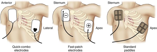
The typical paddle or pad position used during resuscitation is the sternum-apex position, also called the anterolateral or apex-anterior position. This position is often used because the anterior chest is usually easy to get to and placement of the paddles or pads in this position approximates ECG electrode positioning in lead II. Place the sternum paddle or pad lateral to the right side of the patient’s sternum, just below the clavicle. Place the center of the left (apex) paddle or pad in the midaxillary line, lateral to the patient’s left nipple (Figure 4-6). If the patient is a woman, elevate the left breast and place the apex paddle or pad lateral to or underneath the breast. Placing defibrillation paddles or pads directly on breast tissue results in higher transthoracic impedance, reducing current flow.14
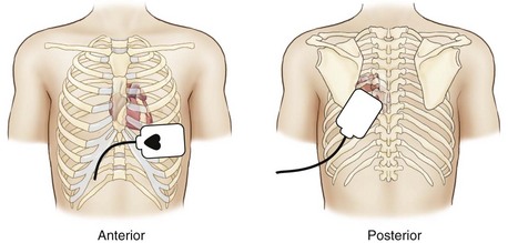
Another common position used for paddle or pad placement is the anterior-posterior position. In this position, one paddle or pad is placed over the patient’s left chest with the upper edge of the pad below the nipple. The other is placed on the back, just below the patient’s left scapula (Figure 4-7). Alternative positions may be considered based on individual patient characteristics.13
Keeping It Simple
In resuscitation situations, precious seconds can be lost when rescuers try to make sure that the “sternum” pad is placed on the sternum and the “apex” pad is placed over the apex of the heart. Delays sometimes occur when rescuers realize that paddles or pads have been placed in reversed positions and then attempt to reposition them to their “proper” location. Reversal of the position of the electrodes is not important during defibrillation, provided the heart is located between them.15
Use of Conductive Material
When using hand-held paddles, the use of gels, pastes, or pregelled defibrillation pads aids the passage of current at the interface between the defibrillator paddles/electrodes and the body surface. Failure to use conductive material results in increased transthoracic impedance, a lack of penetration of current, and burns to the skin surface. Combination pads are pregelled and do not require the application of additional gel to the patient’s chest.
When applying adhesive pads to the patient’s chest, press from one edge of the pad across the entire surface to remove all air and avoid the development of air pockets (Figure 4-8). A hands-free defibrillation cable is used to attach the pads to the monitor/defibrillator.
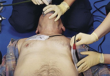
Figure 4-8 When applying adhesive pads to the patient’s chest, press from one edge of the pad across the entire surface to remove all air and avoid the development of air pockets.
When using pregelled pads with hand-held paddles, make sure the pads cover the entire paddle surface to avoid arcing current and potential burns. Do not use saline-soaked gauze or alcohol-soaked pads for defibrillation. Excess saline on the chest may cause arcing and burns. Alcohol-soaked pads may ignite. Do not use gels or pastes (e.g., ultrasound gel) that are not specifically made for defibrillation. The use of improper pastes, creams, gels, or pads can cause burns or sparks and may pose a risk of fire in an oxygen-enriched environment.16 If too much gel is used, the material may spread across the chest wall during resuscitation. This can lead to arcing of the current from one paddle to another and away from the heart, and this can also produce a potentially dangerous spark or burns.
Paddle Pressure
When using hand-held paddles for adult defibrillation, apply firm pressure (i.e., about 25 pounds) to each paddle. This lowers transthoracic impedance by improving contact between the skin surface and the paddles and decreasing the amount of air in the lungs. No pressure is applied when combination pads are used.
Defibrillation Procedure
[Objective 1]
The procedure described below assumes that the patient is an adult and confirmed to be unresponsive, apneic, and pulseless. It also assumes that the patient’s cardiac rhythm is pulseless VT or VF and that a four-person team is available to assist with procedures during the resuscitation effort.
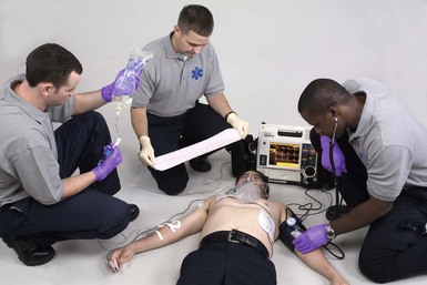
Be sure that the cardiopulmonary resuscitation (CPR) team member continues chest compressions as the defibrillator is readied for use (Figure 4-9). The airway team member should coordinate ventilations with the CPR team member until an advanced airway is placed and its position confirmed.
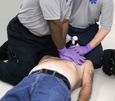
While high-quality CPR continues, instruct the defibrillation team member to expose the patient’s chest and remove any transdermal patches or ointment from the patient’s chest, if present. If hand-held paddles are used, apply conductive material (e.g., gel) to the defibrillator paddles or apply disposable pregelled defibrillator pads to the patient’s bare chest. If combination pads are used, remove the pads from their sealed package. Check the pads for the presence of adequate gel. Attach the pads to the hands-free defibrillation cable, and then attach the combination pads to the patient’s chest in the position recommended by the manufacturer.
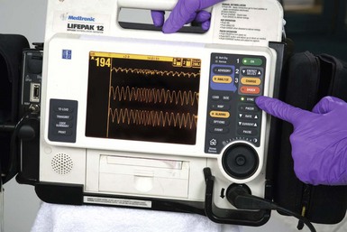
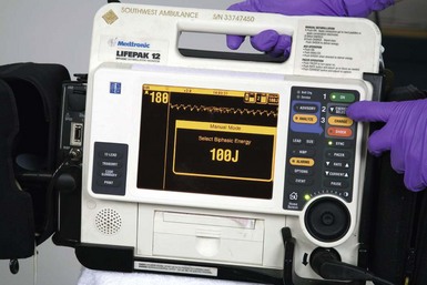
Turn the power to the monitor/defibrillator on and verify the presence of a shockable rhythm on the monitor. Select an appropriate energy level. Use 360 J for all shocks if a monophasic defibrillator is used.13,17 Use the energy levels recommended by the manufacturer for the initial and subsequent shocks if a biphasic defibrillator is used (i.e., 120 to 200 J). If you do not know what the recommended energy levels are, consider defibrillation at the maximal dose.13,17
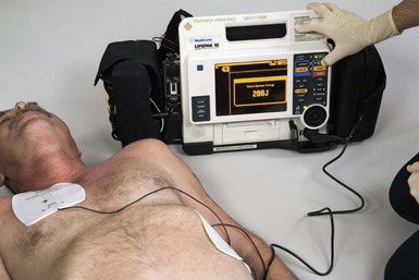
While the defibrillator is readied, instruct the IV/medication team member to prepare the initial drugs that will be used and start an IV after the first shock is delivered. If hand-held paddles are used, instruct the defibrillation team member to place the paddles in their proper positions on the patient’s chest. Be sure that firm downward pressure (about 25 lb) is applied to each paddle. Do not lean on the paddles because they may slip! Charge the defibrillator. If hand-held paddles are used, press the “Charge” button on the machine or the button located on the apex paddle. If combination pads are used, press the “Charge” button on the machine (Figure 4-10).
All team members with the exception of the chest compressor should immediately clear the patient as the machine charges. As the airway team member clears the patient, he or she should be reminded to turn off the oxygen flow. Listen as the machine charges. The sound usually changes when it reaches its full charge. To help minimize interruptions in chest compressions, the person who is performing chest compressions should continue CPR while the machine is charging. When the defibrillator is charged, the chest compressor should immediately clear the patient.
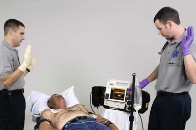
If a shockable rhythm is still present, call “Clear!” Look around you (360 degrees) to be sure everyone—including you—is clear of the patient, the bed, and any equipment connected to the patient (Figure 4-11). Be sure oxygen is not flowing over the patient’s chest. Press the “SHOCK” control to discharge energy to the patient. Release the shock control after the shock has been delivered. Instruct the team to resume chest compressions immediately without pausing for a rhythm or pulse check. Instruct the airway team member to turn on the oxygen and coordinate ventilations with the chest compressor. Instruct the IV/medications team member to establish vascular access and give the patient a vasopressor during CPR. Remember that interruptions in chest compressions must be kept to a minimum throughout the resuscitation effort. Continue CPR for about 2 minutes. After five cycles of CPR (about 2 minutes), recheck the rhythm. If a shockable rhythm is present, charge the defibrillator to a higher dose and then call “Clear!” Check to be certain that everyone is clear and then defibrillate. Resume CPR immediately. While continuing CPR, instruct the IV/medications team member to give an antiarrhythmic (amiodarone or lidocaine if amiodarone is not available). Consider placement of an advanced airway. Use the memory aids PATCH-4-MD or the 5 H’s and 5 T’s to help identify possible reversible causes of the arrest or factors that may be complicating the resuscitation effort. After 2 minutes of CPR, repeat the sequence, beginning with a rhythm check.
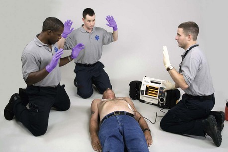
Figure 4-11 Before delivering a shock, call “Clear!” and look around you. Make sure everyone is clear of the patient, bed, and any equipment connected to the patient.
If defibrillation restores an organized rhythm, check for a pulse. If a pulse is present, check the patient’s blood pressure and other vital signs and begin post–cardiac arrest care. If you are not sure if a pulse is present, resume CPR.17 If defibrillation successfully terminates pulseless VT/VF but the rhythm recurs, begin defibrillation at the last energy level used that resulted in successful defibrillation. If a rhythm check reveals a nonshockable rhythm, resume CPR, consider possible causes of the arrest, and give medications and other emergency care as indicated. Continue CPR for 2 minutes before performing another rhythm check.
You Should Know
What If …?
What if you charge the defibrillator and the patient spontaneously converts to a rhythm that is not shockable or an organized rhythm before the shock is delivered? Check the operating instructions that accompany the defibrillator you are using for a definitive answer to this question. In most cases, the machine will disarm (i.e., internally remove the stored energy) if the discharge buttons are not pressed within 60 seconds. The machine will also disarm if you change the selected energy or press the energy selector to remove the charge.
What energy should be used if you deliver a shock that eliminates pulseless VT/VF and then the rhythm recurs? If defibrillation terminates pulseless VT/VF that then recurs, defibrillate at the last successful energy setting.17
What if the rhythm on the monitor looks like a “flat line?” If the rhythm appears to be asystole, make sure the power to the monitor is turned on, check the lead and cable connections, make sure the correct lead is selected, and turn up the gain (i.e., the ECG size) on the monitor. If the patient is unresponsive, not breathing, or only gasping and has no pulse, begin CPR immediately.
What if the patient has a permanent pacemaker or an ICD? An ICD is typically placed subcutaneously in the left upper quadrant of the patient’s abdomen or the left pectoral area (Figure 4-12). It can deliver a range of therapies (also called tiered-therapy) including defibrillation, antitachycardia (i.e., “overdrive”) pacing, synchronized cardioversion, and bradycardia pacing, depending on the dysrhythmia detected and how the device is programmed (Figure 4-13). A physician determines the appropriate therapies for each patient. Depending on the manufacturer, the ICD may deliver a maximum of six shocks for VF. About 2 J are delivered at the body surface when the ICD discharges internally. Rescuers in contact with the patient may feel a tingling sensation when the ICD delivers a shock. Although the energy is enough to be felt by the rescuer, it is not enough to cause physiologic harm. If the ICD is delivering shocks, wait 30 to 60 seconds for the ICD to complete the treatment cycle before attaching an AED. When defibrillating or cardioverting a patient with a permanent (implanted) pacemaker or an ICD, be careful to not place the defibrillator paddles or combination pads directly over the device. The anterior-posterior and anterolateral paddle or pad positions are considered acceptable in these patients.13 Although placement of paddles or pads should not delay defibrillation, defibrillator paddles or combination pads should ideally be placed at least 3 inches (8 cm) from the pulse generator (there will be a bulge under the patient’s skin).13 Because some of the defibrillation current flows down the pacemaker leads, a patient who has a permanent pacemaker or ICD should have the device checked to ensure proper function after defibrillation.
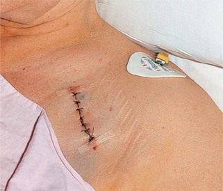
Figure 4-12 Site of implantation of a permanent pacemaker or automatic implantable cardioverter-defibrillator (ICD). The device is usually implanted in the left pectoral region, but it may be placed elsewhere if necessary.
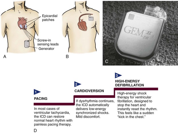
Figure 4-13 A, Placement of an implantable cardioverter defibrillator (ICD) and epicardial lead system. The generator is placed in a subcutaneous “pocket” in the left upper abdominal quadrant. The epicardial screw-in sensing leads monitor the heart rhythm and connect to the generator. If a life-threatening dysrhythmia is sensed, the generator can pace-terminate the dysrhythmia or deliver electrical cardioversion or defibrillation through the epicardial patches. With this system, the leads and patches must be placed during an open chest procedure (sternal surgery or thoracotomy). B, In the transvenous lead system, open chest surgery is not required. The pacing, cardioversion, and defibrillation functions are all contained in a lead (or leads) inserted into the right atrium and ventricle. New generators are small enough to place in the pectoral region. C, An example of a dual-chamber ICD (Medtronic Gem II DR) with tiered therapy and pacing capabilities. D, Tiered therapy is designed to use increasing levels of intensity to terminate ventricular dysrhythmias.
Automated External Defibrillators
Automated External Defibrillator Features
An AED is an external defibrillator that has a computerized cardiac rhythm analysis system. AEDs are easy to use. Voice prompts and visual indicators guide the user through a series of steps that may include defibrillation. When the adhesive electrodes are attached to the patient’s chest, the AED examines the patient’s cardiac rhythm and analyzes it. Some AEDs require the operator to press an “analyze” control to initiate rhythm analysis whereas others automatically begin analyzing the patient’s cardiac rhythm when the electrode pads are attached to the patient’s chest. Safety filters check for false signals (e.g., radio transmissions, poor electrode contact, 60-cycle interference, loose electrodes).
When the AED analyzes the patient’s cardiac rhythm, it “looks” at multiple features of the rhythm, including the QRS width, rate, and amplitude. If the AED detects a shockable rhythm, it then charges its capacitors. In addition to recommending a shock for VF, AEDs will recommend a shock for monomorphic VT and polymorphic VT. The preset rate for shockable VT varies depending on the AED. For example, some manufacturers set the shockable VT rate for adults at greater than 150 beats/min. Others set the rate at greater than 120 beats/min.
If the machine is a fully automated AED and a shockable rhythm is detected, it will signal everyone to stand clear of the patient and then deliver a shock by means of the adhesive pads that were applied to the patient’s chest. If the machine is a semiautomated AED and a shockable rhythm is detected, it will instruct the AED operator (by means of voice prompts and visual signals) to press the shock control to deliver a shock.
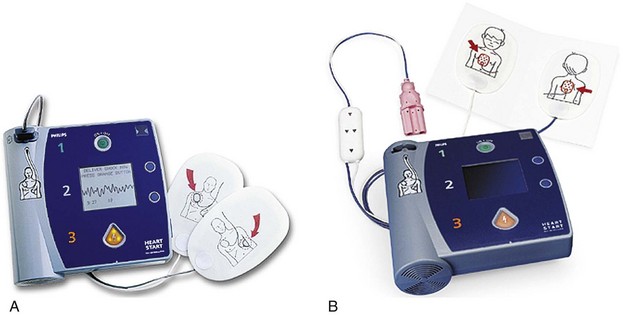
Figure 4-14 A, An automated external defibrillator (AED). B, This defibrillation pad and cable system reduces the energy delivered by a standard AED to that appropriate for a child.
Use a standard AED for a patient who is unresponsive, apneic, pulseless, and 8 years old or older. If the patient is between 1 and 8 years old and a pediatric attenuator is unavailable for the AED, use a standard AED. For infants, defibrillation with a manual defibrillator is preferred. If a manual defibrillator is not available, an AED equipped with a pediatric attenuator is desirable. If neither is available, use a standard AED.13
Automated External Defibrillator Operation
[Objective 1]
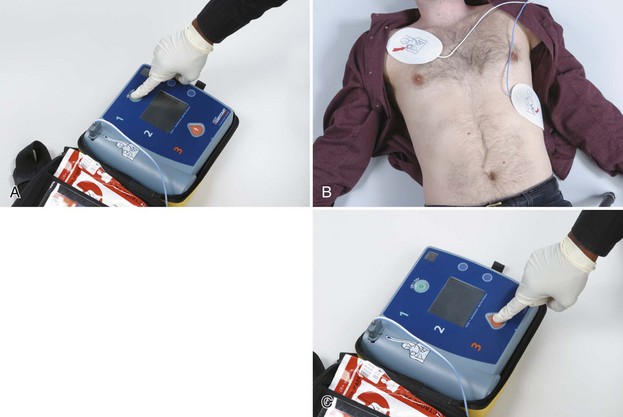
Figure 4-15 AED operation. A, Turn on the power to the AED. B, Attach the AED pads to the patient’s bare chest as directed on the pads. Allow the AED to analyze the patient’s rhythm. Do not touch the patient while the rhythm is being analyzed. C, If the AED detects a shockable rhythm, clear the area surrounding the patient. Make sure everyone is clear of the patient, the bed, and any equipment connected to the patient. Make sure oxygen is not flowing over the patient’s chest. Press the “Shock” button when prompted to do so by the AED.
Special Considerations
If the patient has a pacemaker or ICD, an AED may be used; but the AED pads should be placed at least 3 inches (8 cm) from the implanted device. If an ICD is in the process of delivering shocks to the patient, allow it about 30 to 60 seconds to complete its cycle.
If a transdermal medication patch is present on the patient’s chest, do not attempt to defibrillate through it. Remove the patch and wipe the area clean before applying the AED pads if doing so will not delay defibrillation.
AEDs can be used when the patient is lying on snow or ice. If an unresponsive patient is lying in water or the patient’s chest is covered with water, it may be reasonable to remove the victim from the water and quickly wipe the chest before applying the AED pads and attempting defibrillation.13
If the patient has excessive chest hair, the AED pads may not adhere to the patient’s chest resulting in a “check electrodes” message from the AED. If pressing down firmly on each AED pad does not correct the problem, promptly shave the excess hair from the area of the chest where the AED pads will be placed if a razor is available (a razor is often stored in the AED case for this purpose) and then apply a new set of AED pads. If a razor is not available, quickly remove the AED pads, which should also remove some of the chest hair, and apply a second set of AED pads. Ensure that chest compressions are not interrupted and defibrillation is not delayed.
Maintenance
Specific AED maintenance should be performed according to the manufacturer’s recommendations. Newer AEDs require minimal maintenance because they perform automated self-checks. AEDs usually self-test their internal circuitry, battery status, ECG electronics, defibrillator electronics, and microprocessor electronics. The frequency with which automatic self-tests occur varies by the device. Some AEDs perform daily self-tests, while others occur weekly. Additional self-tests usually occur when batteries are installed and when the AED is powered on. Manual self-tests can be performed at any time.
Synchronized Cardioversion
Description and Purpose
[Objectives 2, 3]
Synchronized cardioversion is a type of electrical therapy during which a shock is timed or programmed for delivery during ventricular depolarization (i.e., QRS complex). When the “sync” control is pressed, a synchronizing circuit in the machine searches for the highest (i.e., R wave deflection) or deepest (i.e., QS deflection) part of the QRS complex and delivers the shock a few milliseconds after this portion of the QRS. The delivery of a shock during this portion of the cardiac cycle reduces the potential for the delivery of current during ventricular repolarization, which includes the vulnerable period of the T wave (i.e., relative refractory period).
Because the machine must be able to detect a QRS complex so that it can “sync,” synchronized cardioversion is used to treat rhythms that have a clearly identifiable QRS complex and a rapid ventricular rate (e.g., some narrow-QRS tachycardias, monomorphic VT). Synchronized cardioversion is not used to treat disorganized rhythms (e.g., polymorphic VT) or those that do not have a clearly identifiable QRS complex (e.g., VF).
Procedure
[Objectives 2, 3]
Before performing synchronized cardioversion, take appropriate standard precautions and verify that the procedure is indicated (Figure 4-16). Identify the rhythm on the cardiac monitor. Print an ECG strip to document the patient’s rhythm, and assess the patient for serious signs and symptoms from the tachycardia. Make sure suction and emergency medications are available. Give supplemental oxygen, if indicated, and start an IV. If the patient is awake, explain the procedure.
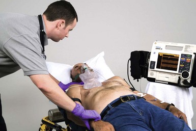
Figure 4-16 Before performing synchronized cardioversion, take appropriate standard precautions and verify that the procedure is indicated.
Remove clothing from the patient’s upper body (Figure 4-17). With gloves, remove nitroglycerin paste or transdermal patches from the patient’s chest if present and quickly wipe away any medication residue. If present, remove excessive hair from the sites where the paddles or electrodes will be placed. Clip or shave hair if necessary (and if time permits). Avoid cutting the skin. Do not apply alcohol, tincture of benzoin, or antiperspirant to the skin.
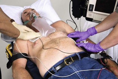
Figure 4-17 Remove clothing, transdermal patches, and medication residue from the patient’s upper body. Place pregelled defibrillation pads (if using hand-held paddles) on the patient’s chest at this time. If using multipurpose adhesive electrodes, place them in proper position on the patient’s bare chest according to the defibrillator manufacturer’s instructions.
Turn the power to the defibrillator on. If using standard paddles, you must use defibrillation gel or defibrillation gel pads between the paddle electrode surface and the patient’s skin. Place pregelled defibrillation pads on the patient’s chest at this time. If using combination pads, place them in proper position on the patient’s bare chest.
Press the “sync” control on the defibrillator (Figure 4-18). Select a lead with an optimum QRS complex amplitude (either positive or negative) and no artifact. Make sure the machine is marking or flagging each QRS complex and that no artifact is present. The sense marker should appear near the middle of each QRS complex. If sense markers do not appear or are seen in the wrong place (e.g., on a T wave), adjust the ECG size, or select another lead.
If the patient is awake and time permits, administer sedation per local protocol or physician orders, unless contraindicated. Make sure the machine is in “sync” mode and then select the appropriate energy level on the defibrillator (Figure 4-19).
Charge the defibrillator and recheck the ECG rhythm. If using standard paddles, place the paddles on the pregelled defibrillator pads on the patient’s chest and apply firm pressure. If the rhythm is unchanged, call “Clear!” and look around you (Figure 4-20). Make sure everyone is clear of the patient, the bed, and any equipment connected to the patient. Make sure oxygen is not flowing over the patient’s chest. If the area is clear, press and hold the shock controls until the shock is delivered. A slight delay may occur while the machine detects the next QRS complex. Release the shock control after the shock has been delivered.
Reassess the rhythm and the patient (Figure 4-21). If the tachycardia persists, make sure the machine is in sync mode before delivering another shock. If the rhythm changes to VF, confirm that the patient has no pulse while another team member quickly verifies that all electrodes and cable connections are secure. If no pulse is present, turn off the “sync” control, and defibrillate. See Table 4-1 for a summary of defibrillation and cardioversion.
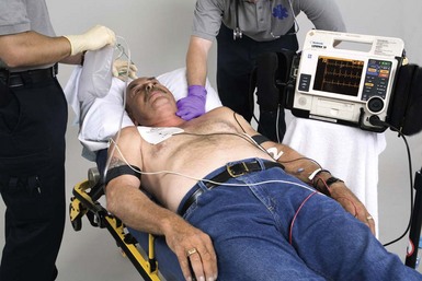
TABLE 4-1 Defibrillation and Cardioversion Summary
| Type of Shock | Rhythm | Recommended Energy Levels13 |
|---|---|---|
| Defibrillation* | Pulseless VT/VF Sustained polymorphic VT |
Varies depending on the device used |
| Synchronized cardioversion* | Unstable narrow-QRS tachycardia | The biphasic dose is typically 50 J to 100 J initially, increase in a stepwise fashion if the initial shock fails. |
| Unstable atrial flutter | The biphasic dose is typically 50 J to 100 J initially, increase in a stepwise fashion if the initial shock fails. | |
| Unstable atrial fibrillation | The biphasic dose is typically 120 J to 200 J initially (biphasic), increase in a stepwise fashion if the initial shock fails; begin with 200 J if using monophasic energy, and increase if unsuccessful. | |
| Unstable monomorphic VT | The biphasic dose is typically 100 J initially; it is reasonable to increase in a stepwise fashion if the initial shock fails. |
* Use energy levels recommended by the device manufacturer.
ACLS Pearl
Defibrillation and Cardioversion
Special Considerations
Remove supplemental oxygen sources from the area of the patient’s bed before defibrillation and cardioversion attempts are made and place them at least 3.5 to 4 feet away from the patient’s chest. Examples of supplemental oxygen sources include masks, nasal cannulae, resuscitation bags, and ventilator tubing. Case reports exist that describe instances of fires being ignited by sparks from poorly applied defibrillator paddles that ignited flammable materials in the presence of an oxygen-enriched atmosphere.16,18-20 In most cases, fires resulted when high flow oxygen delivery systems (i.e., 10 L/min or more) had been left next to the patient while defibrillation was attempted. There are presently no case reports of fires caused by sparking when defibrillation was performed using adhesive pads.
To enhance safety during defibrillation and cardioversion attempts:
Possible Complications
Possible complications of electrical therapy include the following:
Possible Errors
Possible errors that may occur during the delivery of electrical therapy include the following:
Transcutaneous Pacing
Transcutaneous pacing (TCP) is the use of electrical stimulation through pacing pads positioned on a patient’s torso to stimulate contraction of the heart. TCP is also called temporary external pacing or noninvasive pacing.
Although TCP is a type of electrical therapy, the current delivered is considerably less than that used for cardioversion or defibrillation. The energy levels selected for cardioversion or defibrillation are indicated in joules. The stimulating current selected for TCP is measured in milliamperes (mA); the range of output current of a transcutaneous pacemaker varies depending on the manufacturer. For example, the range of output current for one brand of transcutaneous pacemaker is 0 to 140 mA. The range for another brand is 0 to 200 mA. Most transcutaneous pacemakers have a heart rate selection that ranges from 30 to 180 beats/min. You must be familiar with your equipment before you need to use it.
TCP requires attaching two pacing electrodes to the skin surface of the patient’s outer chest wall. The pacing pads used during TCP function as a bipolar pacing system. The electrical signal exits from the negative terminal on the machine (and subsequently the negative electrode) and passes through the chest wall to the heart.
Indications
[Objective 1]
TCP is indicated for symptomatic bradycardias unresponsive to atropine therapy or when atropine is not immediately available or indicated. It may also be used as a bridge until transvenous pacing can be accomplished or until the cause of the bradycardia is reversed (as in cases of drug overdose or hyperkalemia). Whether or not TCP is effective, the patient should be prepared for transvenous pacing and expert consultation sought.17
Procedure
[Objective 4]
Take appropriate standard precautions and verify that the procedure is indicated (Figure 4-22). Place the patient on oxygen, if indicated. Assess the patient’s vital signs, establish IV access, and apply ECG electrodes. Identify the rhythm on the cardiac monitor. Record a rhythm strip and verify the presence of a paceable rhythm. Continuous monitoring of the patient’s ECG is essential throughout the procedure.
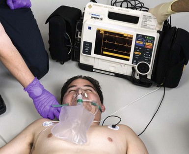
Figure 4-22 Before performing transcutaneous pacing, take appropriate standard precautions and verify that the procedure is indicated.
Apply adhesive pacing pads to the patient according to the manufacturer’s recommendations (Figure 4-23). Do not place the pads over open cuts, sores, or metal objects. The pacing pads should fit completely on the patient’s chest. Have a minimum of 1 to 2 inches of space between electrodes or pads, and not overlap bony areas of the sternum, spine, or scapula.
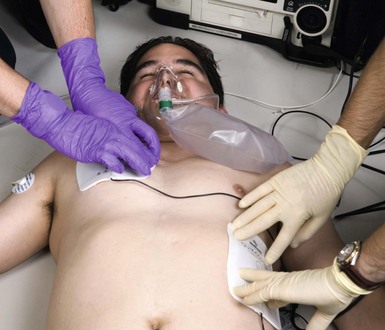
Figure 4-23 Apply adhesive pacing pads to the patient according to the manufacturer’s recommendations.
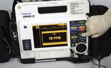
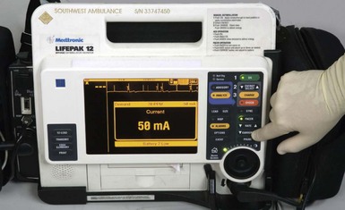
Connect the pacing cable to the pacemaker and to the adhesive pads on the patient. Turn the power to the pacemaker on. Set the pacing rate to the desired number of paced pulses per minute (ppm). In an adult, set the initial rate at a nonbradycardic rate between 60 and 80 pulses/min (Figure 4-24). After the rate has been regulated, start the pacemaker (Figure 4-25). Increase the stimulating current (i.e., output or milliamperes) slowly but steadily until pacer spikes are visible before each QRS complex (i.e., capture). This control is usually labeled “Current,” “Pacer output,” or “mA.” Because transcutaneous pacing is painful in conscious patients, sedation or analgesia may be needed to minimize the patient’s discomfort associated with this procedure, particularly with currents of 50 mA or more. Give the patient medications according to local protocol or physician orders.
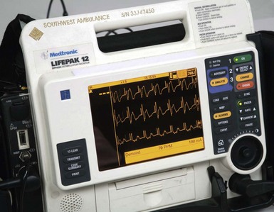
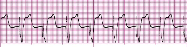
Watch the cardiac monitor closely for electrical capture. This usually is seen in the form of a wide QRS and a broad T wave (Figures 4-26 and 4-27). In some patients, electrical capture is less obvious; it may only be indicated as a change in the shape of the QRS.
Assess mechanical capture (Figure 4-28). Mechanical capture occurs when pacing produces a response that can be measured, such as a palpable pulse and blood pressure. Assess mechanical capture by assessing the patient’s right upper extremity or right femoral pulses. Avoid assessment of pulses in the patient’s neck or on the patient’s left side; this helps minimize confusion between the presence of an actual pulse and skeletal muscle contractions caused by the pacemaker. After capture is achieved, continue pacing at an output level slightly higher (approximately 2 mA) than the threshold of initial electrical capture. For example, if the monitor reveals 100% capture when you reached 80 mA, your final setting would be 82 mA.
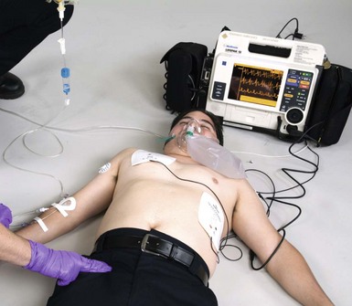
Figure 4-28 Assess mechanical capture by assessing the patient’s right upper extremity or right femoral pulses.
Assess the patient’s level of responsiveness, SpO2, and blood pressure (Figure 4-29). Closely monitor the patient and assess the skin for irritation where the pacing pads have been applied. Document and record the ECG rhythm. Documentation should include the date and time pacing was initiated (including baseline and pacing rhythm strips), the current required to obtain capture, the pacing rate selected, the patient’s responses to electrical and mechanical capture, medications administered during the procedure, and the date and time pacing was terminated, if applicable.
Limitations
The main limitation of TCP is patient discomfort. The discomfort is proportional to the intensity of skeletal muscle contraction and the direct electrical stimulation of cutaneous nerves. The degree of discomfort varies with the device used and the stimulating current required to achieve capture.
Capture may be difficult to achieve or it may be inconsistent for some patients. Increased stimulating current may be required for patients with increased chest wall muscle mass, chronic obstructive pulmonary disease, pleural effusions, dilated cardiomyopathy, hypoxia, or metabolic acidosis because of the extremely high current thresholds required.21
From Flynn, JB: Introduction to critical care skills. St. Louis, 1993, Mosby-Year Book.
ACLS Pearl
Patient Responses to Current with Transcutaneous Pacing
| Output (mA)* | Response |
|---|---|
| 20 | Prickly sensation on skin |
| 30 | Slight thump on chest |
| 40 | Definite thump on chest |
| 50 | Coughing |
| 60 | Diaphragm pacing and coughing |
| 70 | Coughing and knock on chest |
| 80 | More uncomfortable than 70 mA |
| 90 | Strong, painful knock on chest |
| 100 | Leaves bed because of pain |
Possible Complications
[Objective 4]
Complications of TCP include the following:
Pacemaker Malfunction
Failure to Pace
Failure to pace, which is also referred to as failure to fire, is a pacemaker malfunction that occurs when the pacemaker fails to deliver an electrical stimulus or when it fails to deliver the correct number of electrical stimulations per minute. Failure to pace is recognized on the ECG as an absence of pacemaker spikes (although the patient’s intrinsic rate is less than that of the pacemaker) and a return of the underlying rhythm for which the pacemaker was implanted. Patient signs and symptoms may include syncope, chest pain, bradycardia, and hypotension.
Causes of failure to pace include battery failure, fracture of the pacing lead wire, displacement of the electrode tip, pulse generator failure, a broken or loose connection between the pacing lead and the pulse generator, electromagnetic interference, and the sensitivity setting being set too high. Treatment may include adjusting the sensitivity setting, replacing the pulse generator battery, replacing the pacing lead, replacing the pulse generator unit, tightening connections between the pacing lead and pulse generator, performing an electrical check, and/or removing the source of electromagnetic interference.
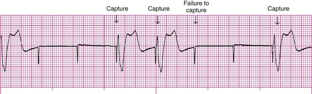
Failure to Capture
Failure to capture is the inability of a pacemaker stimulus to depolarize the myocardium. It is recognized on the ECG by visible pacemaker spikes that are not followed by P waves (i.e., atrial pacing) or QRS complexes (i.e., ventricular pacing) (Figure 4-30). Patient signs and symptoms may include fatigue, bradycardia, and hypotension.
Causes of failure to capture include battery failure, fracture of the pacing lead wire, displacement of pacing lead wire (this is a common cause), perforation of the myocardium by a lead wire, edema or scar tissue formation at the electrode tip, output energy (mA) being set too low (this is a common cause), and an increased stimulation threshold because of medications, electrolyte imbalance, or increased fibrin formation on the catheter tip.
Treatment may include repositioning the patient, slowly increasing the output setting (mA) until capture occurs or the maximum setting is reached, replacing the pulse generator battery, replacing or repositioning of the pacing lead, or surgery.
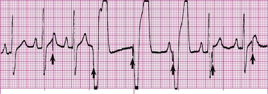
Failure to Sense
Sensitivity is the extent to which a pacemaker recognizes intrinsic electrical activity. Failure to sense occurs when the pacemaker fails to recognize spontaneous myocardial depolarization (Figure 4-31). This pacemaker malfunction is recognized on the ECG by pacemaker spikes that follow too closely behind the patient’s QRS complexes (i.e., earlier than the programmed escape interval). Because pacemaker spikes occur when they should not, this type of pacemaker malfunction may result in pacemaker spikes that fall on T waves (this is R-on-T phenomenon) and in competition between the pacemaker and the patient’s own cardiac rhythm. The patient may complain of palpitations or skipped beats. R-on-T phenomenon may precipitate VT or VF.
Causes of failure to sense include battery failure, fracture of the pacing lead wire, displacement of the electrode tip (this is the most common cause), decreased P wave or QRS voltage, circuitry dysfunction (i.e., the generator is, unable to process the QRS signal), increased sensing threshold as a result of edema or fibrosis at the electrode tip, antiarrhythmic medications, severe electrolyte disturbances, and myocardial perforation. Treatment may include increasing the sensitivity setting, replacing the pulse generator battery, or replacing or repositioning the pacing lead. A summary of the electrical therapies discussed in this chapter is shown in Table 4-2.
TABLE 4-2 Electrical Therapy Summary
| Type of Electrical Therapy | Rhythm | Recommended Energy Levels |
|---|---|---|
| Defibrillation* | Pulseless VT/VF Sustained polymorphic VT |
Varies depending on the device used: |
| Synchronized cardioversion* | Unstable narrow-QRS tachycardia | The biphasic dose is typically 50 J to 100 J initially; increase in a stepwise fashion if the initial shock fails. |
| Unstable atrial flutter | The biphasic dose is typically 50 J to 100 J initially; increase in a stepwise fashion if the initial shock fails. | |
| Unstable atrial fibrillation | The biphasic dose is typically 120 J to 200 J initially; increase in a stepwise fashion if the initial shock fails; begin with 200 J if using monophasic energy, and increase if unsuccessful | |
| Unstable monomorphic VT | The biphasic dose is typically 100 J initially; it is reasonable to increase in a stepwise fashion if the initial shock fails | |
| Transcutaneous pacing | Symptomatic bradycardia |
Identify the choice that best completes the statement or answers the question.
1 Huang J, KenKnight BH, Rollins DL, et al. Ventricular defibrillation with triphasic waveforms. Circulation. 2000;101(11):1324-1328.
2 White RD. New concepts in transthoracic defibrillation. Emerg Med Clin N Am. 2002;20:785-807.
3 Bissing JW, Kerber RE. Effect of shaving the chest of hirsute subjects on transthoracic impedance to self-adhesive defibrillation electrode pads. Am J Cardiol. 2000;86(5):587-589. A10
4 Atkins DL, Sirna S, Kieso R, et al. Pediatric defibrillation: importance of paddle size in determining transthoracic impedance. Pediatrics. 1988;82(6):914-918.
5 Atkins DL, Kerber RE. Pediatric defibrillation: current flow is improved by using “adult” electrode paddles. Pediatrics. 1994;94(1):90-93.
6 Samson RA, Atkins DL, Kerber RE. Optimal size of self-adhesive preapplied electrode pads in pediatric defibrillation. Am J Cardiol. 1995;75(7):544-545.
7 Killingsworth CR, Melnick SB, Chapman FW, et al. Defibrillation threshold and cardiac responses using an external biphasic defibrillator with pediatric and adult adhesive patches in pediatric-sized piglets. Resuscitation. 2002;55(2):177-185.
8 Kleinman ME, Chameides L, Schexnayder SM, et al. Part 14: pediatric advanced life support: 2010 American Heart Association guidelines for cardiopulmonary resuscitation and emergency cardiovascular care. Circulation. 2010;122(Suppl 3):S876-S908.
9 Dahl CF, Ewy GA, Warner ED, Thomas ED. Myocardial necrosis from direct current countershock. Effect of paddle electrode size and time interval between discharges. Circulation. 1974 Nov;50(5):956-961.
10 Panacek EA, Munger MA, Rutherford WF, Gardner SF. Report of nitropatch explosions complicating defibrillation. Am J Emerg Med. 1992;10(2):128-129.
11 Wrenn K. The hazards of defibrillation through nitroglycerin patches. Ann Emerg Med. 1990;19(11):1327-1328.
12 McGlinch BP, White RD. Cardiopulmonary resuscitation: basic and advanced life support. In Miller RD, editor: Miller’s Anesthesia, ed 7, Philadelphia: Churchill Livingstone, 2009.
13 Link MS, Atkins DL, Passman RS, et al. Part 6: electrical therapies: automated external defibrillators, defibrillation, cardioversion, and pacing: 2010 American Heart Association guidelines for cardiopulmonary resuscitation and emergency cardiovascular care. Circulation. 2010;122(Suppl 3):S706-S719.
14 Pagan-Carlo LA, Spencer KT, Robertson CE, et al. Transthoracic defibrillation: importance of avoiding electrode placement directly on the female breast. J Am Coll Cardiol. 1996 Feb;27(2):449-452.
15 Olsovsky MR, Shorofsky SR, Gold MR. The effect of shock configuration and delivered energy on defibrillation impedance. Pacing Clin Electrophysiol. 1999;22(1 Pt 2):165-168.
16 Hummel RS3rd, Ornato JP, Weinberg SM, Clarke AM. Spark-generating properties of electrode gels used during defibrillation. A potential fire hazard. JAMA. 1988;260(20):3021-3024. 25
17 Neumar RW, Otto CW, Link MS, et al. Part 8: adult advanced cardiovascular life support: 2010 American Heart Association guidelines for cardiopulmonary resuscitation and emergency cardiovascular care. Circulation. 2010;122(Suppl 3):S729-S767.
18 Miller PH. Potential fire hazard in defibrillation. JAMA. 1972;221(2):192.
19 Lefever J, Smith A: Risk of fire when using defibrillation in an oxygen enriched atmosphere, Medical Devices Agency 1995 (Feb). MDA SN95/03.
20 Theodorou AA, Gutierrez JA, Berg RA. Fire attributable to a defibrillation attempt in a neonate. Pediatrics. 2003 Sep;112(3 Pt 1):677-679.
21 Wilson JG, Macgregor DC, Goldman BS, et al. Factors affecting patient recovery following pacemaker implantation. Clin Prog Pacing Electrophysiology. 1984;2(6):554.
22 Beland MJ, Hesslein PS, Finlay CD, et al. Noninvasive transcutaneous cardiac pacing in children. Pacing Clin Electrophysiol. 1987 Nov;10(6):1262-1270.