Compensating Filters
Introduction
In most cases, radiography is accomplished using a single exposure technique for a given body structure. However, some structures contain areas of significantly varied tissue thickness and density that must be shown on a single image. These body parts present special challenges for showing all anatomic structures with an acceptable range of brightness levels. Often, two exposures must be made of these body structures, doubling radiation exposure to the patient.
Typically, if one exposure is used, a technique is selected to penetrate adequately the densest area of anatomy. With digital radiography systems, automatic rescaling can compensate for some of the extreme differences in image receptor (IR) exposure in the image field, but the resulting image may still demonstrate significant differences in brightness between anatomic structures of widely varying tissue densities. Images that appear low in contrast, contain high noise, or show artifacts can result. Clinical experience shows that compensating filters improve digital images.
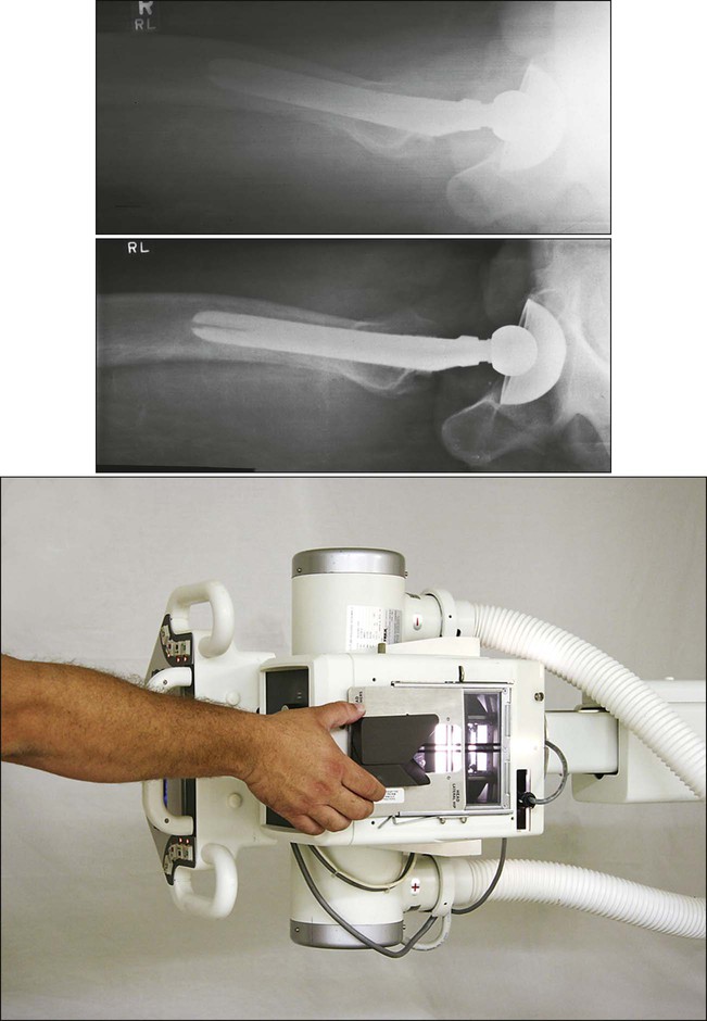
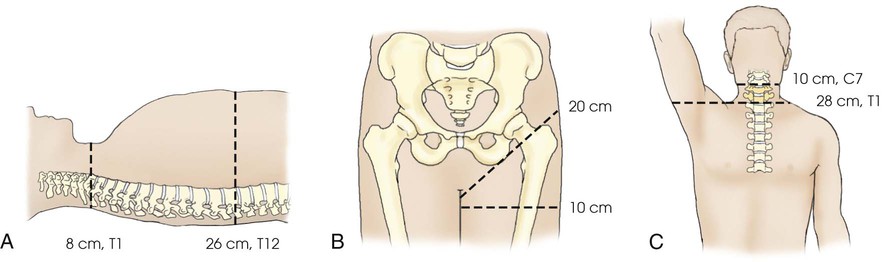
Examples of x-ray projections that need to be able to demonstrate significantly varied tissue densities include the anteroposterior (AP) projection of the thoracic spine, the axiolateral projection (Danelius-Miller method) of the hip, and the lateral cervicothoracic region (swimmer's technique) (Fig. 2-1). Exposure of these structures with a uniformly intense x-ray beam results in the production of an image with areas of underexposed or overexposed anatomy. To compensate for these variations in tissue density, specially designed attenuating devices called compensating filters can be placed between the radiographic tube and the IR. The resulting attenuated beam more appropriately exposes the various tissue densities of the anatomy and reveals greater anatomic detail. Equally important, the filter reduces the entrance skin exposure and thus the absorbed dose to some of the organs in the body (Fig. 2-2).
The technique of compensatory filtration was first applied by Pfahler in 1905,1 not long after x-rays were first discovered. Pfahler used wet shoe leather as the filter by wrapping it around a patient's arm. Compensating filters of one type or another have been in use since that time. Some of the most common filters in use today are shown in Fig. 2-3. These filters can be used with all types of IRs to improve the image quality of various anatomic areas. With most digital systems, filters are necessary to obtain a diagnostic image of a body part with extreme differences in density. In addition, radiation exposure to the patient is reduced through elimination of extra exposures needed to show all of the anatomy and through the beam-hardening effect of the attenuating filter. The increasing thickness of the filter over the thinner body part also acts to reduce exposure.

Appropriate use of radiographic compensating filters is an important addition to the radiographer's skill set. The radiographer determines whether to use a filter based on an assessment of the patient and determines the type and exact position of the filter. This determination is made while the patient is positioned. Radiographic projections of the lateral hip and the lateral C7-T1 cervicothoracic region in most instances require a filter to show all of the anatomy on a single image. Projections such as the AP shoulder and the AP thoracic spine may not need a filter on hyposthenic patients. However, on hypersthenic patients and patients who are “barrel-chested” or obese, a filter is necessary. Pediatric patients seldom require a filter, except when posteroanterior (PA) and lateral projections of the full spine are done in cases of spinal curvature such as scoliosis. Compensating filters for full-spine radiography not only allow the entire spine to be imaged with one exposure, they also significantly reduce radiation exposure to the young patients who require these images.1-3
Physical Principles
Compensating filters are manufactured in various shapes and are composed of several materials. The shape or material chosen is based on the particular body part to be imaged. The exact placement of the filter also varies, with most placed between the x-ray tube and the skin surface, although some are placed between the anatomy and the IR. However, filters placed close to the IR often produce distinct outlines of the filter, which can be objectionable to the radiologist.
Shape
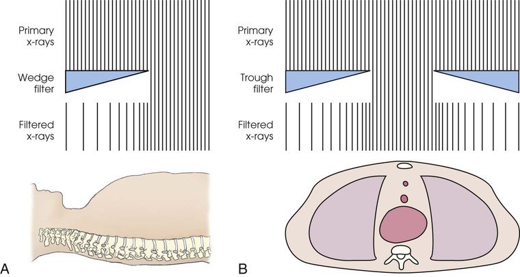
The wedge is the simplest and most common of the compensating filter shapes. It is used to improve the image quality of a wide variety of body parts. Various filters with more complex shapes, including the trough, scoliosis, Ferlic,1 and Boomerang, have been developed for technically challenging anatomic areas.2
Some filters have multiple uses. A filter that is shaped for one area of the body can be adapted for other body structures. Filters such as the Ferlic cervicothoracic lateral projection (swimmer's technique) filter can be adapted for the axiolateral projection (Danelius-Miller technique) of the hip with excellent results.
Composition
Compensating filters are composed of a substance of sufficiently high atomic number to attenuate the x-ray beam. The most common filter materials are aluminum and high-density plastics. These are manufactured with varying thickness of material and are generally distributed in a smoothly graduated way that corresponds with the distribution of the different tissue densities of the anatomy (see Fig. 2-2). Aluminum is an efficient attenuator and a common filter material.
Some manufacturers offer compensating filters made from clear leaded plastic, known as Clear Pb,1 which allows the field light to shine through to the patient but still attenuates the x-ray beam (Fig. 2-3, A). This leaded plastic is inappropriate for all filter uses, however, such as in the extremely dense area of the shoulder during lateral spine radiography, because the thickness required to attenuate the beam sufficiently would result in a prohibitively heavy device. In these cases, aluminum is generally used. The Boomerang (Fig. 2-3, C) filter is composed of an attenuating silicon rubber compound, and some models of this filter have an embedded metal bead chain to mark the filter edge.
Placement
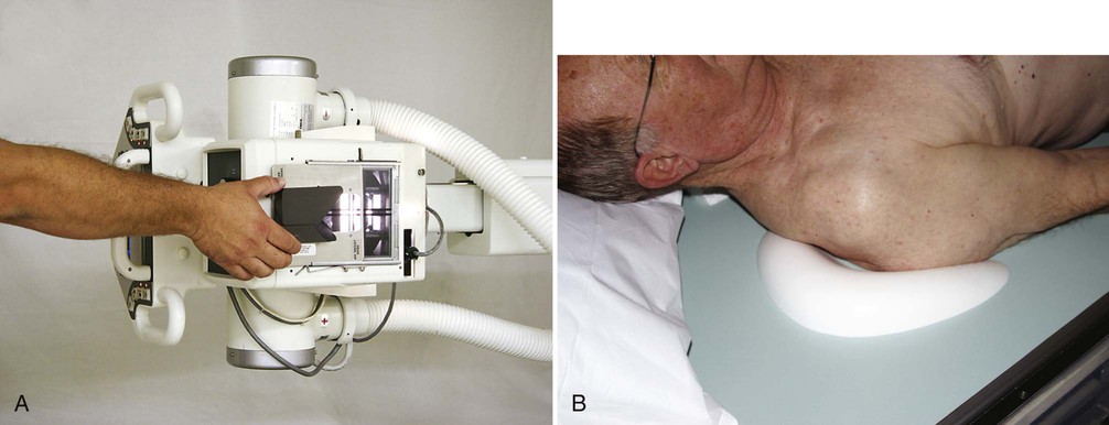
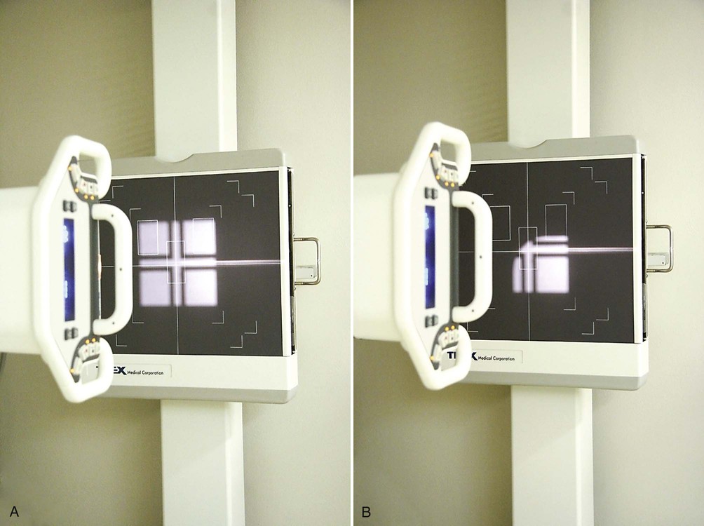
Compensating filters are most often placed in the x-ray beam between the x-ray tube and the patient. Broadly, filters fall into two categories based on their location during use: collimator-mounted filters and contact filters. Collimator-mounted filters are mounted on the collimator, using rails installed on both sides of the window on the collimator housing (Fig. 2-4, A) or magnets. Contact compensating filters may be placed directly on the patient or between the anatomy and the IR (Fig. 2-4, B).
Collimator-mounted filters made of aluminum block the field light, which makes positioning of the patient and the central ray more challenging. Many aluminum filters have a 100% x-ray transmission zone (see Fig. 2-3, B, D, E, and F), which makes positioning slightly easier. Radiographers who use aluminum filters must complete positioning of the patient and alignment of the central ray first, before mounting the filter to the collimator (Fig. 2-5).
Generally, filters placed between the primary beam and the body provide the added benefit of a reduction in radiation exposure to the patient because of the beam-hardening effect of the filter, whereas filters placed between the anatomy and the IR have no effect on patient exposure. Measurements provided with Ferlic filters show radiation exposure reductions of 50% to 80%, depending on the kilovoltage peak (kVp), in the anatomic area covered by the filter. Measurements by Frank et al.1 show exposure reductions of 20% to 69% to the thyroid, sternum, and breasts. Both types have the same effect on the finished image, which is an appropriate brightness range even though the tissue density varies greatly. Filters can be improvised as well, with radiographers creating their own version of attenuation control devices, such as filled bags of saline solution. However, bags of solution increase scattered radiation. Use of improvised filters is not recommended because of the potential for creating unknown artifacts in the image.
Specific Applications
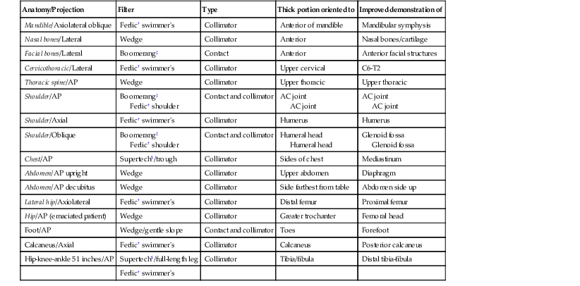
The choice of compensating filter to be used depends on the distribution of tissue densities of the anatomy to be radiographed. As illustrated in Table 2-1, most of these imaging challenges can be solved with only a few filter shapes. The following are examples of the most common compensating filter applications.
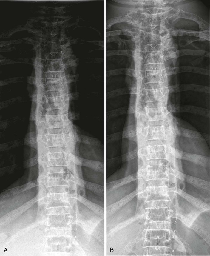
• The wedge filter is used for areas of the body where tissue density varies gradually from one end to the other along the long axis of the body. The wedge filter can be used to improve image quality of AP projections of the thoracic spine (Fig. 2-6).
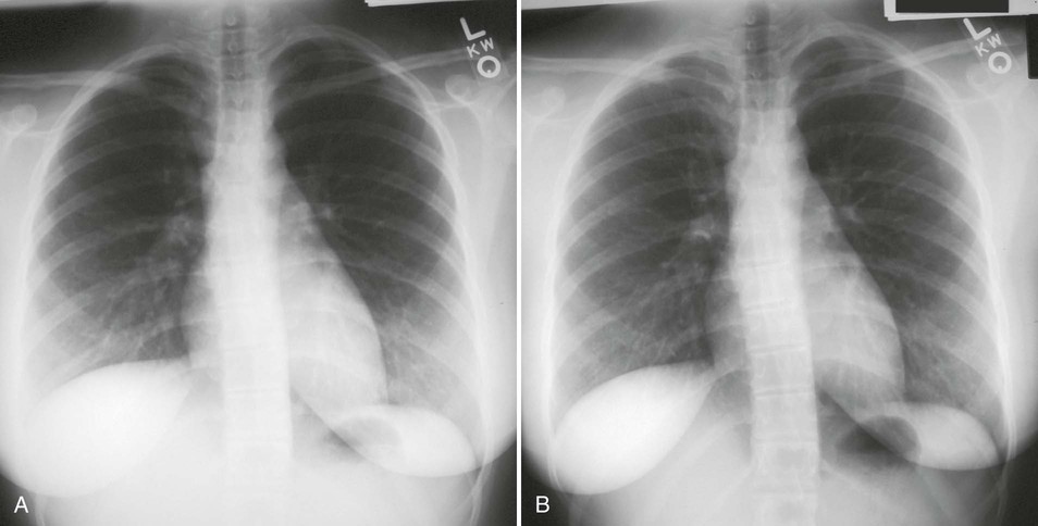
• The trough filter is best used for areas of the body where the subject density in the center is much greater than at the edges. This filter has been successfully applied to improving PA projections of the chest (Fig. 2-7).
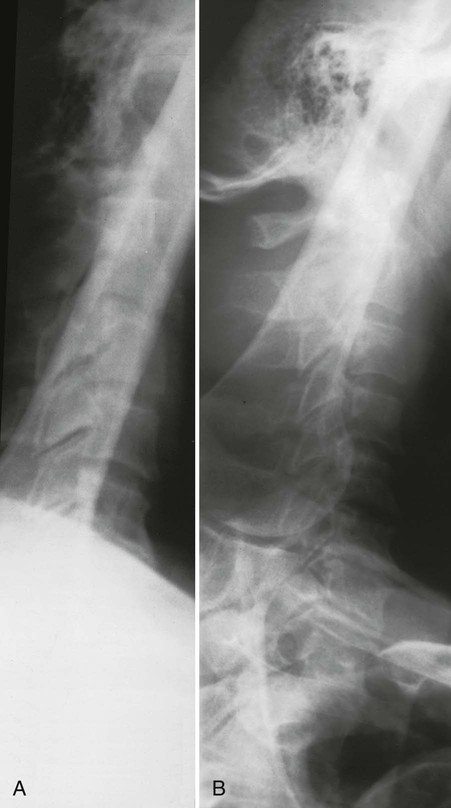
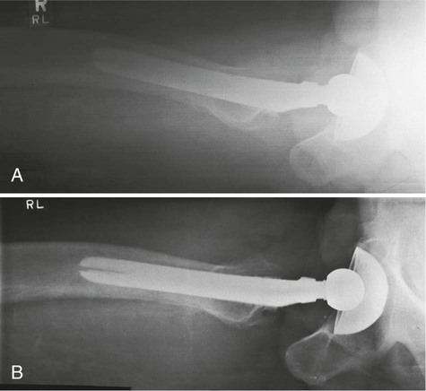
• The Ferlic swimmer's filter is a collimator-mounted filter created to improve imaging of the lateral projection of the cervicothoracic region (swimmer's technique) (Fig. 2-8), but it is also used for the axiolateral projection of the hip (Danelius-Miller method) (Fig. 2-9). The Ferlic shoulder filter, also a collimator-mounted filter, is designed specifically to image the shoulder in both supine and upright positions.
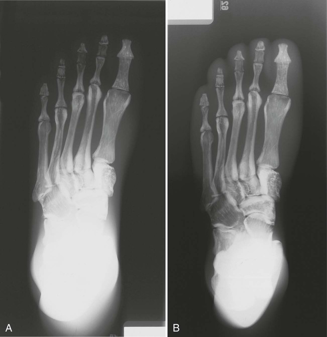
• Specialized wedge filters are designed for specific uses. Fig. 2-10 shows the results of using the Ferlic foot filter to provide a significantly improved image of the foot with one exposure.
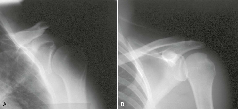
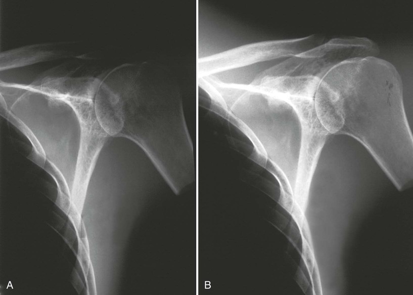
• The Boomerang filter was designed to conform to the shape of the shoulder and to create images of more uniform radiographic density at the superior margins (Fig. 2-11). This is a contact filter placed between the anatomy and the IR (see Fig. 2-4, B). It can also be used effectively for lateral facial bone images. Although effective in compensating for differences in anatomic density, this filter does not reduce radiation exposure because it is located behind the patient. The Ferlic shoulder filter is a collimator-mounted filter also designed specifically to image the shoulder (Fig. 2-12). Because this filter is placed in the primary x-ray beam, it acts to reduce radiation exposure to the patient.
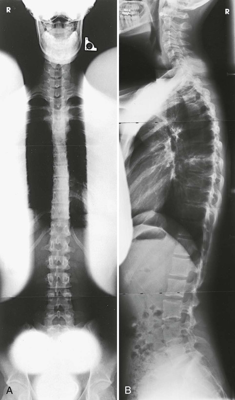
• The scoliosis filters are used with two of the most challenging projections to obtain: PA (Frank et al. method) and lateral full-spine projections for evaluation of spinal curvatures. These projections are challenging because the cervical, thoracic, and lumbosacral spines have to be shown on one image. One exposure technique has to be set for what normally would be three separate exposures. With the use of compensating filters, the PA projection can be made with a wedge filter positioned over the cervical and thoracic spines (Fig. 2-13, A). For the lateral projection, two double-wedge filters are positioned over the midthoracic area and the cervical spine (Fig. 2-13, B). The exposure technique for PA and lateral projections is set to penetrate the most dense area—the lumbar spine. The filters attenuate enough of the exposure over the cervical and thoracic areas to show the thoracic and cervical spines adequately.
TABLE 2-1
Common x-ray projections for which filters improve image quality*
| Anatomy/Projection | Filter | Type | Thick portion oriented to | Improved demonstration of |
| Mandible/Axiolateral oblique | Ferlic† swimmer's | Collimator | Anterior of mandible | Mandibular symphysis |
| Nasal bones/Lateral | Wedge | Collimator | Anterior | Nasal bones/cartilage |
| Facial bones/Lateral | Boomerang‡ | Contact | Anterior | Anterior facial structures |
| Cervicothoracic/Lateral | Ferlic† swimmer's | Collimator | Upper cervical | C6-T2 |
| Thoracic spine/AP | Wedge | Collimator | Upper thoracic | Upper thoracic |
| Shoulder/AP | Boomerang‡ Ferlic† shoulder | Contact and collimator | AC joint AC joint | AC joint AC joint |
| Shoulder/Axial | Ferlic† swimmer's | Collimator | Humerus | Humerus |
| Shoulder/Oblique | Boomerang‡ Ferlic† shoulder | Contact and collimator | Humeral head Humeral head | Glenoid fossa Glenoid fossa |
| Chest/AP | Supertech§/trough | Collimator | Sides of chest | Mediastinum |
| Abdomen/AP upright | Wedge | Collimator | Upper abdomen | Diaphragm |
| Abdomen/AP decubitus | Wedge | Collimator | Side farthest from table | Abdomen side up |
| Lateral hip/Axiolateral | Ferlic† swimmer's | Collimator | Distal femur | Proximal femur |
| Hip/AP (emaciated patient) | Wedge | Collimator | Greater trochanter | Femoral head |
| Foot/AP | Wedge/gentle slope | Contact and collimator | Toes | Forefoot |
| Calcaneus/Axial | Ferlic† swimmer's | Collimator | Calcaneus | Posterior calcaneus |
| Hip-knee-ankle 51 inches/AP | Supertech§/full-length leg | Collimator | Tibia/fibula | Distal tibia-fibula |
| Ferlic† swimmer's |
Highly specialized compensating filters are also used in other areas of the radiology department. During digital fluoroscopy, convex and concave conical-shaped filters are used to compensate for the round image intensifier. In computed tomography (CT), “bow-tie”–shaped filters are used to compensate for the rounded shape of the head.
Radiographers must use caution when mounting and removing compensating filters on the collimator while the x-ray tube is over the patient. There have been instances when filters did not attach properly, did not get positioned into the filter track, or were forgotten and fell onto the patient when the tube was moved. All compensating filters, especially aluminum ones, are moderately heavy with sharp edges; they can cause injury to the patient if dropped. When positioning the filter to the underside of the collimator, and when removing it, two hands must be used (Fig. 2-14). One hand should attach the filter while the other is positioned to catch the filter if it does not attach properly.

Compensating Filters in This Atlas
Body structures whose radiographic images can be improved through the use of compensating filters are identified throughout the atlas directly on the projection page. The special icon  identifies the use of a filter.