Position of part
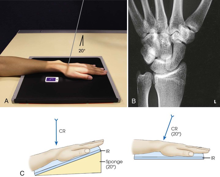
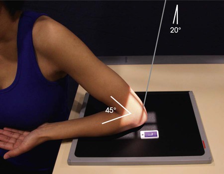
• Place one end of the IR on a support, and adjust the IR so that the finger end of the IR is elevated 20 degrees (Fig. 4-87).
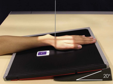
• Adjust the wrist on the IR for a PA projection, and center the wrist to the IR.
• Bridgman2 suggested positioning the wrist in ulnar deviation for this radiograph.
Structures shown
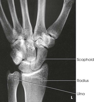
The 20-degree angulation of the wrist places the scaphoid at right angles to the central ray, so that it is projected with minimal superimposition (Figs. 4-88 and 4-89).

Variations
Stecher1 recommended the previous method as preferable; however, a similar position can be obtained by placing the IR and wrist horizontally and directing the central ray 20 degrees toward the elbow (Fig. 4-90).
To show a fracture line that angles superoinferiorly, these positions may be reversed. In other words, the wrist may be angled inferiorly, or from the horizontal position the central ray may be angled toward the digits.
A third method recommended by Stecher is to have the patient clench the fist. This elevates the distal end of the scaphoid so that it lies parallel with the IR; it also widens the fracture line. The wrist is positioned as for the PA projection, and no central ray angulation is used.
Scaphoid Series
PA and PA Axial Projections
RAFERT-LONG METHOD
Ulnar deviation
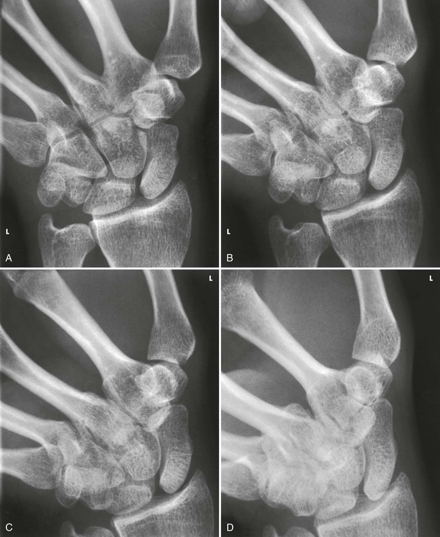
Scaphoid fractures account for 60% of all carpal bone injuries. In 1991, Rafert and Long1 described this method of diagnosing scaphoid fractures using a four-image, multiple-angle central ray series. The series is performed after routine wrist radiographs do not identify a fracture, but symptoms are suspicious for scaphoid fracture.
Image receptor: 8 × 10 inch (18 × 24 cm) or 10 × 12 inch (24 × 30 cm) lengthwise, depending on availability; crosswise for multiple images
Position of part
• Position the wrist on the IR for a PA projection.
• Without moving the forearm, turn the hand outward until the wrist is in extreme ulnar deviation (Fig. 4-91).

Structures shown
The scaphoid is shown with minimal superimposition (Fig. 4-92).
Trapezium
PA Axial Oblique Projection
Clements-Nakayama Method
Fractures of the trapezium are rare; however, if undiagnosed, these fractures can lead to functional difficulties. In certain cases, the articular surfaces of the trapezium should be evaluated to treat patients with osteoarthritis.1
Image receptor: 8 × 10 inch (18 × 24 cm) or 10 × 12 inch (24 × 30 cm) lengthwise, depending on availability
Position of part
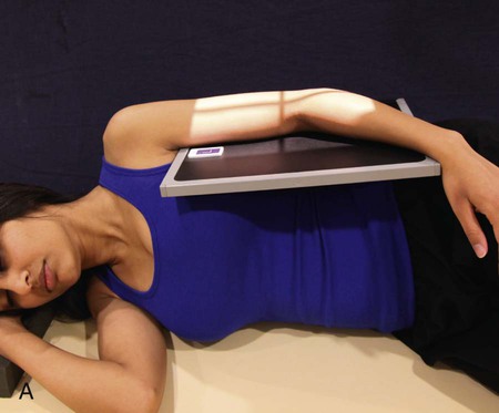
• Place the wrist in the lateral position, resting on the ulnar surface over the center of the IR.
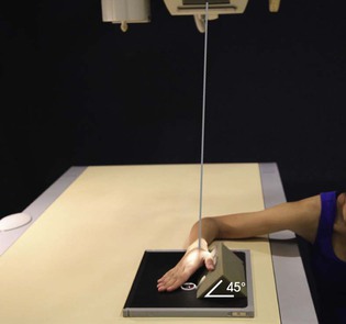
• Place a 45-degree sponge wedge against the anterior surface, and rotate the hand to come in contact with the sponge.
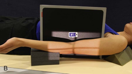
• If the patient is able to achieve ulnar deviation, adjust the IR so that the long axis of the IR and the forearm align with the central ray (Fig. 4-93).
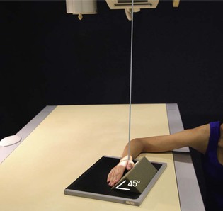
• If the patient is unable to achieve ulnar deviation comfortably, align the straight wrist to the IR, and rotate the elbow end of the IR and arm 20 degrees away from the central ray (Fig. 4-94).
Structures shown
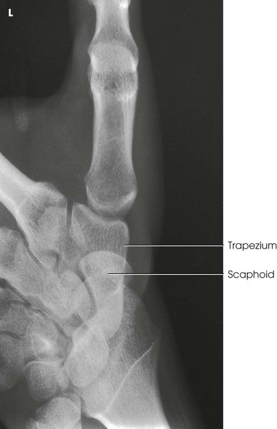
The image clearly shows the trapezium and its articulations with adjacent carpal bones (Fig. 4-95). The articulation of the trapezium and scaphoid is not shown on this image.
Carpal Bridge
Tangential Projection
Image receptor: 8 × 10 inch (18 × 24 cm) or 10 × 12 inch (24 × 30 cm) lengthwise, depending on availability
Position of part
• The originators1 of this projection recommended that the hand lie palm upward on the IR with the hand at right angle to the forearm (Fig. 4-96).

• When the wrist is too painful to be adjusted in the position just described, a similar image can be obtained by elevating the forearm on sandbags or other suitable support. Then with the wrist flexed in right-angle position, place the IR in the vertical position (Fig. 4-97).

 inches (3.8 cm) proximal to the wrist joint at a caudal angle of 45 degrees
Structures shown
The carpal bridge is shown on the image in Figs. 4-98 and 4-99. The originators recommended this procedure to show fractures of the scaphoid, lunate dislocations, calcifications and foreign bodies in the dorsum of the wrist, and chip fractures of the dorsal aspect of the carpal bones.
Carpal Canal
 Tangential Projections
Gaynor-Hart Method1
The carpal canal contains the tendons of the flexors of the fingers and the median nerve. Compression of the median nerve results in pain. Radiography is performed to identify abnormality of the bones or soft tissue of the canal.
Fractures of the hook of hamate, pisiform, and trapezium are increasingly seen in athletes. The tangential projection is helpful in identifying fractures of these carpal bones. This projection was added as an essential projection based on the 1997 survey performed by Bontrager.2
Image receptor: 8 × 10 inch (18 × 24 cm) or 10 × 12 inch (24 × 30 cm) lengthwise, depending on availability
Inferosuperior
Position of patient
• Seat the patient at the end of the radiographic table so that the forearm can be adjusted to lie parallel with the long axis of the table.
Position of part
• Hyperextend the wrist, and center the IR to the joint at the level of the radial styloid process.
• For support, place a radiolucent pad approximately  inch (1.9 cm) thick under the lower forearm.
• Adjust the position of the hand to make its long axis as vertical as possible.
• To prevent superimposition of the shadows of the hamate and pisiform bones, rotate the hand slightly toward the radial side.
• Have the patient grasp the digits with the opposite hand, or use a suitable device to hold the wrist in the extended position (Fig. 4-100).
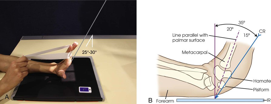
Central ray
• Directed to the palm of the hand at a point approximately 1 inch (2.5 cm) distal to the base of the third metacarpal and at an angle of 25 to 30 degrees to the long axis of the hand
• When the wrist cannot be extended to within 15 degrees of vertical, McQuillen Martensen1 suggested that the central ray first be aligned parallel to the palmar surface, then angled an additional 15 degrees toward the palm.
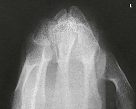
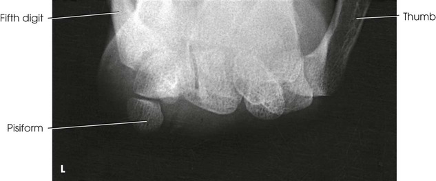
Structures shown
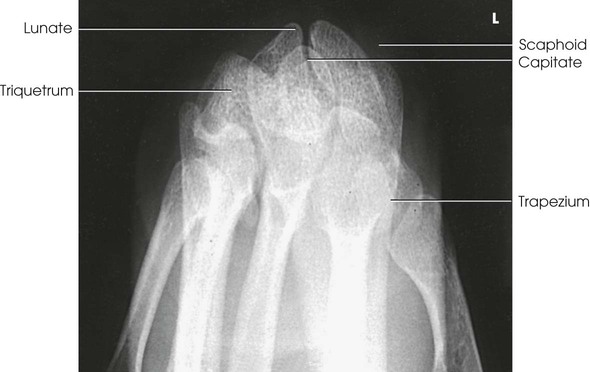
This image of the carpal canal (carpal tunnel) shows the palmar aspect of the trapezium; the tubercle of the trapezium; and the scaphoid, capitate, hook of hamate, triquetrum, and entire pisiform (Fig. 4-101).

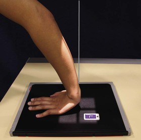
Superoinferior
Position of patient
• When the patient cannot assume or maintain the previously described wrist position, a similar image may be obtained.
• Have the patient dorsiflex the wrist as much as is tolerable and lean forward to place the carpal canal tangent to the IR (Fig. 4-102). The canal is easily palpable on the palmar aspect of the wrist as the concavity between the trapezium laterally and hook of hamate and pisiform medially.
Position of part
• When dorsiflexion of the wrist is limited, Marshall1 suggested placing a 45-degree angle sponge under the palmar surface of the hand. The sponge slightly elevates the wrist to place the carpal canal tangent to the central ray. A slight degree of magnification exists because of the increased object-to-IR distance (OID) (Fig. 4-103).
Forearm
AP Projection
The IR should be long enough to include the entire forearm from the olecranon process of the ulna to the styloid process of the radius and the wrist and elbow joints. Both images of the forearm may be taken on one CR IP or screen-film cassette by alternately covering one half of the IR with a lead mask. If a screen-film cassette is used, space should be allowed for the patient identification marker so that no part of the radiographic image is cut off.
Image receptor: 11 × 14 inch (30 × 35 cm) or14 × 17 inch (35 × 43 cm) lengthwise, depending on availability
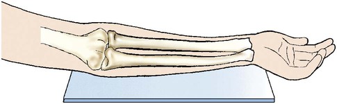
Position of part
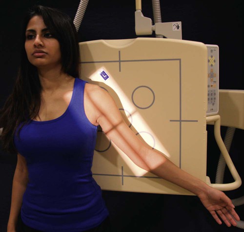
• Supinate the hand, extend the elbow, and place the dorsal surface of the forearm against the IR. Ensure that the joint of interest is included.
• Adjust the IR so that the long axis is parallel with the forearm.
• Have the patient lean laterally until the forearm is in a true supinated position (Fig. 4-104).
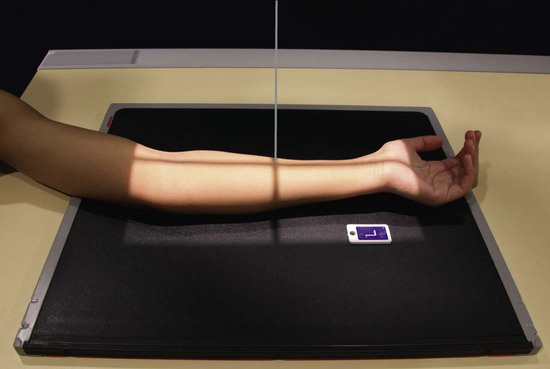
• Because the proximal forearm is commonly rotated in this position, palpate and adjust the humeral epicondyles to be equidistant from the IR.
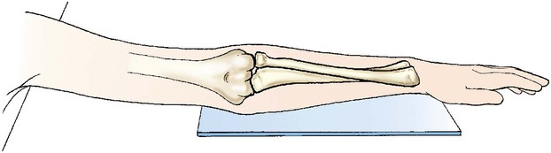
• Ensure that the hand is supinated (Fig. 4-105). Pronation of the hand crosses the radius over the ulna at its proximal third and rotates the humerus medially, resulting in an oblique projection of the forearm (Fig. 4-106).
Computed Radiography
The forearm must be centered to the plate or plate section with four collimator margins or with no margins at all. Two images can be projected on one plate; however, because the arm takes up most of the plate half, collimate to the margins of the plate. A lead blocker must cover the opposite side when two images are made on one IR.
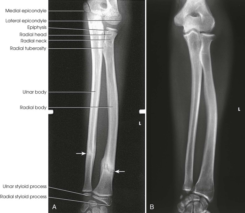
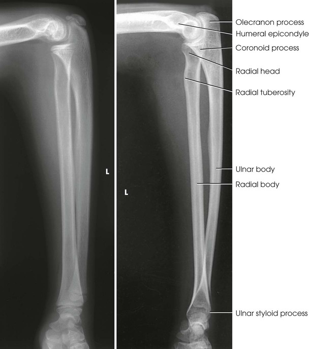
Structures shown
An AP projection of the forearm shows the elbow joint, the radius and ulna, and the proximal row of slightly distorted carpal bones (Fig. 4-107).
Lateral Projection
Lateromedial
Image receptor: 11 × 14 inch (30 × 35 cm) or 14 × 17 inch (35 × 43 cm) lengthwise, depending on availability
Position of part
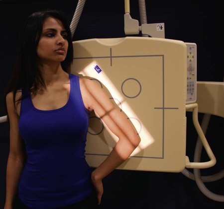
• Flex the elbow 90 degrees, and place the medial aspect of the forearm against the IR. Ensure that the entire joint of interest is included.
• Adjust the IR so that the long axis is parallel with the forearm.
• Adjust the limb in a true lateral position. The thumb side of the hand must be up (Fig. 4-108).

Structures shown
The lateral projection shows the bones of the forearm, the elbow joint, and the proximal row of carpal bones (Fig. 4-109).
Elbow
AP Projection
Image receptor: 8 × 10 inch (18 × 24 cm) or 10 × 12 inch (24 × 30 cm) lengthwise, depending on availability
Position of part
• Extend the elbow, supinate the hand, and center the IR to the elbow joint.
• Adjust the IR to make it parallel with the long axis of the part (Fig. 4-110).

• Have the patient lean laterally until the humeral epicondyles and anterior surface of the elbow are parallel with the plane of the IR.
• Supinate the hand to prevent rotation of the bones of the forearm.
Computed Radiography
The elbow must be centered to the plate or plate section with four collimator margins or with no margins at all. Two images can be projected on one plate; however, because the elbow projection takes up most of the plate half, collimate to the margins of the plate. A lead blocker must cover the opposite side when two images are made on one IR.
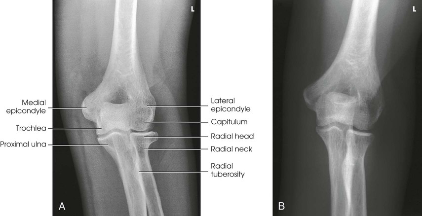
Structures shown
An AP projection of the elbow joint, distal arm, and proximal forearm is presented (Fig. 4-111).
Lateral Projection
Lateromedial
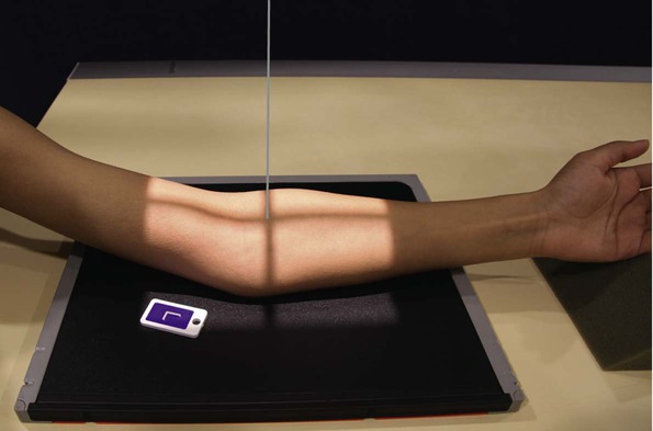
Griswold1 gave two reasons for the importance of flexing the elbow 90 degrees: (1) The olecranon process can be seen in profile, and (2) the elbow fat pads are the least compressed. In partial or complete extension, the olecranon process elevates the posterior elbow fat pad and simulates joint pathology.
Image receptor: 8 × 10 inch (18 × 24 cm) or 10 × 12 inch (24 × 30 cm) lengthwise, depending on availability
Position of part
• From the supine position, flex the elbow 90 degrees, and place the humerus and forearm in contact with the table.
• Center the IR to the elbow joint. Adjust the elbow joint so that its long axis is parallel with the long axis of the forearm (Figs. 4-112 and 4-113). On patients with muscular forearms, elevate the wrist to place the forearm parallel with the IR.


• Adjust the IR diagonally to include more of the arm and forearm (Fig. 4-114).

• To obtain a lateral projection of the elbow, adjust the hand in the lateral position and ensure that the humeral epicondyles are perpendicular to the plane of the IR.
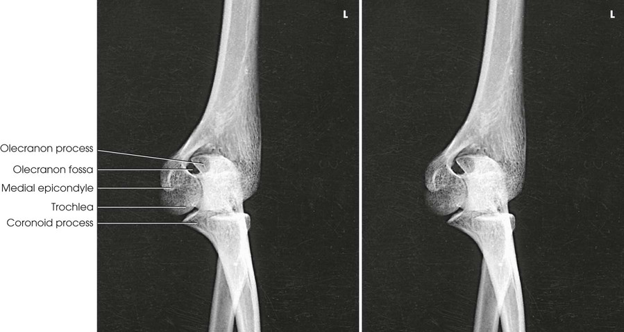
Structures shown
The lateral projection shows the elbow joint, distal arm, and proximal forearm (see Figs. 4-113 and 4-114).
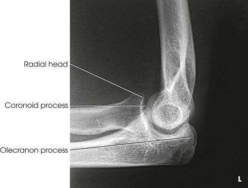
Evaluation Criteria
The following should be clearly shown:
▪ Evidence of proper collimation
▪ Elbow joint open and centered to the central ray
▪ Elbow in a true lateral position:
□ Superimposed humeral epicondyles
□ Radial tuberosity facing anteriorly
□ Radial head partially superimposing the coronoid process
□ Olecranon process in profile
▪ Bony trabecular detail and any elevated fat pads in the soft tissue at the anterior and posterior distal humerus and the anterior proximal forearm
NOTE: When injury to the soft tissue around the elbow is suspected, the joint should be flexed only 30 or 35 degrees (Fig. 4-115). This partial flexion does not compress or stretch the soft structures as does the full 90-degree lateral flexion. The posterior fat pad may become visible in this position.

AP Oblique Projection
Medial rotation
Image receptor: 8 × 10 inch (18 × 24 cm) or 10 × 12 inch (24 × 30 cm) lengthwise, depending on availability
Position of part
• Extend the limb in position for an AP projection, and center the midpoint of the IR to the elbow joint (Fig. 4-116).
• Medially (internally) rotate or pronate the hand, and adjust the elbow to place its anterior surface at an angle of 45 degrees. This degree of obliquity usually clears the coronoid process of the radial head.
Structures shown
The image shows an oblique projection of the elbow with the coronoid process projected free of superimposition (Fig. 4-117).
AP Oblique Projection
Lateral rotation
Image receptor: 8 × 10 inch (18 × 24 cm) or 10 × 12 inch (24 × 30 cm) lengthwise, depending on availability
Position of part
• Extend the patient's arm in position for an AP projection, and center the midpoint of the IR to the elbow joint.
• Rotate the hand laterally (externally) to place the posterior surface of the elbow at a 45-degree angle (Fig. 4-118). When proper lateral rotation is achieved, the patient's first and second digits should touch the table.
Structures shown
The image shows an oblique projection of the elbow with the radial head and neck projected free of superimposition of the ulna (Fig. 4-119).
Distal Humerus
AP Projection
Partial flexion
When the patient cannot completely extend the elbow, the lateral position is easily performed; however, two AP projections must be obtained to avoid distortion. Separate AP projections of the distal humerus and proximal forearm are required.
Image receptor: 8 × 10 inch (18 × 24 cm) or 10 × 12 inch (24 × 30 cm) lengthwise, depending on availability
Position of part
• If possible, supinate the hand. Place the IR under the elbow, and center it to the condyloid area of the humerus (Fig. 4-120).
Structures shown
This projection shows the distal humerus when the elbow cannot be fully extended (Figs. 4-121 and 4-122).


Proximal Forearm
AP Projection
Partial flexion
Image receptor: 8 × 10 inch (18 × 24 cm) or 10 × 12 inch (24 × 30 cm) lengthwise, depending on availability
Position of part
• Seat the patient high enough to permit the dorsal surface of the forearm to rest on the table (Fig. 4-123). If this position is impossible, elevate the limb on a support, adjust the limb in the lateral position, place the IR in the vertical position behind the upper end of the forearm, and direct the central ray horizontally.

Structures shown
This projection shows the proximal forearm when the elbow cannot be fully extended (Figs. 4-124 and 4-125).
Distal Humerus
AP Projection
Acute flexion
When fractures around the elbow are being treated using the Jones orthopedic technique (complete flexion), the lateral position offers little difficulty, but the frontal projection must be made through the superimposed bones of the AP arm and PA forearm. This projection is sometimes known as the Jones method, although no “Jones” reference has been found.
Image receptor: 8 × 10 inch (18 × 24 cm) or 10 × 12 inch (24 × 30 cm) lengthwise, depending on availability
Position of part
• Center the IR proximal to the epicondylar area of the humerus. The long axis of the arm and forearm should be parallel with the long axis of the IR (Figs. 4-126 and 4-127).

• Adjust the arm or the radiographic tube and IR to prevent rotation.
Structures shown
This position superimposes the bones of the forearm and arm. The olecranon process should be clearly shown (Fig. 4-128).
Proximal Forearm
PA Projection
Acute flexion
Image receptor: 8 × 10 inch (18 × 24 cm) or 10 × 12 inch (24 × 30 cm) lengthwise, depending on availability
Position of part
• Center the flexed elbow joint to the center of the IR. The long axis of the superimposed forearm and arm should be parallel with the long axis of the IR (Figs. 4-129 and 4-130).

• Move the IR toward the shoulder so that the central ray passes to the midpoint.
Structures shown
The superimposed bones of the arm and forearm are outlined (Fig. 4-131). The elbow joint should be more open than for projections of the distal humerus.

Radial Head
Lateral Projection
Lateromedial
Place the IR in position, and cover the unused section with a sheet of lead. To show the entire circumference of the radial head free of superimposition, four projections with varying positions of the hand are performed.
Image receptor: 8 × 10 inch (18 × 24 cm) or 10 × 12 inch (24 × 30 cm), depending on availability
Position of part
• Flex the elbow 90 degrees, center the joint to the unmasked IR, and place the joint in the lateral position.
• Make the first exposure with the hand supinated as much as is possible (Fig. 4-132).

• Shift the IR and make the second exposure with the hand in the lateral position, that is, with the thumb surface up (Fig. 4-133).
• Shift the IR, then make the third exposure with the hand pronated (Fig. 4-134).

• Shift the IR, and make the fourth exposure with the hand in extreme internal rotation, that is, resting on the thumb surface (Fig. 4-135).

Structures shown
The radial head is projected in varying degrees of rotation (Figs. 4-136 through 4-139).
Radial Head and Coronoid Process
Axiolateral Projection
COYLE METHOD
Lateral
NOTE: This projection was devised for obtaining images of the radial head and coronoid process on patients who cannot fully extend the elbow for medial and lateral oblique projections.1 It is particularly useful in imaging a traumatized elbow.
Image receptor: 8 × 10 inch (18 × 24 cm) or 10 × 12 inch (24 × 30 cm) lengthwise, depending on availability
Position of part
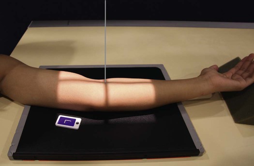
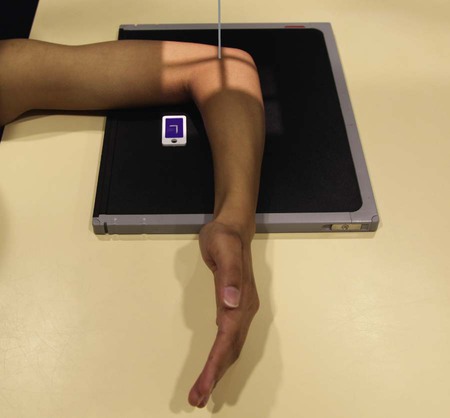
• Seat the patient at the end of the radiographic table low enough to place the humerus, elbow, and wrist joints on the same plane.
• Pronate the hand and flex the elbow 90 degrees to show the radial head or 80 degrees to show the coronoid process.
• Center the IR to the elbow joint. For patients with muscular forearms, elevate the wrist to place the forearm parallel with the IR (Fig. 4-140).

Supine position for trauma
• In most instances of trauma, the patient is lying in the supine position on a cart. The projection is easily performed in this position.
• Elevate the distal humerus on a radiolucent sponge.
• Place the IR in vertical position centered to the elbow joint.
• Epicondyles should be approximately perpendicular to the IR.
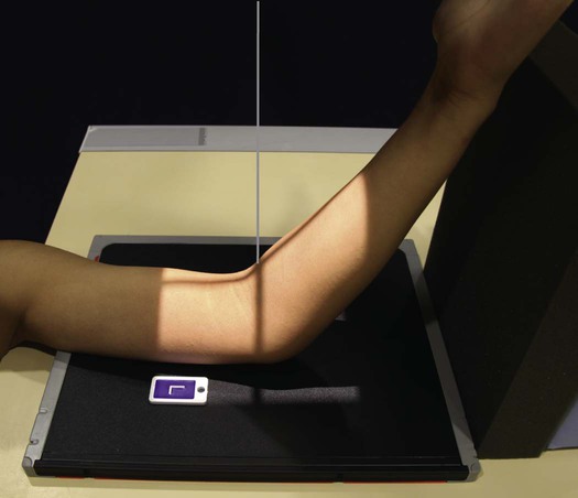
• Slowly flex the elbow 90 degrees to show the radial head or 80 degrees for the coronoid process. Turn the hand so that the palmar aspect is facing medially. An assistant may need to hold the hand depending on the severity of trauma (Fig. 4-141).
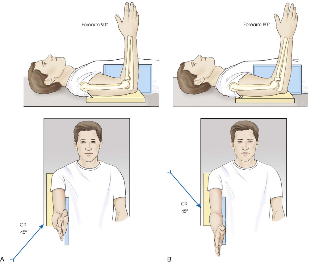
Central ray
• Directed toward the shoulder at an angle of 45 degrees to the radial head; central ray enters the joint at mid-elbow (see Fig. 4-140, A)
Coronoid process
• Directed away from the shoulder at an angle of 45 degrees to the coronoid process; central ray enters the joint at mid-elbow (see Fig. 4-140, B)
Supine position for trauma
• The horizontal central ray is directed cephalad at an angle of 45 degrees to the radial head, entering the joint at mid-elbow (see Fig. 4-141, A).
Coronoid process
• The horizontal central ray is directed caudad at an angle of 45 degrees to the coronoid process, entering the joint at mid-elbow (see Fig. 4-141, B).
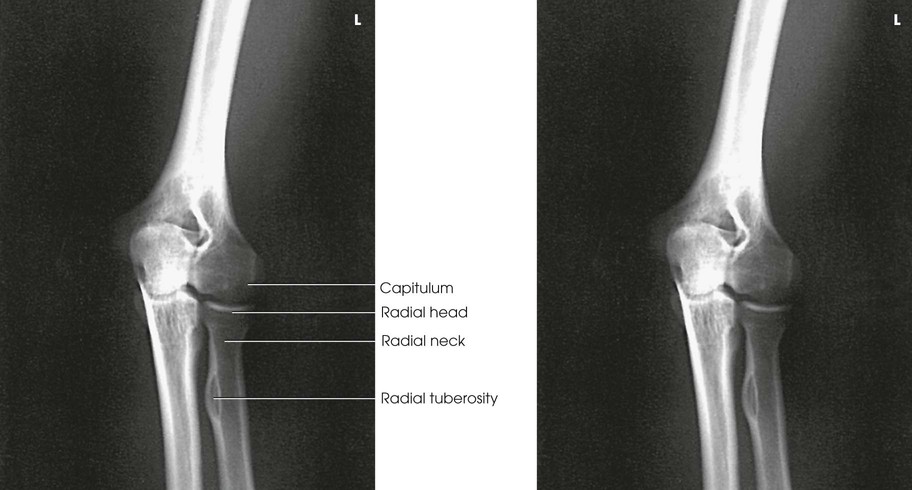
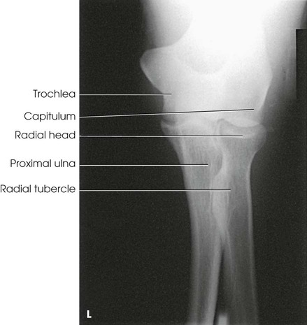
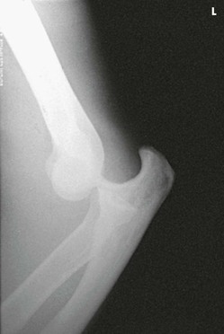
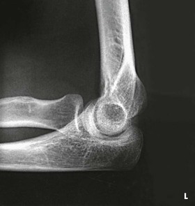
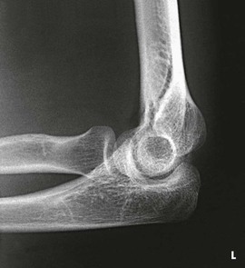
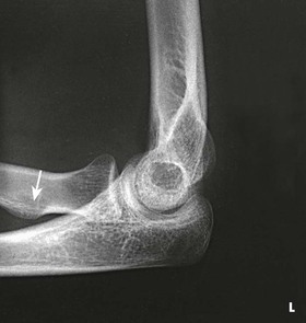
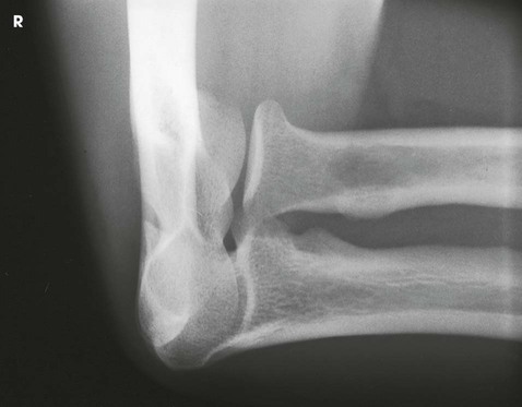
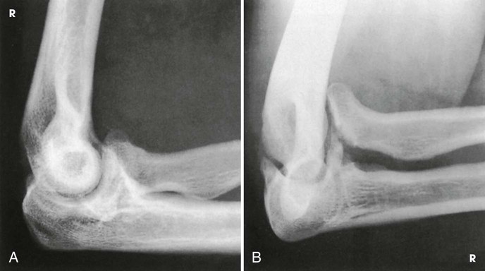
Structures shown
The resulting projections show an open elbow joint between the radial head and capitulum (Fig. 4-142) or between the coronoid process and trochlea (Fig. 4-143) with the area of interest in profile. These projections are used to show pathologic processes or trauma in the area of the radial head and coronoid process. The value of the projections is evident in the trauma images shown in Fig. 4-144.1

Distal Humerus
PA Axial Projection
Image receptor: 8 × 10 inch (18 × 24 cm) or 10 × 12 inch (24 × 30 cm) lengthwise, depending on availability
Position of part
• Ask the patient to rest the forearm on the table, and then adjust the forearm so that its long axis is parallel with the table.
• Center a point midway between the epicondyles and the center of the IR.
• Flex the patient's elbow to place the arm in a nearly vertical position so that the humerus forms an angle of approximately 75 degrees from the forearm (approximately 15 degrees between the central ray and the long axis of the humerus).
• Confirm that the patient is not leaning anteriorly or posteriorly.
• Supinate the hand to prevent rotation of the humerus and ulna, and have the patient immobilize it with the opposite hand (Fig. 4-145).

Structures shown
This projection shows the epicondyles, trochlea, ulnar sulcus (groove between the medial epicondyle and the trochlea), and olecranon fossa (Fig. 4-146). The projection is used in radiohumeral bursitis (tennis elbow) to detect otherwise obscured calcifications located in the ulnar sulcus.

NOTE: Long and Rafert1 describe an AP oblique distal humerus projection that specifically shows the ulnar sulcus.
Olecranon Process
PA Axial Projection
Image receptor: 8 × 10 inch (18 × 24 cm) or 10 × 12 inch (24 × 30 cm) lengthwise, depending on availability
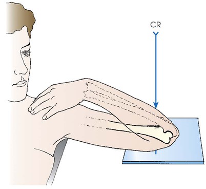
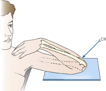
Position of part
Central ray
• Perpendicular to the olecranon process to show the dorsum of the olecranon process and at a 20-degree angle toward the wrist to show the curved extremity and articular margin of the olecranon process (Fig. 4-147)
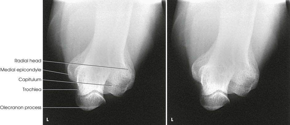
Structures shown
The projection shows the olecranon process and the articular margin of the olecranon and humerus (Figs. 4-148 through 4-150).


Humerus
AP Projection
Upright
Shoulder and arm abnormalities, whether traumatic or pathologic in origin, are extremely painful. For this reason, an upright position, either standing or seated, should be used whenever possible. With rotation of the patient's body as required, the arm can be positioned quickly and accurately with minimal discomfort to the patient.
Image receptor: 14 × 17 inch (35 × 43 cm) lengthwise
Position of patient
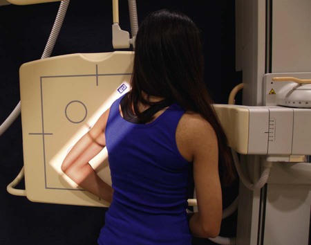
• Place the patient in a seated-upright or standing position facing the x-ray tube.
• Fig. 4-151 illustrates the body position used for an AP projection of a freely movable arm. The body position, whether oblique or facing toward or away from the IR, is unimportant as long as an AP radiograph of the arm is obtained.
Position of part
• Adjust the height of the IR to place its upper margin about  inches (3.8 cm) above the level of the humeral head.
• Abduct the arm slightly, and supinate the hand.
• A coronal plane passing through the epicondyles should be parallel with the IR plane for the AP (or PA) projection (see Fig. 4-151).
Structures shown
The AP projection shows the entire length of the humerus. The accuracy of the position is shown by the epicondyles (Fig. 4-152).

Lateral Projection
Lateromedial, mediolateral
Upright
Image receptor: 14 × 17 inch (35 × 43 cm) lengthwise
Position of part
• Place the top margin of the IR approximately  inches (3.8 cm) above the level of the humeral head.
• Unless contraindicated by possible fracture, internally rotate the arm, flex the elbow approximately 90 degrees, and place the patient's anterior hand on the hip. This places the humerus in lateral position. A coronal plane passing through the epicondyles should be perpendicular with the IR plane (Fig. 4-153).
• A patient with a broken humerus may be easier to position by performing a mediolateral projection as shown in Fig. 4-154. Face the sitting or standing patient toward the IR and incline the thorax as necessary to align the humerus for the mediolateral projection. If the patient is not already holding the hand of the broken arm, have the patient do so.
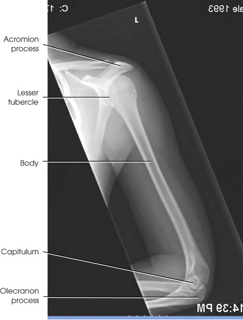
Structures shown
The lateral projection shows the entire length of the humerus. A true lateral image is confirmed by superimposed epicondyles (Fig. 4-155).
AP Projection
Recumbent
The IR size selected should be long enough to include the entire humerus.
Image receptor: 14 × 17 inch (35 × 43 cm) lengthwise
Position of part
• Place the upper margin of the IR approximately  inches (3.8 cm) above the humeral head.
• Elevate the opposite shoulder on a sandbag to place the affected arm in contact with the IR, or elevate the arm and IR on sandbags.
• Unless contraindicated, supinate the hand, extend the elbow, and rotate the limb to place the epicondyles parallel with the plane of the IR (Fig. 4-156).
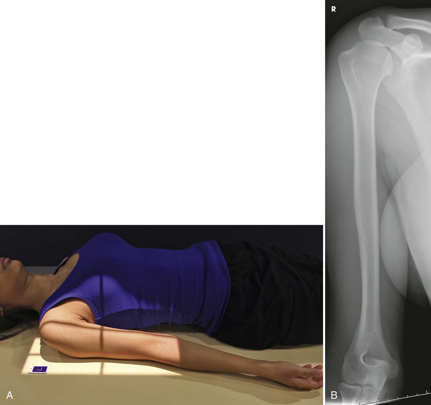
Structures shown
The AP projection shows the entire length of the humerus. The accuracy of the position is shown by the epicondyles (see Fig. 4-156).
Lateral Projection
Lateromedial
Recumbent
Position of part
• Adjust the top of the IR to be approximately  inches (3.8 cm) above the level of the head of the humerus.
• Unless contraindicated by possible fracture, abduct the arm and center the IR under it.
• Rotate the forearm medially to place the epicondyles perpendicular to the plane of the IR, and rest the posterior aspect of the hand against the patient's side. This movement turns the epicondyles in the lateral position without flexing the elbow (see Fig. 4-153). (The elbow may be flexed slightly for comfort.)
• Adjust the position of the IR to include the entire length of the humerus (Fig. 4-157).
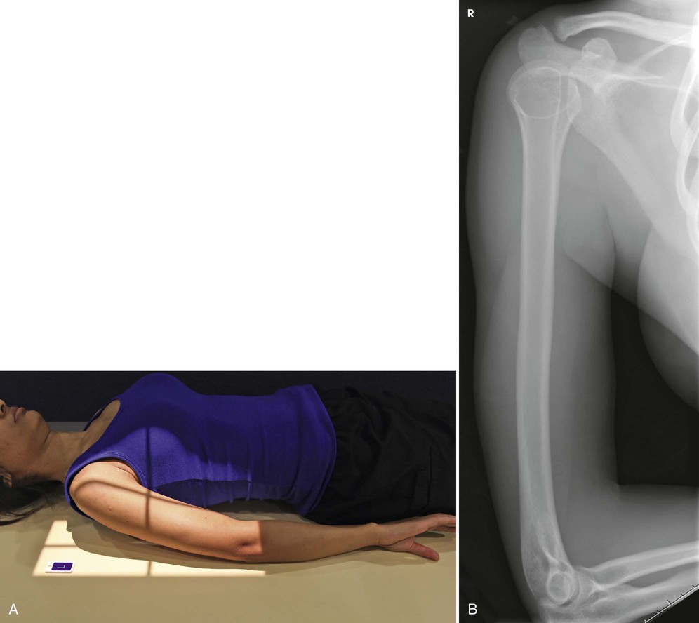
Structures shown
The lateral projection shows the entire length of the humerus. A true lateral image is confirmed by superimposed epicondyles (see Fig. 4-157).
Lateral Projection
Lateromedial
Recumbent or lateral recumbent
Position of patient
• When a known or suspected fracture exists, position the patient in the recumbent or lateral recumbent position, place the IR close to the axilla, and center the humerus to the midline of the IR.
• Unless contraindicated, flex the elbow, turn the thumb surface of the hand up, and rest the humerus on a suitable support (Fig. 4-158).
• Adjust the position of the body to place the lateral surface of the humerus perpendicular to the central ray.
Central ray
Lateral recumbent
• Directed to the center of the IR, which exposes only the distal humerus (see Fig. 4-158)
Structures shown
The lateral projection shows the distal humerus (Fig. 4-159).
