second.
  seconds. Note that lung's vascular markings are blurred.
Thoracic Zygapophyseal Joints
AP or PA Oblique Projection
RAO and LAO or RPO and LPO
Upright and recumbent positions
The thoracic zygapophyseal joints are examined using PA oblique projections as recommended by Oppenheimer1 or using AP oblique projections as recommended by Fuchs.2 The joints are well shown with either projection. AP obliques show the joints farthest from the IR, and PA obliques show the joints closest to the IR. Although the difference in OID between the two projections is not great, the same rotation technique is used bilaterally.
Upright position
Image receptor: 14 × 17 inch (35 × 43 cm)
Position of part
• Rotate the body 20 degrees anterior (PA oblique) or posterior (AP oblique) so that the coronal plane forms an angle of 70 degrees from the plane of the IR.
• Center the patient's vertebral column to the midline of the grid, and have the patient rest the adjacent shoulder firmly against it for support.
• Adjust the height of the IR  to 2 inches (3.8 to 5 cm) above the shoulders to center the IR to T7.
• For the PA oblique, flex the elbow of the arm adjacent to the grid and rest the hand on the hip. For the AP oblique, the arm adjacent to the grid is brought forward to avoid superimposing the humerus on the upper thoracic vertebrae.
• For the PA oblique, have the patient grasp the side of the grid device with the outer hand (Fig. 8-78). For the AP oblique, have the patient place the outer hand on the hip.

• Adjust the patient's shoulders to lie in the same horizontal plane.
• Have the patient stand straight to place the long axis of the vertebral column parallel with the IR.
• The weight of the patient's body must be equally distributed on the feet, and the head must not be turned laterally.
NOTE: See p. 382 for Summary of Oblique Projections.
Recumbent position
Image receptor: 14 × 17 inch (35 × 43 cm)
Position of part
• For anterior (PA oblique) rotation, place the lower arm behind the back and the upper arm forward with the hand on the table for support (Fig. 8-79).

• For posterior (AP oblique) rotation, adjust the lower arm at right angles to the long axis of the body, flex the elbow, and place the hand under or beside the head. Place the upper arm posteriorly and support it (Fig. 8-80).

• Rotate the body slightly, either anteriorly or posteriorly 20 degrees, so that the coronal plane forms an angle of 70 degrees with the horizontal.
• Center the vertebral column to the midline of the grid.
• Center the IR  to 2 inches (3.8 to 5 cm) above the shoulders to center it at the level of T7.
• If needed, apply a compression band across the hips, but be careful not to change the position.
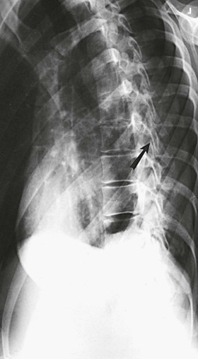
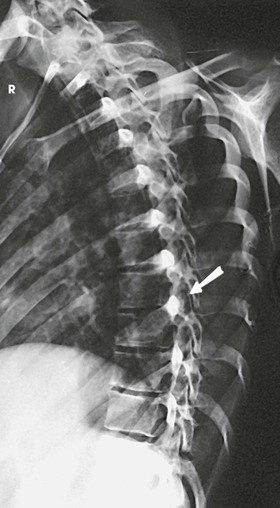
Structures shown
The images show oblique projections of the zygapophyseal joints (arrows on Figs. 8-81 and 8-82). The number of joints shown depends on the thoracic curve. A greater degree of rotation from the lateral position is required to show the joints at the proximal and distal ends of the region in patients with an accentuated dorsal kyphosis. The inferior articular processes of T12, having an inclination of about 45 degrees, are not shown in this projection. (See Summary of Oblique Projections on p. 382.)
Lumbar-Lumbosacral Vertebrae
 AP Projection
PA projection (optional)
If possible, gas and fecal material should be cleared from the intestinal tract for examination of bones lying within the abdominal and pelvic regions. The urinary bladder should be emptied just before the examination to eliminate superimposition caused by the secondary radiation generated within a filled bladder.
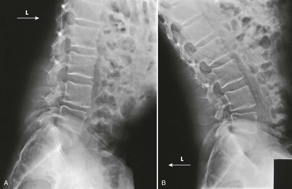
An AP or PA projection may be used, but the AP projection is more commonly employed. The AP projection is generally used for recumbent examinations. The extended limb position accentuates the lordotic curve, resulting in distortion of the bodies and poor delineation of the intervertebral disk spaces (Figs. 8-83 and 8-84). This curve can be reduced by flexing the patient's hips and knees enough to place the back in firm contact with the radiographic table (Figs. 8-85 and 8-86).
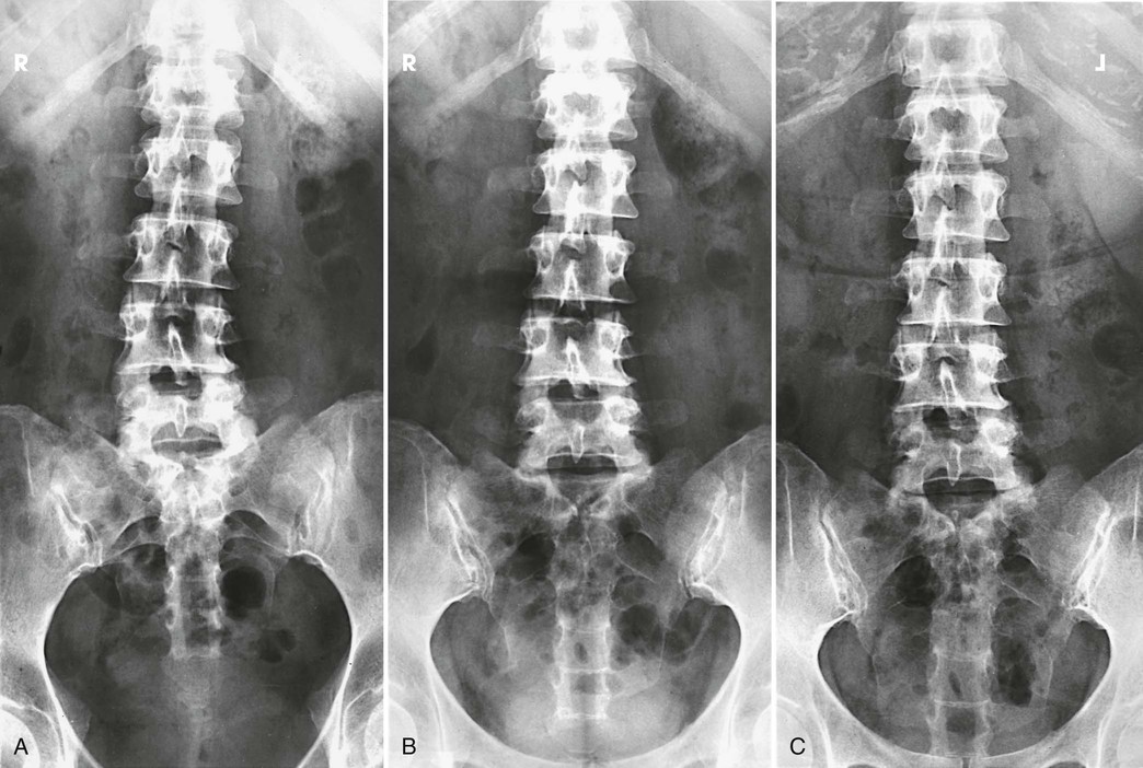


The PA projection places the intervertebral disk spaces at an angle closely paralleling the divergence of the beam of radiation (Fig. 8-87; see Fig. 8-84, C). This projection also reduces the dose to the patient.1 For this reason, the PA projection is sometimes used for upright studies of the lumbar and lumbosacral spine.
Special positioning
• If a patient is having severe back pain, place a footboard on the radiographic table, and stand the table upright before beginning the examination.
• Have the patient stand on the footboard, and position the part for the projection.
• Turn the table to the horizontal position for the exposure, and return it to the upright position for the next projection.
• Although this procedure takes a few minutes, the patient appreciates its ability to minimize the pain.
Image receptor: 11 × 14 inch (30 × 35 cm) or 14 × 17 inch (35 × 43 cm), depending on availability
SID: 48 inches (122 cm) is suggested to reduce distortion and open the intervertebral disk spaces more completely.
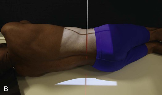
Position of part
• Center the midsagittal plane of the patient's body to the midline of the grid.
• Adjust the patient's shoulders and hips to lie in the same horizontal plane.
• Flex the patient's elbows, and place the hands on the upper chest so that the forearms do not lie within the exposure field.
• A radiolucent support under the lower pelvic side can be used to reduce rotation when necessary.
• Reduce lumbar lordosis by flexing the patient's hips and knees enough to place the back in firm contact with table (see Fig. 8-86).
• To show the lumbar spine and sacrum, center the 14 × 17 inch (35 × 43 cm) IR at the level of the iliac crests (L4). Carefully palpate the crest of the ilium. It is possible to be misled by the contour of the heavy muscles and fatty tissue lying above the bone.
• To show the lumbar spine only, center the IR 1.5 inches (3.8 cm) above the iliac crest (L3). An 11 × 14 inch (30 × 35 cm) IR can be used, if available.
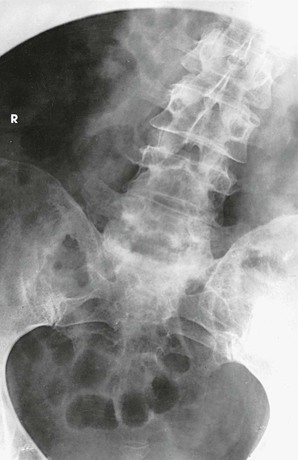
Structures shown, AP and PA
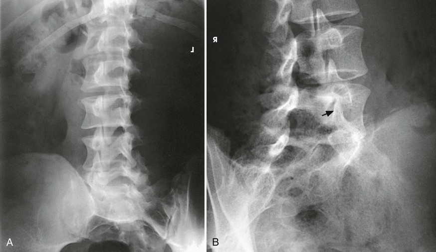
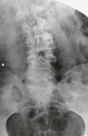
The image shows the lumbar bodies, intervertebral disk spaces, interpediculate spaces, laminae, and spinous and transverse processes (Fig. 8-88). The images may include one or two of the lower thoracic vertebrae, the sacrum coccyx, and the pelvic bones. Because of the angle at which the last lumbar segment joins the sacrum, this lumbosacral disk space is not shown well in the AP projection. The positions used for this purpose are described in the next several sections.
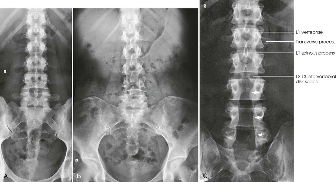
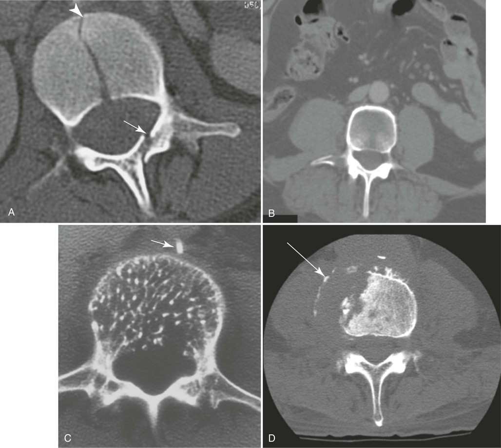
A radiologist may request or prefer that the AP projection be performed with the collimator open to the IR size. This projection provides additional information about the abdomen, in particular when the projection is done for trauma purposes. The larger field enables visualization of the liver, kidney, spleen, and psoas muscle margins along with air or gas patterns (see Fig. 8-88, B). CT and magnetic resonance imaging (MRI) are used often specifically to identify pathology (Fig. 8-89).
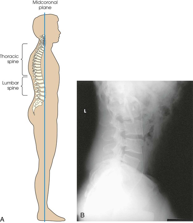
Lateral Projection
R or L position
Image receptor: 11 × 14 inch (30 × 35 cm) or 14 × 17 inch (35 × 43 cm), depending on availability
Position of part
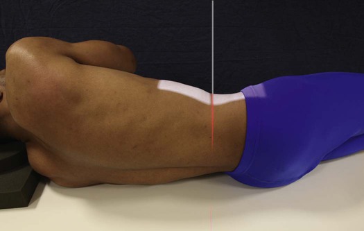
• Ask the patient to turn onto the affected side and flex the hips and knees to a comfortable position.
• When examining a thin patient, adjust a suitable pad under the dependent hip to relieve pressure.
• Align the midcoronal plane of the body to the midline of the grid and ensure that it is vertical. On most patients, the long axis of the bodies of the lumbar spine is situated in the midcoronal plane (Fig. 8-90).
• With the patient's elbow flexed, adjust the dependent arm at right angles to the body.
• To prevent rotation, superimpose the knees exactly, and place a small sandbag between them.
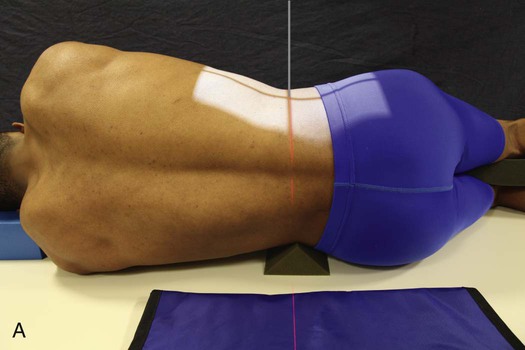
• Place a suitable radiolucent support under the lower thorax, and adjust it so that the long axis of the spine is horizontal (Fig. 8-91, A). This is the preferred method of positioning the spine.
• When using a 14 × 17 inch (35 × 43 cm) IR, center it at the level of the crest of the ilium (L4).
• To show the lumbar spine only, center the IR 1.5 inches (3.8 cm) above the iliac crest (L3). An 11 × 14 inch (30 × 35 cm) IR can be used, if available.
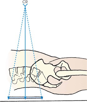
Central ray
• Perpendicular; at the level of the crest of the ilium (L4) when a 14 × 17 inch (35 × 43 cm) IR is used or 1.5 inches (3.8 cm) above the iliac crest (L3) when a 11 × 14 inch (30 × 35 cm) IR is used. The central ray enters the midcoronal plane (see Fig. 8-91, A).
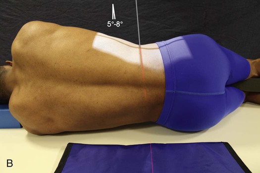
• When the spine cannot be adjusted so that it is horizontal, angle the central ray caudad so that it is perpendicular to the long axis (Fig. 8-91, B). The degree of central ray angulation depends on the angulation of the lumbar column and the breadth of the pelvis. In most instances, an average caudal angle of 5 degrees for men and 8 degrees for women with a wide pelvis is used. CR placement must be adjusted slightly based on the angle used.
Structures shown
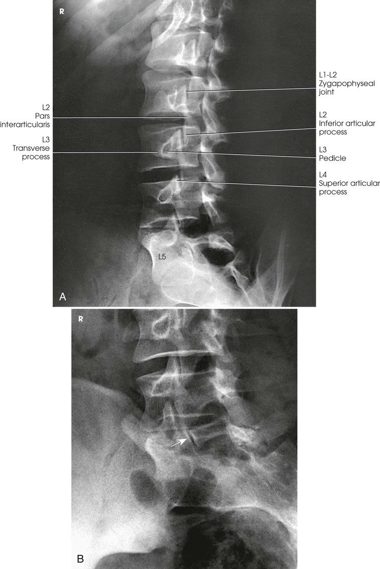
The image shows the lumbar bodies and their intervertebral disk spaces, the spinous processes, and the lumbosacral junction (Fig. 8-92). This projection gives a profile image of the intervertebral foramina of L1-4. The L5 intervertebral foramina (right and left) are not usually well seen in this projection because of their oblique direction. Consequently, oblique projections are used for these foramina.

Improving radiographic quality
In addition to close collimation, the quality of the radiographic image can be improved in several ways. A 48-inch (112-cm) or greater SID is recommended to reduce the magnification inherent in this image because OID of the lumbar spine is significant in this projection. In addition, if a sheet of leaded rubber is placed on the table behind the patient (see Fig. 8-91), the lead absorbs scatter radiation coming from the patient and prevents table scatter. Scatter radiation decreases the quality of the radiograph and darkens the image of the spinous processes. More important, with AEC, scatter radiation coming from the patient is often sufficient to terminate the exposure prematurely. As a result, the image may be underexposed.
L5-S1 Lumbosacral Junction
Lateral Projection
R or L position
Image receptor: 8 × 10 inch (18 × 24 cm) or 10 × 12 inch (24 × 30 cm), depending on availability
Position of part
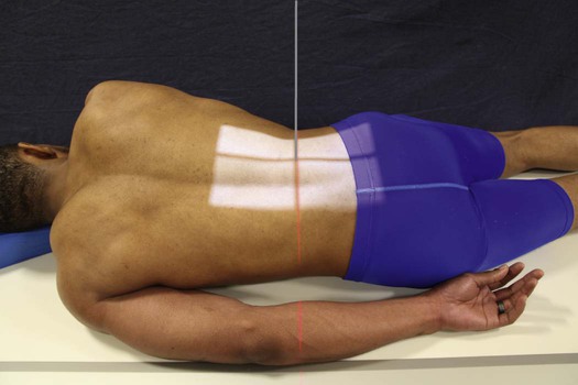
• With the patient in the recumbent position, adjust the pillow to place the midsagittal plane of the head in the same plane with the spine.
• Adjust the midcoronal plane of the body (passing through the hips and shoulders) so that it is perpendicular to the IR.
• Flex the patient's elbow, and adjust the dependent arm in a position at right angles to the body (Fig. 8-93, A).
• Flex the patient's hips and knees, superimpose the knees, and place a support between them.
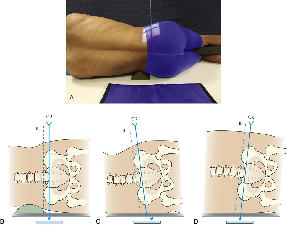
• As described for the lateral projection, place a radiolucent support under the lower thorax and adjust it so that the long axis of the spine is horizontal (see Fig. 8-93, A). This is the preferred method.
Central ray
• The elevated anterior superior iliac spine (ASIS) is easily palpated and found in all patients when lying on the side. The ASIS provides a standardized and accurate reference point from which to center the L5-S1 junction.
• Center on a coronal plane 2 inches (5 cm) posterior to the ASIS and 1.5 inches (3.8 cm) inferior to the iliac crest.
• Center the IR to the central ray.
• When the spine is not in the true horizontal position, the central ray is angled 5 degrees caudally for male patients and 8 degrees caudally for female patients.
• Francis1 identified an alternative technique to show the open L5-S1 intervertebral disk space when the spine is not horizontal:
1. With the patient in the lateral position, locate both iliac crests.
2. Draw an imaginary line between the two points (interiliac plane).
3. Adjust central ray angulation to be parallel with the interiliac line (Fig. 8-93, B to D).
Structures shown
The resulting image shows a lateral projection of the lumbosacral junction, the lower one or two lumbar vertebrae, and the upper sacrum (Fig. 8-94).

Lumbar Zygapophyseal Joints
AP Oblique Projection
RPO and LPO positions
The plane of the zygapophyseal joints of the lumbar vertebrae forms an angle of 30 to 60 degrees to the midsagittal plane in most patients. The angulation varies from patient to patient, however, and from cephalad to caudad and side to side in the same patient (see Table 8-3). For comparison, radiographs are generally obtained from both sides.
Image receptor: 10 × 12 inch (24 × 30 cm), 11 × 14 inch (30 × 35 cm) or 14 × 17 inch (35 × 43 cm) lengthwise, depending on availability and department protocol. 8 × 10 inch (18 × 24 cm) or 10 × 12 inch (24 × 30 cm) for the L5-S1 zygapophyseal joint
Position of part
• Have the patient turn from the supine position toward the affected side approximately 45 degrees to show the joints closest to the IR (opposite the thoracic zygapophyseal joints).
• Adjust the patient's body so that the long axis of the patient is parallel with the long axis of the radiographic table.
• Center the patient's spine to the midline of the grid. In the oblique position, the lumbar spine lies in the longitudinal plane that passes 2 inches (5 cm) medial to the elevated ASIS.
• Ask the patient to place the arms in a comfortable position. A support may be placed under the elevated shoulder, hip, and knee to avoid patient motion (Figs. 8-95 and 8-96).

• Check the degree of body rotation, and make any necessary adjustments. An oblique body position 60 degrees from the plane of the IR may be needed to show the L5-S1 zygapophyseal joint and articular processes.
NOTE: Although the customary 45-degree oblique body position shows most L3-S1 zygapophyseal joint spaces, 25% of L1-2 and L2-3 joints are shown on an AP projection, and a small percentage of L4-5 and L5-S1 joints are seen on a lateral projection.1
Structures shown
The resulting image shows an oblique projection of the lumbar or lumbosacral spine or both, showing the articular processes of the side closest to the IR. Both sides are examined for comparison (Figs. 8-97 and 8-98).

When the body is placed in a 45-degree oblique position and the lumbar spine is radiographed, the articular processes and the zygapophyseal joints are shown. When the patient has been properly positioned, images of the lumbar vertebrae have the appearance of Scottie dogs. Fig. 8-97 shows the vertebral structures that compose the Scottie dog. (See Summary of Oblique Projections, p. 382.)
Evaluation Criteria
The following should be clearly shown:
▪ Evidence of proper collimation
▪ Area from the lower thoracic vertebrae to the sacrum
▪ Zygapophyseal joints closest to the IR—open and uniformly visible through the vertebral bodies
▪ When the joint is not well seen, and the pedicle is anterior on the vertebral body, patient not rotated enough (Fig. 8-99, A).

▪ When the joint is not well seen, and the pedicle is posterior on the vertebral body, patient rotated too much (Fig. 8-99, B).
▪ Vertebral column parallel with the tabletop so that T12-L1 and L1-2 intervertebral joint spaces remain open
PA Oblique Projection
RAO and LAO positions
Image receptor: 10 × 12 inch (24 × 30 cm), 11 × 14 inch (30 × 35 cm), or 14 × 17 inch (35 × 43 cm) lengthwise, depending on availability and department protocol. 8 × 10 inch (18 × 24 cm) or 10 × 12 inch (24 × 30 cm) for L5-S1 zygapophyseal joint
Position of patient
• Examine the patient in the upright or recumbent prone position. The recumbent position is generally used because it facilitates immobilization.
• Greater ease in positioning the patient and a resultant higher percentage of success in duplicating results make the semiprone position preferable to the semisupine position. The OID is increased, however, which can affect resolution.
Position of part
• The joints farthest from the IR are shown with the PA oblique projection (opposite thoracic zygapophyseal joints).
• From the prone position, have the patient turn to a semiprone position and support the body on the forearm and flexed knee.
• Align the body to center L3 to the midline of the grid (Fig. 8-100).
• Adjust the degree of body rotation to an angle of 45 degrees. An oblique body position 60 degrees from the plane of the IR may be needed to show the L5-S1 zygapophyseal joints and articular processes.
• Center the IR at the level of L3.
• To show the lumbosacral joint, position the patient as described previously but center L5.
Structures shown
The image shows an oblique projection of the lumbar or lumbosacral vertebrae, showing the articular processes of the side farther from the IR (Figs. 8-101 to 8-103). The T12-L1 articulation between the twelfth thoracic and first lumbar vertebrae, having the same direction as those in the lumbar region, is shown on the larger IR. The fifth lumbosacral joint is usually well shown in oblique positions (see Fig. 8-103).


When the body is placed in a 45-degree oblique position, and the lumbar spine is radiographed, the articular processes and zygapophyseal joints are shown. When the patient has been properly positioned, images of the lumbar vertebrae have the appearance of Scottie dogs. Fig. 8-101 identifies the vertebral structures that compose the Scottie dog. (See Summary of Oblique Projections, p. 382.)
Lumbosacral Junction and Sacroiliac Joints
AP or PA Axial Projection
Ferguson Method1
Image receptor: 8 × 10 inch (18 × 24 cm) or 10 × 12 inch (24 × 30 cm) lengthwise, depending on availability
Position of part
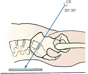
• With the patient supine and the midsagittal plane centered to the grid, extend the patient's lower limbs or abduct the thighs and adjust in the vertical position (Fig. 8-104).

Central ray
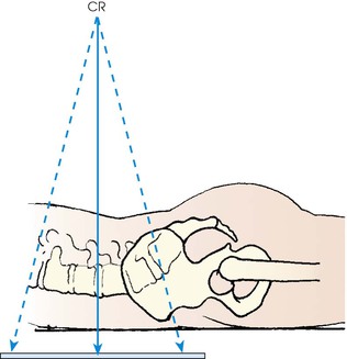
• Directed through the lumbosacral joint at an average angle of 30 to 35 degrees cephalad1
• An angulation of 30 degrees in male patients and 35 degrees in female patients is usually satisfactory. By noting the contour of the lower back, unusual accentuation or diminution of the lumbosacral angle can be estimated, and the central ray angulation can be varied accordingly.
• The central ray enters the midsagittal plane at a point about 1.5 inches (3.8 cm) superior to the pubic symphysis or 2 to 2.5 inches (5 to 6.5 cm) inferior to the ASIS (Fig. 8-105).
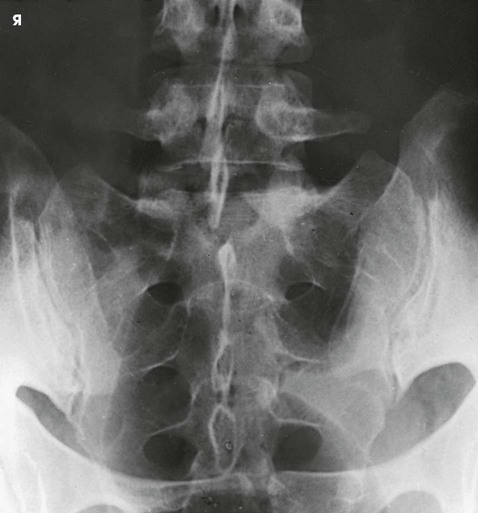
Structures shown
The resulting image shows the lumbosacral joint and a symmetric image of both sacroiliac joints free of superimposition (Fig. 8-106).

Evaluation Criteria
The following should be clearly shown:
▪ Evidence of proper collimation
▪ Lumbosacral junction and sacrum
▪ Open intervertebral disk space between L5 and S1
NOTE: The PA axial projection for the lumbosacral junction can be modified in accordance with the AP axial projection just described. With the patient in the prone position, the central ray is directed through the lumbosacral joint to the midpoint of the IR at an average angle of 35 degrees caudad. The central ray enters the spinous process of L4 (Figs. 8-107 and 8-108).

Meese1 recommended the prone position for examinations of the sacroiliac joints because their obliquity places them in a position more nearly parallel with the divergence of the beam of radiation. The central ray is directed perpendicularly and is centered at the level of the ASIS. It enters the midline of the patient about 2 inches (5 cm) distal to the spinous process of L5 (Fig. 8-109).

Sacroiliac Joints
AP Oblique Projection
RPO and LPO positions
Image receptor: 8 × 10 inch (18 × 24 cm) or 10 × 12 inch (24 × 30 cm) lengthwise, depending on availability. Both obliques are usually obtained for comparison.
Position of part
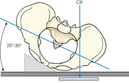
• Elevate the side of interest approximately 25 to 30 degrees, and support the shoulder, lower thorax, and upper thigh (Figs. 8-110 and 8-111).

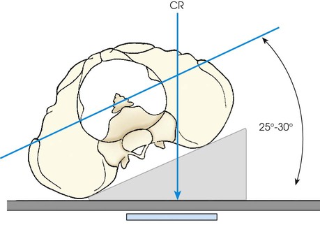
• The side being examined is farther from the IR. Use the LPO position to show the right joint and the RPO position to show the left joint.
• Adjust the patient's body so that its long axis is parallel with the long axis of the radiographic table.
• Align the body so that a sagittal plane passing 1 inch (2.5 cm) medial to the ASIS of the elevated side is centered to the midline of the grid.
• Check the rotation at several points along the back.
• Center the IR at the level of the ASIS.
• Shield gonads. Collimating close to the joint may shield the gonads in male patients. It may be difficult to use contact shielding in female patients.
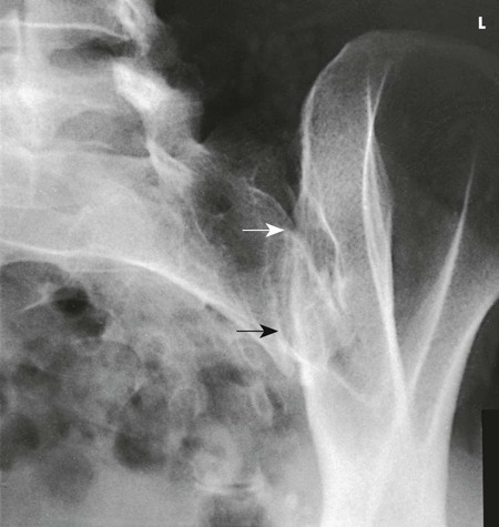
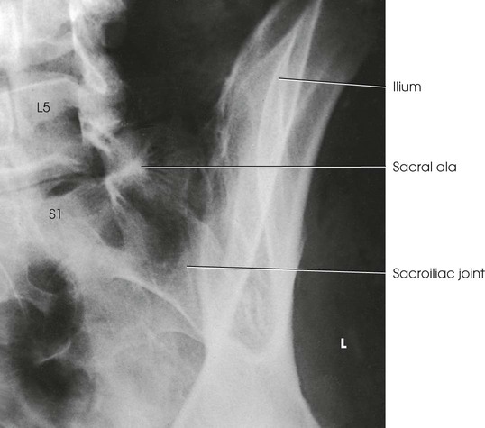
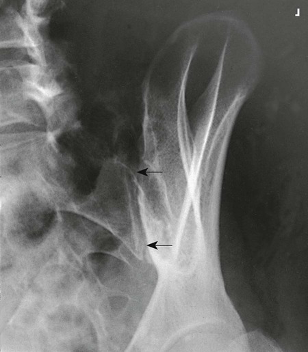
Structures shown
The image shows the sacroiliac joint farthest from the IR and an oblique projection of the adjacent structures. Both sides are examined for comparison (Fig. 8-112). (See Summary of Oblique Projections, p. 382.)
Evaluation Criteria
The following should be clearly shown:
▪ Evidence of proper collimation
▪ Open sacroiliac joint space with minimal overlapping of the ilium and sacrum
NOTE: An AP axial oblique can be obtained by positioning the patient as described. For the AP axial oblique, the central ray is directed at an angle of 20 to 25 degrees cephalad, entering 1 inch (2.5 cm) medial and  inches (3.8 cm) distal to the elevated ASIS (Fig. 8-113).
NOTE: Brower and Kransdorf1 summarized difficulties in imaging the sacroiliac joints because of patient positioning and variability.
PA Oblique Projection
RAO and LAO positions
Image receptor: 8 × 10 inch (18 × 24 cm) or 10 × 12 inch (24 × 30 cm) lengthwise, depending on availability. Both obliques are usually obtained for comparison.
Position of part
• Adjust the patient by rotating the side of interest toward the radiographic table until a body rotation of 25 to 30 degrees is achieved. Have the patient rest on the forearm and flexed knee of the elevated side.
• The side being examined is closer to the IR. Use the RAO position to show the right joint and the LAO position to show the left joint.
• Check the degree of rotation at several points along the anterior surface of the patient's body.
• Adjust the patient's body so that its long axis is parallel with the long axis of the table.
• Center the body so that a point 1 inch (2.5 cm) medial to the ASIS closest to the IR is centered to the grid (Figs. 8-114 and 8-115).

• Center the IR at the level of the ASIS.
• Shield gonads. Collimating close to the joint may shield the gonads in male patients. It may be difficult to use contact shielding in female patients.
Structures shown
The resulting image shows the sacroiliac joint closest to the IR (Fig. 8-116). (See Summary of Oblique Projections, p. 382.)
Evaluation Criteria
The following should be clearly shown:
▪ Evidence of proper collimation
▪ Open sacroiliac joint space closest to the IR or minimal overlapping of the ilium and sacrum
NOTE: A PA axial oblique can be obtained by positioning the patient as described previously. For the PA axial oblique, the central ray is directed 20 to 25 degrees caudad to enter the patient at the level of the transverse plane, pass  inches (3.8 cm) distal to the L5 spinous process, and exit at the level of the ASIS (Fig. 8-117).

Sacrum and Coccyx
AP and PA Axial Projections
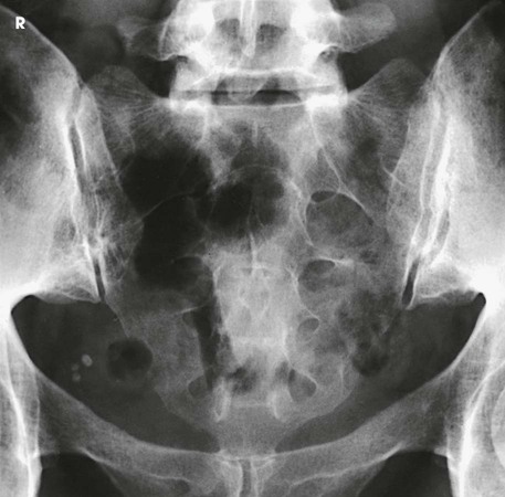
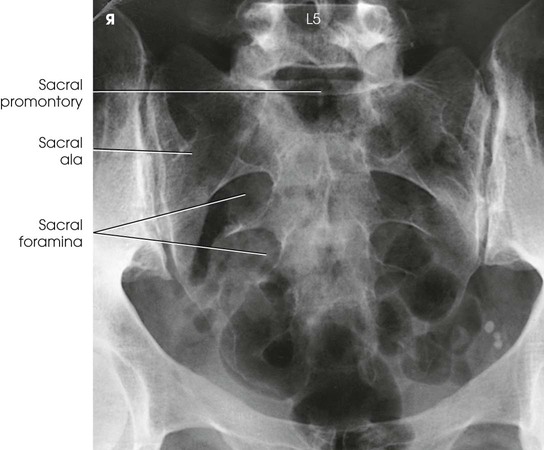
Because bowel content may interfere with the image, the colon should be free of gas and fecal material for examinations of the sacrum and coccyx. A physician's order for a bowel preparation may be needed. The urinary bladder should be emptied before the examination.
Image receptor: 10 × 12 inch (24 × 30 cm) for sacrum; 8 × 10 inch (18 × 24 cm) for coccyx, if available
Position of patient
• Place the patient in the supine position for the AP axial projection of the sacrum and coccyx so that the bones are as close as possible to the IR. The supine position is most often used. The prone position can be used without appreciable loss of detail and is particularly appropriate for patients with a painful injury or destructive disease.
Position of part
• With the patient either supine or prone, center the midsagittal plane of the body to the midline of the table grid.
• Adjust the patient so that both ASIS are equidistant from the grid.
• Have the patient flex the elbows and place the arms in a comfortable, bilaterally symmetric position.
• When the supine position is used, place a support under the patient's knees.
• Shield gonads on men. Women cannot be shielded for this projection.
Central ray
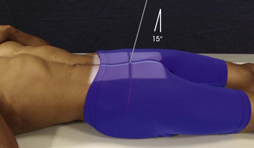
• With the patient supine, direct the central ray 15 degrees cephalad and center it to a point 2 inches (5 cm) superior to the pubic symphysis (Figs. 8-118 to 8-120).

• With the patient prone, angle the central ray 15 degrees caudad and center it to the clearly visible sacral curve (Fig. 8-121).
Coccyx
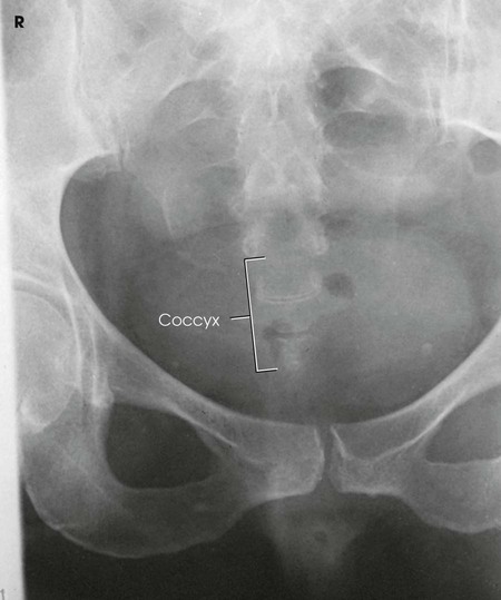
• With the patient supine, direct the central ray 10 degrees caudad and center it to a point about 2 inches (5 cm) superior to the pubic symphysis (Figs. 8-122 and 8-123).

• With the patient prone, angle the central ray 10 degrees cephalad and center it to the easily palpable coccyx.
Structures shown
The resulting image shows the sacrum or coccyx free of superimposition (see Figs. 8-120, 8-121, and 8-123).
Lateral Projections
R or L position
Image receptor: 10 × 12 inch (24 × 30 cm) for sacrum; 8 × 10 inch (18 × 24 cm) lengthwise for coccyx, if available
Position of part
• Adjust the arms in a position at right angles to the body.
• Superimpose the knees, and, if needed, place positioning sponges under and between the ankles and between the knees.
• Adjust a support under the body to place the long axis of the spine horizontal. The interiliac plane is perpendicular to the IR.
• Adjust the pelvis and shoulders so that the true lateral position is maintained (i.e., no rotation) (Figs. 8-124 and 8-125).
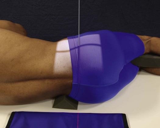

• To prepare for accurate positioning of the central ray, center the sacrum or coccyx to the midline of the grid.
Central ray
• The elevated ASIS is easily palpated and found on all patients when they are lying on their side and provides a standardized reference point from which to center the sacrum and coccyx (Fig. 8-126).

Structures shown
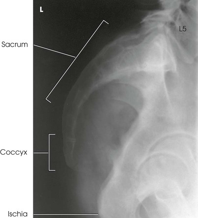
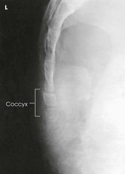
The resulting image shows a lateral projection of the sacrum or coccyx (Figs. 8-127 and 8-128).
Improving radiographic quality
The quality of the radiograph can be improved if a sheet of leaded rubber is placed on the table behind the patient (see Figs. 8-124 and 8-125). The lead absorbs the scatter radiation coming from the patient. Scatter radiation decreases the quality of the radiograph. More important, with AEC, the scatter radiation coming from the patient is often sufficient to terminate the exposure prematurely, resulting in an underexposed radiograph. For the same reason, close collimation is necessary for lateral sacrum and coccyx images. This is crucial when computed radiography is used.
Lumbar Intervertebral Disks
PA Projection
WEIGHT-BEARING METHOD
R and L bending
Image receptor: 14 × 17 inch (35 × 43 cm) lengthwise
Position of patient
• Perform this examination with the patient in the standing position. Duncan and Hoen1 recommended that the PA projection be used because in this direction the divergent rays are more nearly parallel with the intervertebral disk spaces.
Position of part
• With the patient facing the vertical grid device, adjust the height of the IR to the level of L3.
• Adjust the patient's pelvis for rotation by ensuring that the ASIS are equidistant from the IR.
• Center the midsagittal plane of the patient's body to the midline of the vertical grid device (Fig. 8-129).
• Let the patient's arms hang unsupported by the sides.
• Make one radiograph with the patient bending to the right and one with the patient bending to the left (Fig. 8-130).
• Have the patient lean directly lateral as far as possible without rotation and without elevation of the foot. The degree of bending must not be forced, and the patient must not be supported in position.
• Ensure that the midsagittal plane of the lower lumbar column and sacrum remains centered to the grid device as the upper portion moves laterally.
Structures shown
The resulting images show bending PA projections of the lower thoracic region and the lumbar region for demonstration of the mobility of the cartilaginous intervertebral joints. In patients with disk protrusion, this type of examination is used to localize the involved joint, as shown by limitation of motion at the site of the lesion (see Fig. 8-130).
Radiation protection
The PA projection is recommended instead of the AP projection whenever the clinical information provided by the examination is not compromised. With the PA projection, the patient's gonad area and breast tissue receive significantly less radiation than when the AP projection is used. In addition, proper collimation reduces the radiation dose to the patient. Lead shielding material should be placed between the x-ray tube and a male patient's gonads to protect this area further from unnecessary radiation.
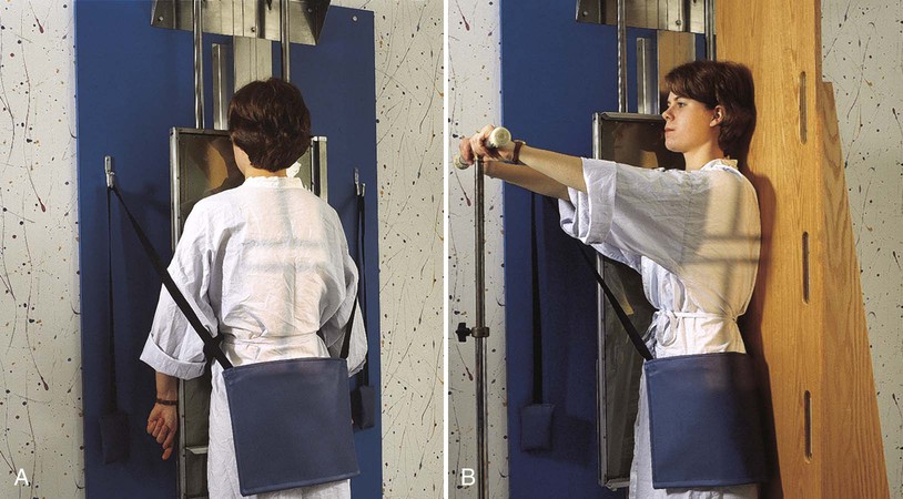
Thoracolumbar Spine: Scoliosis
PA and Lateral Projections
Frank et al. Method1-3
The method described has been endorsed by the American College of Radiology, the Academy of Orthopedic Physicians, and the Center for Development and Radiation Health of the Department of Health and Human Services. Endorsement includes use of the PA projection, compensating filters, and lateral breast protection, and nonuse of graduated screens.
Scoliosis is an abnormal lateral curvature of the vertebral column with some associated rotation of the vertebral bodies at the curve. This condition may be caused by disease, surgery, or trauma, but it is frequently idiopathic. Scoliosis is commonly detected in the adolescent years. If not detected and treated, it may progress to the point of debilitation.
Diagnosis and monitoring of scoliosis requires a series of radiographs that may include upright, supine, and bending studies. A typical scoliosis study might include the following projections:
The PA (or AP) and lateral upright projections show the amount or degree of curvature that occurs with the force of gravity acting on the body (Fig. 8-131). Spinal fixation devices, such as Harrington rods, may also be evaluated. Bending studies are often used to differentiate between primary and compensatory curves. Primary curves do not change when the patient bends, whereas secondary curves do change with bending.
Because scoliosis is generally diagnosed and evaluated during the teenage years, proper radiographic techniques are important. The wide range of body part thicknesses and specific gravities in the thoracic and abdominal areas necessitates the use of compensating filters. Historically, large film-screen systems and grids, such as 14 × 36 inch (35 × 90 cm), were used to show the entire spine with one exposure. To expose the length of the 36-inch (90-cm) IR, a minimum 60-inch (152-cm) SID is used.
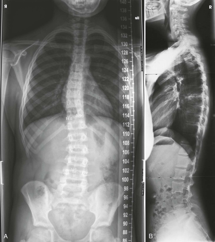
Digital imaging
• Advances in digital imaging have changed the way scoliosis radiography is performed. A variety of devices and IR holders have been developed for both CR and DR systems. All systems allow multiple images encompassing the entire spine to be captured without the need for repositioning of the patient. The acquired images are combined, or “stitched,” by the computer system into a composite image that demonstrates the entire spine in one image (Fig. 8-132, A).
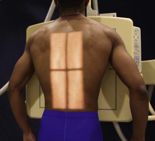
Collimation
• Extent of collimation depends on the type of imaging system used, as well as the extent of the patient's scoliosis. Care should be taken to include only the anatomy of interest. If possible, the width of the collimated field should be less than the width of the IR. Always check previous examination images to determine extent of curvature.
Radiation protection
In 1983, Frank et al.1 described use of the PA projection for radiography of scoliosis. Also in 1983, Frank and Kuntz2 described a simple method of protecting the breasts during radiography of scoliosis. By 1986, the federal government had endorsed the use of these techniques in an article by Butler et al.3
Radiation protection is crucial. Collimation must be closely limited to irradiate only the thoracic and lumbar spine. The gonads should be shielded by placing a lead apron at the level of the ASIS between the patient and the x-ray tube. The breasts should be shielded with leaded rubber or leaded acrylic (see Figs. 8-132 and 8-133), or the breast radiation exposure should be decreased by performing PA projections.
PA Projection
Ferguson Method1
The patient should be positioned to obtain a PA projection (in lieu of the AP projection) to reduce radiation exposure2 to selected radiosensitive organs. The decision whether to use a PA or AP projection is often determined by physician or institutional policy.
Image receptor: 14 × 36 inch (35 × 90 cm) or 14 × 17 inch (35 × 43 cm) lengthwise, depending on imaging system used
Position of patient
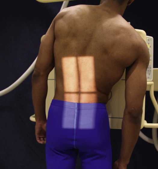
• For a PA projection, place the patient in a seated or standing position in front of a vertical grid device.
• Have the patient sit or stand straight, and then adjust the height of the IR to include about 1 inch (2.5 cm) of the iliac crests (Fig. 8-134).
Position of part
• Adjust the patient in a normally seated or standing position to check the spinal curvature.
• Center the midsagittal plane of the patient's body to the midline of the grid.
• Allow the patient's arms to hang relaxed at the sides. If the patient is seated, flex the elbows and rest the hands on the lap (Fig. 8-135).
Second radiograph
• Elevate the patient's hip or foot on the convex side of the primary curve approximately 3 or 4 inches (7.6 to 10.2 cm) by placing a block, a book, or sandbags under the buttock or foot (Fig. 8-136). Ferguson1 specified that the elevation must be sufficient to make the patient expend some effort in maintaining the position.

• Do not support the patient in these positions.
• Do not employ a compression band.
• Obtain additional radiographs (if needed) with elevation of the hip on the side opposite the major or primary curve (Fig. 8-137) or with the patient in a recumbent position (Fig. 8-138).
Collimation
• Extent of collimation depends on the type of imaging system used, as well as the severity of the patient's scoliosis. Care should be taken to include only the anatomy of interest. The width of the collimated field must be less than the width of the IR. Always check previous examination images to determine extent of curvature.
Structures shown
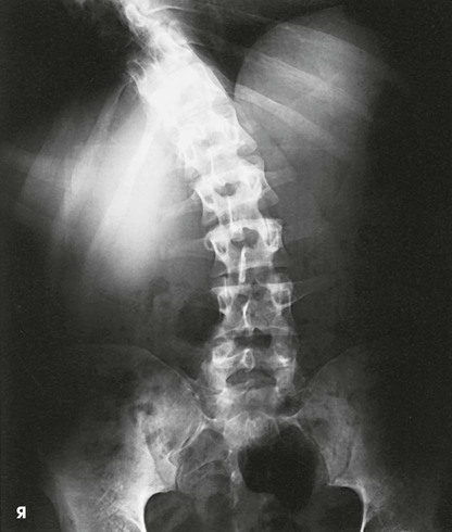
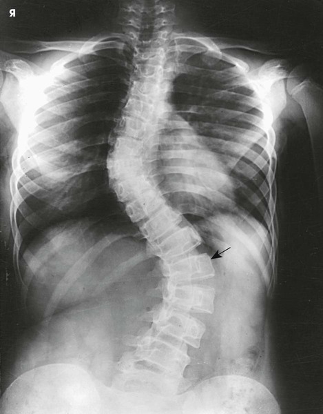
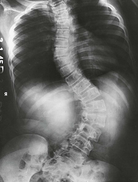
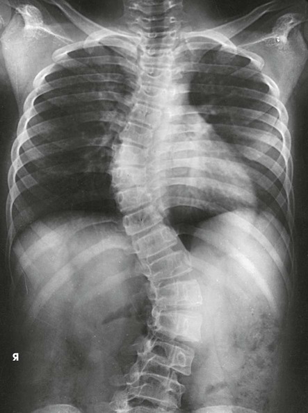
The resulting images show PA projections of the thoracic and lumbar vertebrae, which are used for comparison to distinguish the deforming or primary curve from the compensatory curve in patients with scoliosis (see Figs. 8-135 to 8-138).
Lumbar Spine: Spinal Fusion
AP Projection
R and L bending
Image receptor: 10 × 12 inch (24 × 30 cm) or 14 × 17 inch (35 × 43 cm) lengthwise for each exposure
Position of part
• Make the first radiograph with maximum right bending, and make the second radiograph with maximum left bending.
• To obtain equal bending force throughout the spine, cross the patient's leg on the opposite side to be flexed over the other leg. A right bending requires the left leg to be crossed over the right.
• Move both of the patient's heels toward the side that is flexed. Immobilize the heels with sandbags.
• Move the shoulders directly lateral as far as possible without rotating the pelvis (Fig. 8-139).

• After the patient is in position, apply a compression band to prevent movement.
Structures shown
The resulting images show AP projections of the lumbar vertebrae, made in maximum right and left lateral flexion (Figs. 8-140 and 8-141). These studies are used in patients with early scoliosis to determine the presence of structural change when bending to the right and left. The studies are also used to localize a herniated disk, as shown by limitation of motion at the site of the lesion, and to show whether there is motion in the area of a spinal fusion. The latter examination is usually performed 6 months after the fusion operation.
Lateral Projection
R or L position
Hyperflexion and hyperextension
Image receptor: 14 × 17 inch (35 × 43 cm) lengthwise for each exposure
Position of part
• For the first radiograph, have the patient bend forward to flex the spine as much as possible (Fig. 8-142).


• For the second radiograph, have the patient bend backward to extend the spine as much as possible (Fig. 8-143).

• Immobilize the patient to prevent movement, if needed.
Structures shown
The resulting images show two lateral projections of the spine made in hyperflexion (Fig. 8-144, A) and hyperextension (Fig. 8-144, B) to determine whether motion is present in the area of a spinal fusion, indicating a non-union, or to localize a herniated disk as shown by limitation of motion at the site of the lesion.