Long Bone Measurement
Imaging Methods
Long bone measurement to evaluate for limb length discrepancy may be accomplished by radiography, microdose digital radiography, ultrasonography (US), computed tomography (CT), and magnetic resonance imaging (MRI).1 Radiographic methods are the orthoroentgenogram, scanogram, and teleoroentgenogram. Both the orthoroentgenogram and the scanogram require three precisely centered exposures at the hip, knee, and ankle joints and include the use of a radiopaque ruler taped to the table between the limbs. The image receptor (IR) size is the primary difference, with the orthoroentgenogram using a single IR that remains stationary while the table and the x-ray tube move to an unexposed section. The scanogram technique uses three separate IRs. The teleoroentgenogram is a single upright AP exposure of both limbs on a special long IR at an SID of at least 6 ft (180 cm). Digital imaging usually employs a hybrid of these traditional techniques by obtaining the three exposures centered at the hip, knee, and ankle joints with the patient standing upright. Digital postprocessing “stitches” the three images together for equally accurate measurements of the entire lower limbs with lower radiation dose than is used in the film-screen methods.1,2 Although studies are occasionally made of the upper limbs, radiography is most frequently applied to the lower limbs. This chapter explains patient positioning for the three joint exposures, as well as for CT scanograms.
Radiation Protection
Differences in limb length are common in children and may occur in association with various disorders. Patients with unequal limb growth may require yearly imaging evaluations. More frequent examinations may be necessary in patients who have undergone surgical procedures to equalize limb length. For these reasons, radiation protection is a primary consideration in imaging for long bone measurement. Gonad shielding is necessary, as are careful patient positioning, secure immobilization, and accurate centering of a closely collimated beam of radiation to prevent unnecessary repeat exposures. Microdose digital radiography yields the lowest dose but requires specialized equipment, which can be cost-prohibitive. MRI and US have promise as means to safely image for long bone measurement, with recent research demonstrating 99% accuracy and reliability for MRI measurements.1,3
Position of Patient
Three exposures of each limb are made, with the accuracy of the examination depending on the patient not moving the limb or limbs even slightly. Small children must be carefully immobilized to prevent motion. If movement of the limb occurs before the examination is completed, all images may need to be repeated.
• Place the patient in the supine position for orthoroentgenography and scanography.
• Stand the patient upright backed up closely to the vertical Bucky device for a digital teleoroentgenogram.
• Both sides are examined for comparison either separately or simultaneously for all techniques.
• When a soft tissue abnormality (swelling or atrophy) is causing rotation of the pelvis, elevate the low side on a radiolucent support to overcome the rotation, if necessary.
Position of Part
The limb to be examined should be positioned as follows:
• Adjust and immobilize the limb for an AP projection.
• If the two lower limbs are examined simultaneously, separate the ankles 5 to 6 inches (13 to 15 cm) and place the specialized ruler under the pelvis and extended down between the legs.
• If the limbs are examined separately, position the patient with a special ruler beneath each limb.
• When the knee of the patient's abnormal side cannot be fully extended, flex the normal knee to the same degree and support each knee on one of a pair of supports of identical size to ensure that the joints are flexed to the same degree and are equidistant from the image receptor (IR).
Localization of Joints
For methods that require centering of the central ray above the joints, the following steps should be taken:
• Localize each joint accurately, and use a skin-marking pencil to indicate the central ray centering point.
• Because both sides are examined for comparison and a discrepancy in bone length usually exists, mark the joints of each side after the patient is in the required position.
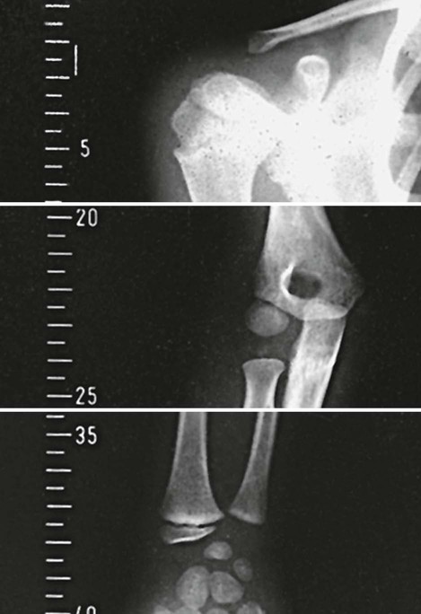
• With the upper limb, place the marks as follows: for the shoulder joint, over the superior margin of the head of the humerus; for the elbow joint,  to
to  inch (1.3 to 1.9 cm) below the plane of the epicondyles of the humerus (depending on the size of the patient); and for the wrist, midway between the styloid processes of the radius and ulna.
• With the lower limb, locate the hip joint by placing a mark 1 to  inches (2.5 to 3.2 cm) (depending on the size of the patient) laterodistally and at a right angle to the midpoint of an imaginary line extending from the anterior superior iliac spine to the pubic symphysis.
• Locate the knee joint just below the apex of the patella at the level of the depression between the femoral and tibial condyles.
• Locate the ankle joint directly below the depression midway between the malleoli.
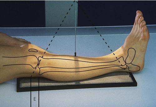
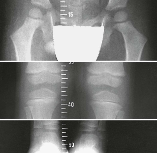
In all images made by a single x-ray exposure, the image is larger than the actual body part because the x-ray photons start at a small area on the target of the x-ray tube and diverge as they travel in straight lines through the body to the IR (Fig. 11-1). This magnification can be decreased by putting the body part as close to the IR as possible and using the maximum SID allowed by the equipment. For orthoroentgenography, a metal measurement ruler is placed between the patient's lower limbs, and three exposures are made on the same x-ray IR. The following steps are taken:
• Using narrow collimation and careful centering of limb parts to the upper, middle, and lower thirds of the IR, make three exposures on one IR.
• For all three exposures, place the central ray perpendicular to and passing directly through the specified joint (hence the term orthoroentgenology, from the Greek word orthos, meaning “straight”).
• Do not move the limb between exposures. Because the IR is in the Bucky tray for all exposures including exposure of the ankle, exposure factors must be modified accordingly.
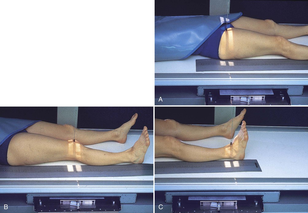
• Position the x-ray tube directly over the patient's hip, and make the first exposure (Fig. 11-2, A).
• Move the x-ray tube directly over the patient's knee joint, and make a second exposure (Fig. 11-2, B).
• Move the x-ray tube directly over the patient's ankle joint, and make a third exposure (Fig. 11-2, C).
If the child holds the leg perfectly still while the three exposures are made, the true distance from the proximal end of the femur to the distal end of the tibia can be directly measured on the image, as follows:
• Place a special metal ruler (engraved with radiopaque  -inch [1.3-cm] marks that show when an image is made) under the leg and on top of the table (see Fig. 11-2).
• If the IR is placed in the Bucky tray and then is moved between exposures, as for a scanogram (see Fig. 11-2), calculate the length of the femur and tibia by subtracting the numeric values projected over the two joints obtained by simultaneously exposing the patient and the metal ruler.
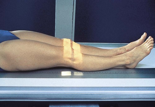
Another method of measuring the length of the femurs and tibias is to examine both limbs simultaneously (Figs. 11-3 and 11-4):
• Center the midsagittal plane of the patient's body to the midline of the grid.
• Adjust the patient's lower limbs in the anatomic position (i.e., slight medial rotation).
• Tape the special metal ruler to the top of the table so that part of it is included in each of the exposure fields. This records the position of each joint.
• Place an IR in the Bucky tray, and shift it for centering at the three joint levels without moving the patient.
• Center the IR and the tube successively at the previously marked level of the hip joints, the knee joints, and the ankle joints for simultaneous bilateral projections.
• When a difference in level exists between the contralateral joints, center the tube midway between the two levels.
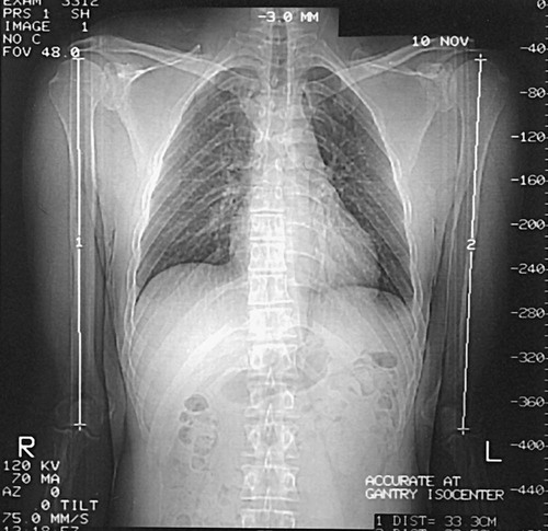
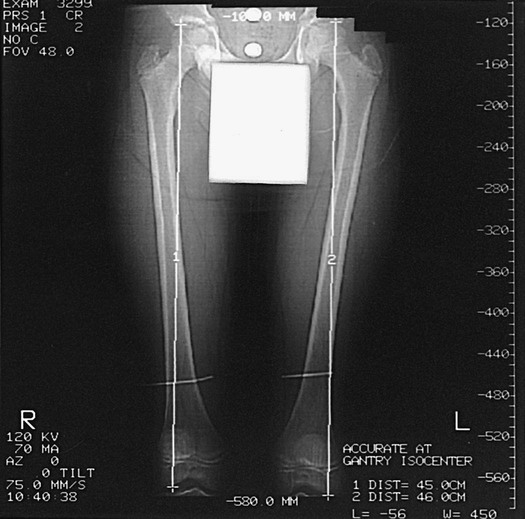
• Digital imaging typically requires three exposures on three separate 14 × 17-inch (35 × 43-cm) IRs with a minimum 6-ft (180-cm) SID. The computer postprocesses the three images into a single image of the entire limb through a process termed “stitching.” Limb length can then be quickly calculated by the computer.1,2
The bilateral orthoroentgenographic method is reasonably accurate if the limbs are of almost the same length. When more than a slight discrepancy in limb length exists (Fig. 11-5), it is impossible to place the center of the x-ray tube exactly over both knee joints and make a single exposure or exactly over both ankle joints and make a single exposure. In such cases, the tube is centered midway between the two joints; however, this results in bilateral distortion because of the diverging x-ray beam. In Fig. 11-5, the measurement obtained for the right femur is less than the actual length of the bone, whereas the measurement of the left femur is greater than the true length. The following measure can be taken to correct this problem:
• Examine each limb separately (Fig. 11-6).
• Center the limb being examined on the grid, and place the special ruler beneath the limb.
• Make a closely collimated exposure over each joint. This restriction of the exposure field not only increases the accuracy of the procedure but considerably reduces radiation exposure (most important, to the gonads).
• After making joint localization marks, position the patient and apply local gonad shielding.
• Adjust the collimator to limit the exposure field as much as possible.
• With successive centering to the localization marks, make exposures of the hip, knee, and ankle.
• Repeat the procedure for the opposite limb.
• Use the same approach to measure lengths of the long bones in the upper limbs (Fig. 11-7).


Computed Tomography Technique
Helms and McCarthy4 reported a method for using computed tomography (CT) to measure discrepancies in leg length. Temme et al5 compared conventional orthoroentgenograms with CT scans for long bone measurements. Both sets of investigators concluded that the CT scanogram is more consistently reproduced and that it causes less radiation exposure to the patient than the conventional radiographic approach. The CT approach is as follows:
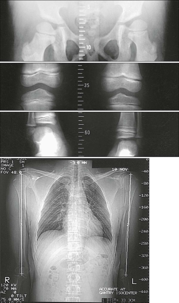
• Take CT localizer or “scout” images of the femurs and tibias.
• Place cursors over the respective hip, knee, and ankle joints, as described earlier in this chapter. To study the upper limb similarly, obtain scout images of the humerus, radius, and ulna.
• Place CT cursors over the shoulder, elbow, and wrist joints, and obtain the measurements. These measurements are displayed on the cathode ray tube (Figs. 11-8 to 11-10).
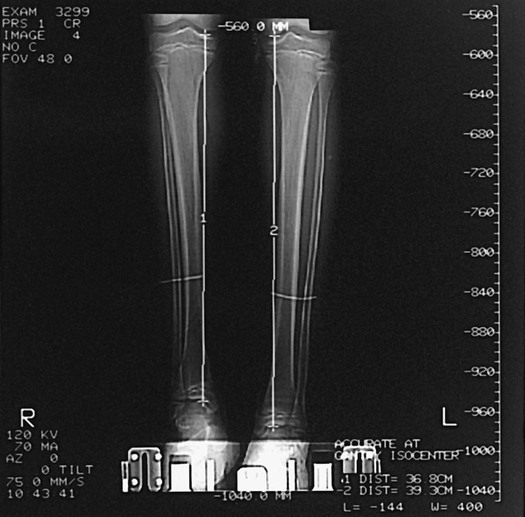
The accuracy of the CT examination depends on proper placement of the cursor. Helms and McCarthy4 found that accuracy improved when the cursors were placed three times and the values obtained were averaged. These authors also reported that CT examinations used radiation doses that were 50 to 200 times less than those used with conventional radiography, while Sabharwal and Kumar1 reported the CT dose as 80% less than that of orthoroentgenograms. CT examination requires about the same amount of time as conventional radiography, and the costs are comparable.1