Contrast Arthrography
Overview
Contrast computed tomography (CT), shoulder magnetic resonance imaging (MRI) with and without contrast, and ultrasound (US) have drastically reduced the need for radiographic contrast arthrography (Fig. 12-1). Radiography of joints is still recommended as the initial imaging for many of the joints once imaged using contrast arthrography, yet the most recent recommendations by the American College of Radiology (ACR) rank radiographic contrast arthrography from very low or not at all as an appropriate diagnostic tool. Exceptions include the following:
• Contraindications for administration of gadolinium or lack of expertise for US exams1
• Aspiration in suspected septic or inflammatory arthropathies of the shoulder1
• After knee arthroplasty as a routine follow-up or for complications2
• To rule out the hip as the referred pain source after other negative imaging3
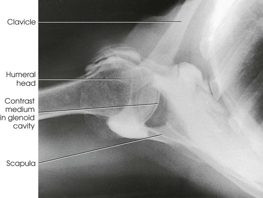
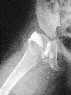
Arthrography (Greek arthron, meaning “joint”) is radiography of a joint or joints. Pneumoarthrography, opaque arthrography, and double-contrast arthrography are terms used to denote radiologic examinations of the soft tissue structures of joints (menisci, ligaments, articular cartilage, bursae) after injection of one or two contrast agents into the capsular space. A gaseous medium is used in pneumoarthrography, a water-soluble iodinated medium is used in opaque arthrography (Fig. 12-2), and a combination of gaseous and water-soluble iodinated media is used in double-contrast arthrography. Although contrast studies may be made on any encapsulated joint, the shoulder is the most frequent site of investigation. The joints discussed in this chapter—shoulder, knee, and hip—are the ones most likely to be imaged using radiographic contrast arthrography. Other joints may be imaged occasionally with arthrography. As noted previously, MRI, CT, and US are the modalities most likely to be used to demonstrate pathologies of the joints and associated soft tissues.
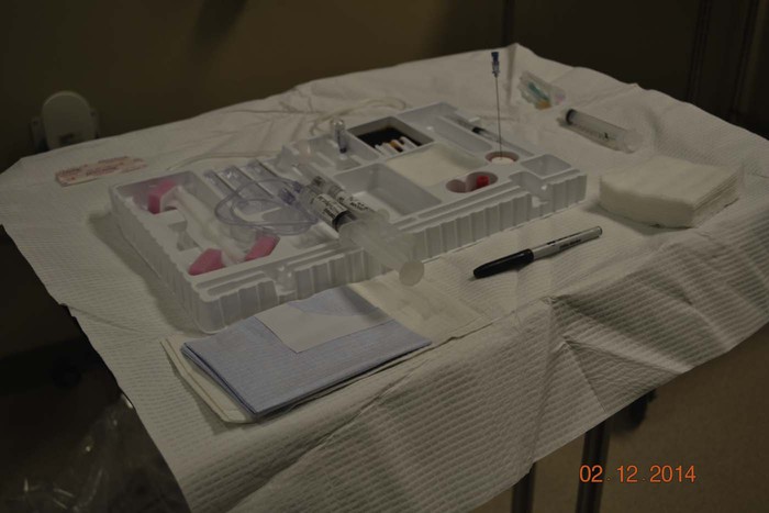
Arthrogram examinations are usually performed with a local anesthetic. The injection is made under careful aseptic conditions, usually in a combination fluoroscopic-radiographic examining room that has been carefully prepared in advance. The sterile items required, particularly the length and gauge of the needles, vary according to the part being examined. The sterile tray and the nonsterile items should be set up on a conveniently placed instrument cart or a small two-shelf table (Fig. 12-3).
SUMMARY OF PATHOLOGY
| Condition | Definition |
| Developmental dysplasia of the hip | Denotes a wide spectrum of congenital hip abnormalities, ranging from acetabular dysplasia, joint laxity, and subluxation to complete dislocation |
| Dislocation | Displacement of a bone from a joint |
| Joint capsule tear | Rupture of the joint capsule |
| Ligament tear | Rupture of the ligament |
| Meniscus tear | Rupture of the meniscus |
| Rotator cuff tear | Rupture of any muscle of the rotator cuff |
After aspirating any effusion, the radiologist injects the contrast agent or agents and manipulates the joint to ensure proper distribution of the contrast material. The examination is usually performed by fluoroscopy and spot images. Conventional radiographic images may be obtained when special images, such as an axial projection of the shoulder or an intercondyloid fossa position of the knee, are desired.
Contrast Arthrography Procedures Removed
Based on review of the most recent ACR Appropriateness Criteria® available at the time of publication of this edition, contrast arthrography of the following joint has been removed from this edition. This procedure may be reviewed in the twelfth and all previous editions.
Shoulder Arthrography
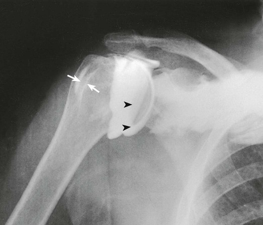
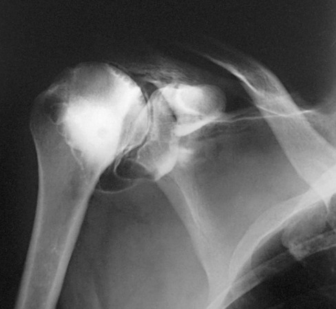
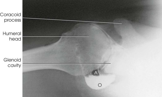
Arthrography of the shoulder is performed primarily for the evaluation of partial or complete tears in the rotator cuff or glenoid labrum, persistent pain or weakness, and frozen shoulder. A single-contrast technique (Fig. 12-4) or a double-contrast technique (Fig. 12-5) may be used.
The usual injection site is approximately  inch (1.3 cm) inferior and lateral to the coracoid process. Because the joint capsule is usually deep, use of a spinal needle is recommended.
For a single-contrast arthrogram (Fig. 12-6), approximately 10 to 12 mL of positive contrast medium is injected into the shoulder. For double-contrast examinations, approximately 3 to 4 mL of positive contrast medium and 10 to 12 mL of air are injected into the shoulder.
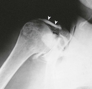
The projections most often used are the AP (internal and external rotation), 30-degree AP oblique, axillary (Figs. 12-7 and 12-8), and tangential. (See Volume 1, Chapter 5, for a description of patient and part positioning.)
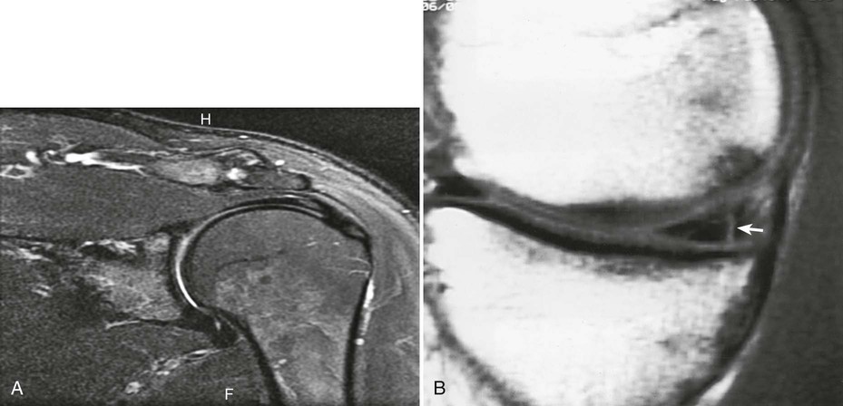
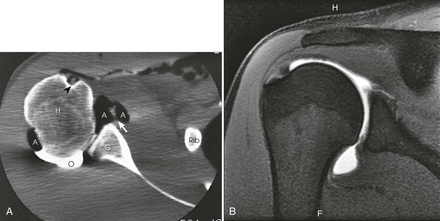
After double-contrast shoulder arthrography is performed, computed tomography (CT) may be used to examine some patients. CT images may be obtained at approximately 5-mm intervals through the shoulder joint. In shoulder arthrography, CT has been found to be sensitive and reliable in diagnosis. Radiographs and CT scans of the same patient are presented in Figs. 12-5 and 12-9. Shoulder arthrography is increasingly performed with MRI, with injection of gadolinium contrast media into the joint capsule (Fig. 12-9, B).
Contrast Arthrography of the Knee
Vertical Ray Method
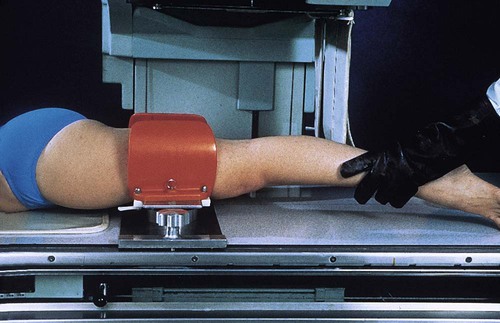
Contrast arthrography of the knee by the vertical ray method requires the use of a stress device. The following steps are taken:
• Place the limb in the frame to widen or “open up” the side of the joint space under investigation. This widening, or spreading, of the intrastructural spaces permits better distribution of the contrast material around the meniscus.
• After the contrast material is injected, place the limb into the stress device (Fig. 12-10). To delineate the medial side of the joint, place the stress device just above the knee and then laterally stress the lower leg.
• When contrast arthrograms are to be made by conventional radiography, turn the patient to the prone position, and fluoroscopically localize the centering point for each side of the joint. The mark ensures accurate centering for closely collimated studies of each side of the joint and permits multiple exposures to be made on one IR. The images obtained of each side of the joint usually consist of an AP projection and a 20-degree right and left AP oblique projection.
• Obtain the oblique position by leg rotation or by central ray angulation (Fig. 12-11).
• On completion of these studies, remove the frame and perform lateral and intercondyloid fossa projections.
NOTE: Anderson and Maslin1 recommended that tomography be used in knee arthrography. In addition, the technique frequently can be used for other contrast-filled joint capsules.
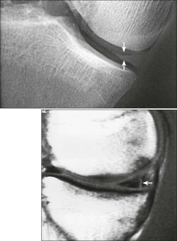
Double-Contrast Arthrography of the Knee
Horizontal Ray Method
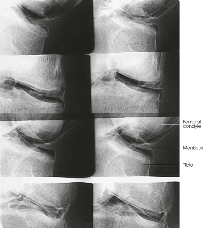
The horizontal central ray method of performing double-contrast arthrography of the knee was described first by Andrén and Wehlin2 and later by Freiberger et al.3 These investigators found that using a horizontal x-ray beam position and a comparatively small amount of each of the two contrast agents (gaseous medium and water-soluble iodinated medium) improved double-contrast delineation of the knee joint structures. With this technique, the excess of the heavy iodinated solutions drains into the dependent part of the joint, leaving only the desired thin opaque coating on the gas-enveloped uppermost part—the part under investigation.
Medial meniscus
• Adjust the patient in a semiprone position that places the posterior aspect of the medial meniscus uppermost (Fig. 12-12).

• To widen the joint space, manually stress the knee.
• Draw a line on the medial side of the knee, and direct the central ray along the line and centered to the meniscus.
• With rotation toward the supine position, turn the leg 30 degrees for each of the succeeding five exposures.
• Direct the central ray along the localization line for each exposure, ensuring that it is centered to the meniscus.
Lateral meniscus
• Adjust the patient in a semiprone position that places the posterior aspect of the lateral meniscus uppermost (Fig. 12-13).

• To widen the joint space, manually stress the knee.
• As with the medial meniscus, make six images on one IR.
• With movement toward the supine position, rotate the leg 30 degrees for each of the consecutive exposures, from the initial prone oblique position to the supine oblique position.
• Adjust the central ray angulation as required to direct it along the localization line and center it to the meniscus.
NOTE: To show the cruciate ligaments after filming of the menisci is completed,1 the patient sits with the knee flexed 90 degrees over the side of the radiographic table. A firm cotton pillow is placed under the knee and is adjusted so that some forward pressure can be applied to the leg. With the patient holding a grid IR in position, a closely collimated and slightly overexposed lateral projection is made.
Hip Arthrography
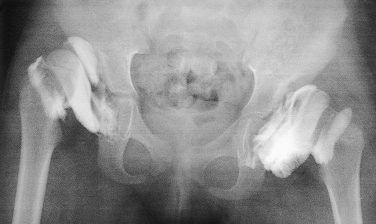
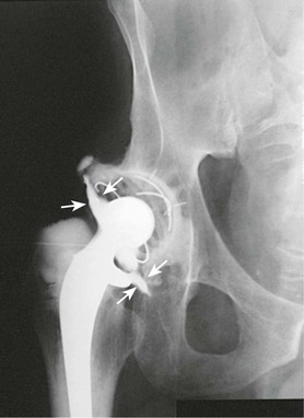
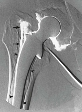
Hip arthrography is most often performed on children in a surgery suite by an orthopedic surgeon. Arthrography is used to evaluate lateral femoral head displacement and after closed reduction to ensure that there is no folding or impingement of soft tissues (see Fig. 12-2, pretreatment) (Figs. 12-14 and 12-15, post-treatment). In adults, the primary use of hip arthrography is to detect a loose hip prosthesis or to confirm the presence of infection. The cement used to fasten hip prosthesis components has barium sulfate added to make the cement and the cement-bone interface radiographically visible (Fig. 12-16). Although the addition of barium sulfate to cement is helpful in confirming proper seating of the prosthesis, it makes evaluation of the same joint by arthrography difficult.


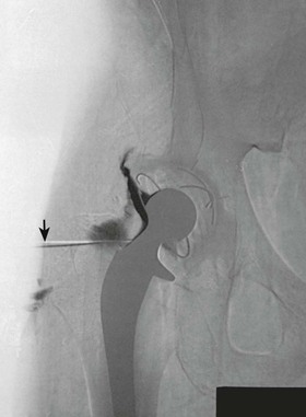
Because cement and contrast material produce the same approximate radiographic brightness, a subtraction technique is recommended—either photographic subtraction, as shown in Figs. 12-17 and 12-18, or digital subtraction, as shown in Figs. 12-19 and 12-20 (see Chapter 23). A common puncture site for hip arthrography is  inch (1.9 cm) distal to the inguinal crease and
  inch (1.9 cm) lateral to the palpated femoral pulse. A spinal needle is useful for reaching the joint capsule.

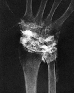
Other Joints
Essentially any joint can be evaluated by arthrography. A wrist arthrogram is included here as an example (Fig. 12-21).