Medical Gases
Storage and Supply∗
Overview
Anesthesia providers were once expected to know a great deal about the storage and supply of medical gases. In both large and small institutions, anesthesiologists often had to rely on their own knowledge and skill in this area to manage the many aspects of medical gases, from purchasing to troubleshooting.
Changes in technology and institutional organization have relieved the anesthesiologist of the majority of these responsibilities. However, this should not excuse anesthesia providers from understanding the basic facts and safety principles associated with the use of medical gases for anesthesia. Invariably, other health care providers and administrators have little knowledge regarding these systems and look to anesthesia professionals for guidance in the use and handling of these gases in the hospital or clinic setting.
With few exceptions, the only medical gases encountered by practicing anesthesiologists today are oxygen, nitrous oxide, and medical air. For safety reasons, flammable agents are rarely, if ever, used in operating rooms (ORs) today. Nitrogen is used almost exclusively to power gas-driven equipment. Helium, carbon dioxide, and premixed combinations of oxygen and helium or carbon dioxide are generally no longer used. In certain uncommon clinical situations, other gases may be used. Helium is occasionally used as an adjunct in the ventilation of patients undergoing laryngeal surgery because of its low density and flow-enhancing characteristics. Carbon dioxide is infrequently used in the management of anesthesia for repair of selected congenital heart defects. Finally, nitric oxide is currently available for use as a pulmonary vasodilator. Anesthesiologists who use these gases must be fully versed in their characteristics and safe handling. For detailed information and numerous references relating to the handling and use of these and other unusual medical gases, along with a wealth of general information about medical gas cylinders, the reader is directed to publications from the Compressed Gas Association.1,2
Medical gas manufacturers are subject to more stringent government and industry regulations and inspections than they have been in the past. This has helped markedly reduce the number of accidents related to medical gases. For these reasons, anesthesia training programs may not emphasize instruction in the various aspects of storing and using medical gases.
In addition, the recent increased concern regarding the safety of anesthetized patients has helped reduce the number of gas-related injuries. Inspired oxygen monitors with lower limit alarms provide the anesthesia practitioner with an early warning when the oxygen supply becomes inadequate or is contaminated with another gas. Mixed-gas monitoring and analysis is also becoming more common and provides the practitioner with an important way to quickly detect contaminants or unusual gas mixtures before the patient is injured. If the oxygen monitor fails, pulse oximetry can alert the anesthesiologist to problems with patient oxygenation related to inadequate oxygen supply.
Medical Gas Cylinders and their Use
Medical gases are stored either in metal cylinders or in the reservoirs of bulk gas storage and supply systems. The cylinders are almost always attached to the anesthesia gas machine. Bulk supply systems use pipelines and connections to transport medical gases from bulk storage to the anesthesia machine.
Virtually all facilities in which anesthesia is administered are equipped with central gas supply systems. Anesthesia practice is currently undergoing change in this regard, and many anesthetics are administered outside the OR, and even outside the hospital, where a central gas supply system may be unavailable. The current emphasis on providing care away from the hospital—such as in dental clinics, mobile lithotripsy units, and mobile magnetic resonance imaging facilities—will only increase the demands on the anesthesia provider to ensure a safe and continuous gas supply. E-cylinders are sometimes the only source of medical gas for anesthesia machines in these settings. If an anesthetic is being administered using only E-cylinders, then both the anesthesiologist and related support personnel must first ensure that an adequate supply of reserve cylinders is available. In addition, the amount of gas in the cylinders being used must be continually monitored, and the cylinders must be replaced before they are completely emptied. The importance of this cannot be overemphasized. Many anesthesia practitioners today have not been confronted with the possibility of running out of oxygen and having to change a tank while administering an anesthetic—but the evolving nature of anesthesia practice away from traditional facilities is likely to make this a more common occurrence. If an anesthesiologist anticipates this situation, it is imperative that the anesthesia machine be equipped with two oxygen cylinder yokes so that oxygen delivery can continue when the empty tank is changed.
Anesthesia practitioners should be familiar with two sizes of gas cylinders. The cylinder most often used by anesthesia providers is the E-cylinder, which is approximately 2 feet long and 4 inches in diameter. E-cylinders are also routinely used as portable oxygen sources, such as when a patient is transported between the OR and an intensive care unit (ICU). H-cylinders are larger, approximately 4 feet long and 9 inches in diameter, and are generally used as a source of gas for small or infrequently used pipeline systems. They may be used as an intermediate or long-term source of gas at the patient’s bedside. Almost all hospitals store H-cylinders of oxygen in bulk as a back-up source in case the pipeline oxygen fails or is depleted. H-cylinders of nitrogen are often used to power gas-driven medical equipment. H-cylinders that contain oxygen, nitrous oxide, or air have occasionally been used in ORs and are connected to the anesthesia machine via special reducing valves and hoses. Such uncommon configurations are not only potentially hazardous, they also defeat certain safeguards. Any practitioner who uses such a system must become thoroughly familiar with it and must be certain it complies with applicable regulations and guidelines.1-5
Oxygen Tanks
Oxygen (O2) has a molecular weight of 32 and a boiling point of −183° C at an atmospheric pressure of 760 mm Hg (14.7 pounds per square inch in absolute pressure [psia]). The boiling point of a gas—that is, the temperature at which it changes from liquid to gas—is related to ambient pressure in such a way that as pressure increases, so does the boiling point. However, a certain critical temperature is reached, above which it boils into its gaseous form no matter how much pressure is applied in the liquid phase. The critical temperature for oxygen is −118° C, and the critical pressure, which must be applied at this temperature to keep oxygen liquid, is 737 psia. Because room temperature is usually 20° C and therefore in excess of the critical temperature, oxygen can exist only as a gas at room temperature.
E-cylinders of oxygen are filled to approximately 1900 pounds per square inch gauge pressure (psig) at room temperature: 1 atmosphere (atm) is 760 mm Hg, which equals 0 psig or 14.7 psia. At high pressures, psig and psia are virtually the same. When full, the cylinders contain a fixed number of gas molecules, the so-called fixed mass of that gas. These gas molecules obey Boyle’s law, which states that pressure times volume equals a constant (P1V1 = P2V2), provided temperature does not change. A full E-cylinder of oxygen with an internal volume of 5 L (V1) and a pressure of 1900 psia (P1) will therefore evolve approximately 660 L (V2) of gaseous oxygen at atmospheric pressure (P2, or 14.7 psia). Thus Boyle’s law gives the approximate value:

If the oxygen tank’s pressure gauge reads 1000 psig, the tank is approximately 50% full (1000 ÷ 1900) and will evolve only 330 L (660 × 50%) of oxygen (Fig. 1-1). If such a tank were to be used at an oxygen flow rate of 6 L/min, it would empty in just under an hour (330 ÷ 6 = 55 minutes). Likewise, a full (2200 psig) H-cylinder will evolve 6900 L of oxygen at atmospheric pressure. It is important to understand these principles when oxygen tanks are being used to supply the machine or a ventilator or to transport a patient. Because oxygen exists only as a gas at room temperature, the tank’s pressure gauge can be used to determine how much gas remains in the cylinder. Clearly, if a machine is equipped with two E-cylinders of oxygen, only one should ever be open at any time to ensure that both tanks are not emptied simultaneously.
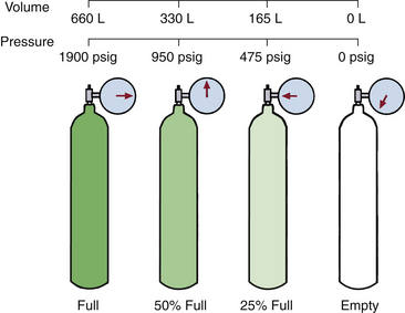
FIGURE 1-1 Oxygen remains a gas under high pressure. The pressure falls linearly as the gas flows from the cylinder; thus, in contrast to nitrous oxide, the pressure remaining always reflects the amount of gas remaining in the cylinder. (Modified from Bowie E, Huffman LM: The anesthesia machine: essentials for understanding, 1985. With permission from Datex-Ohmeda, Madison, WI.)
Nitrous Oxide Tanks
Nitrous oxide (N2O) has a molecular weight of 44 and a boiling point of −88° C at 760 mm Hg. Because it has a critical temperature of 36.5° C and critical pressure of 1054 psig, nitrous oxide can exist as a liquid at room temperature (20° C). E-cylinders of nitrous oxide are filled to 90% to 95% of their capacity with liquid nitrous oxide. Above the liquid in the tank is nitrous oxide vapor, that is, gaseous nitrous oxide. Because the liquid nitrous oxide is in equilibrium with its vapor phase, the pressure exerted by the nitrous oxide vapor is its saturated vapor pressure (SVP) at the ambient temperature.
A full E-cylinder of nitrous oxide will evolve approximately 1590 L of gaseous nitrous oxide at 1 atm (14.7 psia). As long as some liquid nitrous oxide remains in the tank and temperature remains constant (20° C), the pressure in the tank will be 745 psig, or the SVP of nitrous oxide at 20° C (Fig. 1-2). It should be clear that, unlike oxygen, the content of a tank of nitrous oxide cannot be determined from the pressure gauge. It can, however, be determined by removing the tank, weighing it, and subtracting the empty weight stamped on each tank (tare weight); the difference is the weight of the contained nitrous oxide. Avogadro’s formula for volume states that 1 g of molecular weight of any gas or vapor occupies 22.4 L at standard temperature and pressure. Thus, 44 g of nitrous oxide occupies 22.4 L at 0° C and 760 mm Hg pressure. At 20° C this volume increases to 24 L (22.4 × 293 ÷ 273); thus each gram of nitrous oxide is equivalent to 0.55 L of gas at 20° C.
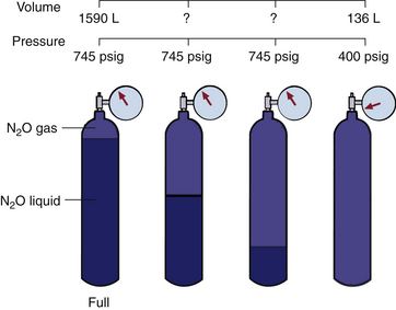
FIGURE 1-2 At ambient temperature (20° C), nitrous oxide liquefies under high pressure, and the pressure of the gas above the liquid remains constant independent of how much liquid remains in the cylinder. Only when all the liquid has evaporated does the pressure start to fall, and then it does so rapidly as the residual gas flows from the cylinder. (From Bowie E, Huffman LM: The anesthesia machine: essentials for understanding, 1985. With permission from Datex-Ohmeda, Madison, WI.)
Only when all the liquid nitrous oxide in the tank has been used up and the tank contains only gaseous nitrous oxide, can Boyle’s law be applied. In this instance, when the tank pressure (P1) is 745 psig from gas only and the internal volume (V1) of the E-cylinder is approximately 5 L, the volume (V2) of nitrous oxide gas that will be evolved at atmospheric pressure (P2) is represented by the following equation:


At this point the tank is 16% full (253 ÷ 1590). A tank showing a pressure of 400 psig at 20° C will evolve 136 L [(400 ÷ 745) × 253] of nitrous oxide gas.
While anesthesia is being administered, it is not practical to remove the nitrous oxide cylinder from the anesthesia machine and weigh it accurately enough to determine how much nitrous oxide is left. When the nitrous oxide is being used rapidly, the latent heat of vaporization causes the cylinder itself to become cold. If humidity is sufficient in the surrounding atmosphere, some moisture (or even frost) may collect on the outside surface of the cylinder over the portion that is filled with liquid nitrous oxide. The moisture line, or frost line, which may drop as the gas is used, can provide an indication of when the nitrous oxide will run out. A number of tapes and devices are available to mark the cylinders for this purpose, but their reliability has not been tested. If nitrous oxide is to be used as an anesthetic, it is best to begin with a full cylinder because the length of time the cylinder will last can be calculated. For example, a full E-cylinder of nitrous oxide used at a flow rate of 3 L/min will last about 9 hours (3 × 60 × 9 = 1620 L). When the pressure in the cylinder begins to fall, approximately 250 L are left to be evolved, and the tank will soon need to be replaced.
Characteristics of Gas Cylinders
Table 1-1 gives a list of the sizes, weights, and volumes of the common cylinders that contain various medical gases. As noted, the anesthesia provider will most often encounter oxygen and nitrous oxide in E-cylinders and a variety of gases in H-cylinders. Although other gas cylinders are found in the OR—such as those used for gas-powered equipment, laparoscopy equipment, and lasers—these are not likely to be in the domain of anesthesia personnel.
TABLE 1-1
Typical Volume and Weight of Available Contents of Medical Gas Cylinders∗
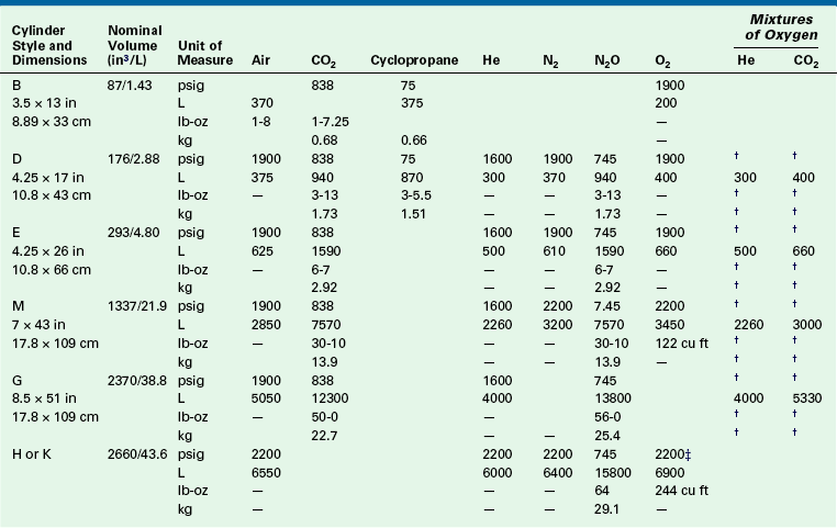
∗Computed contents are based on normal cylinder volumes at 70° F (21.1° C), rounded to no greater than 1% variance.
†The pressure and weight of mixed gases vary according to the composition of the mixture.
‡275 cu ft/7800 L cylinders at 2490 psig are available on request.
Modified from Compressed Gas Association: Characteristics and safe handling of medical gases, publication P-2, ed 7. Arlington, VA, 1989, Compressed Gas Association.
Color Coding
Table 1-2 lists the color markings used to identify medical gas cylinders. Although the internationally accepted color for oxygen is white, green is used in the United States, primarily for reasons of tradition; in addition, yellow is used to identify compressed air, which represents another exception to international standards. Anesthesiologists working in countries other than the United States should be aware of these differences. Because nitric oxide (NO) cylinders are not standardized in color and are frequently supplied as bare aluminum, it is important to check the label and not solely rely on color coding to identify a compressed gas.
TABLE 1-2
Color Marking of Compressed Gas Containers Intended for Medical Use
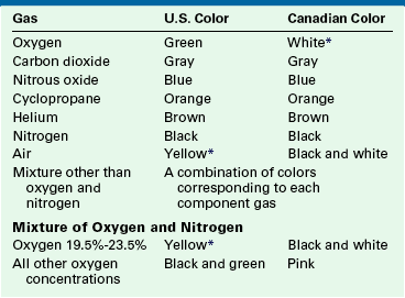
∗Historically, vacuum systems have been identified by white in the United States and yellow in Canada. Therefore it is recommended that white not be used in the United States and yellow not be used in Canada as markings to identify containers for use with any medical gas.
Modified from Compressed Gas Association: Standard color marking of compressed gas containers intended for medical use, publication C-9, ed 3. Arlington, VA, 1988, Compressed Gas Association.
Cylinder Markings
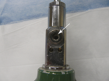
Certain codes are stamped near the neck on all medical gas cylinders. The U.S. Department of Transportation (DOT), which has extensive regulations concerning the marking and shipping of medical gas cylinders, requires a code to indicate that the cylinder was manufactured according to its specifications (Fig. 1-3). The service pressure (in psig) is stamped on each cylinder and should never be exceeded. Each cylinder is also given its own serial number and commercial designation; the final code stamped on the cylinder is usually the date of the last inspection and the inspector’s mark. Medical gas cylinders must be inspected at least once every 10 years, at which time they should also be tested for structural integrity; this is done by filling the cylinder to 1.66 times the normal service pressure. The date of this inspection is often circled with a black marker to indicate that the cylinder has been checked by the supplier (Fig. 1-4).
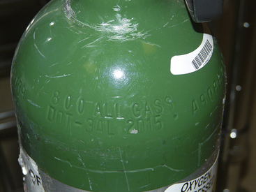
FIGURE 1-3 Some of the cylinder markings on an E-cylinder. DOT indicates that the cylinder was manufactured according to the specifications of the United States Department of Transportation (DOT); 3AL indicates the tank is aluminum. 2015 indicates the maximum filling pressure of the cylinder in pounds per square inch gauge pressure (psig), the number to the right is the cylinder serial number, and ALL GASS is the tank owner’s name.
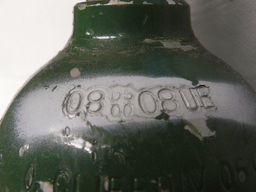
FIGURE 1-4 An E-cylinder of oxygen. The inspection date, August 2008, has been painted white to indicate the cylinder was checked at the time it was delivered to the facility. All cylinders must be checked for leaks and structural integrity with an overpressure test at least once every 10 years.
All medical gas cylinders should come from the supplier accompanied by a tag with three perforated sections, each designating a different stage of use: empty, in use, and full. The portion of the tag marked “full” should be removed when a cylinder is put into service. This is not usually critical, however, because it is generally obvious when a cylinder is in use; making use of the tag marker becomes important when an empty cylinder is removed from the machine. If the tag is not used correctly at the outset, the problem is compounded with each successive stage of the cylinder’s use, and the final result is storage of an empty cylinder as a full one. Although a discrepancy in weight may alert a user to an incorrectly labeled cylinder, this error may be easily overlooked in an emergency situation.
Pressure Relief Valves
All medical gas cylinders must incorporate a mechanism to vent the cylinder’s contents before explosion from excessive pressure.6 Explosion can result from exposure to extreme heat, such as in the event of a fire, or from accidental overfilling. These mechanisms are of three basic types—the fusible plug, frangible disk assembly, and safety relief valve—and are incorporated into the cylinder; as such, they cannot be inspected by the user. The fusible plug, made of a metal alloy with a low melting point, will melt in a fire and allow the gas to escape. With certain gases, such as oxygen or nitrous oxide, this can aggravate the fire because oxygen and nitrous oxide are both strong oxidizers. The frangible disk assembly contains a metal disk designed to break when a certain pressure is exceeded and thereby allow the gas to escape through a discharge vent. Finally, the safety relief valve is a spring-loaded mechanism that closes a discharge vent. If the pressure increases, the valve opens and remains open until the pressure decreases below the valve’s opening threshold. Some cylinders have combination devices that incorporate a fusible metal plug with one of the other two mechanisms.
Connectors
Figure 1-5 illustrates the tops of typical valves for both small (E) and large (H) cylinders. As previously mentioned, large cylinders have valve outlets that are coded and are unique to the gas content of the cylinder. The coding is based on the threads and diameter of the outlet port orifice.4 Regulators to reduce and control the pressure of the gas, also specific for each type of gas, are attached to these threaded valve ports. It is highly unsafe to use a regulator for one type of gas on a valve port of a cylinder of another type of gas.
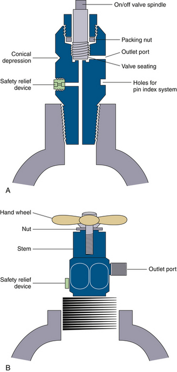
FIGURE 1-5 Typical cylinder valves. A, A small cylinder packed valve, such as would be found on an E-cylinder. Note that the female-type port is not unique to the gas type. B, A large cylinder packed valve, such as would be seen on an H-cylinder. Note that the male type of outlet port has a unique diameter and threads as a safety feature intended to help ensure correct connections. (Modified from Davis PD, Parbrook EO, Parbrook GD: Basic physics and measurement in anesthesia, ed 3. Oxford, UK, 1984, Butterworth-Heinemann.)
Small cylinders have cylindrical ports or holes in their valves to receive the yoke, either on an anesthesia machine or free standing, from which the gas will flow. A washer, usually made of Teflon, is necessary to make this connection gas tight. Care must be taken to ensure that the retaining screw that holds the cylinder in the yoke is not placed into the safety relief device instead of in its intended location in the conical depression opposite the valve port (Fig. 1-5, A). The connection between cylinder valve and yoke is made gas specific by the pin index safety system for small cylinder connections.
Gas Cylinder Safety Issues
Prevention of Incorrect Gas Cylinder Connections
In the past, cylinders containing the wrong gas—for example, nitrous oxide instead of oxygen—were sometimes connected to anesthesia gas delivery systems, with disastrous results. This led to the development of systems designed to help ensure use of the correct cylinder. Most of the gas tanks used for anesthesia are E-cylinders or other small cylinders, for which the pin index safety system was developed in 1952. The pin index system4 relies on two 5-mm stainless steel pins on the cylinder yoke connector just below the fitting for the valve outlet port. Seven different pin positions are possible depending on the type of gas in the cylinder (Fig. 1-6). The yoke connector for an oxygen cylinder, for example, has pins at positions 2 and 5 (Fig. 1-7). Pin positions for the various gases are listed in Table 1-3. These pins fit exactly into the corresponding holes in the cylinder valve (Fig. 1-8). This system provides an additional safety feature and, along with color coding, is designed to ensure that the correct gas is connected to its corresponding cylinder yoke. Obviously, connectors with either damaged or missing index pins are unsafe and should not be used under any circumstances. Because a pin can easily be lost or damaged when a cylinder is handled roughly, the person changing the cylinder must make certain that both pins are intact.
TABLE 1-3
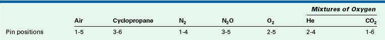
The pin index system relies on two 5-mm stainless steel pins on the cylinder yoke connector just below the fitting for the valve outlet port. Seven different pin positions are possible depending on the type of gas in the cylinder (the seventh pin position is for a gas not used in the United States). See Figures 1-6 and 1-7 for pin locations.
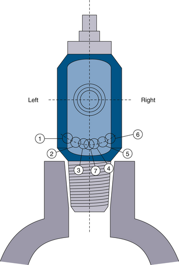
FIGURE 1-6 Pin index safety system pin location is shown, looking at the placement of holes in the tank. Pins are placed precisely complementary in the tank yoke. Two pins are used to identify each type of gas. Pin configurations are listed in Table 1-3.
Securing Cylinders Against Breakage
Gas cylinders should always be secured when placed in an upright position. If left freestanding, a cylinder can easily fall over in such a way that it would fracture at the neck (Fig. 1-9). The cylinder’s highly pressurized gas would be suddenly released, and the cylinder would become an unguided missile of tremendous force; in fact, the cylinder could generate enough force to penetrate a cinder-block wall several feet thick. The potential danger of such an occurrence is obvious. Therefore, all gas cylinders must be secured when they are upright. If that is not possible, the cylinder can be laid on its side. Individual E-cylinders can be placed in a broad-based wheeled carriage for support when in use.
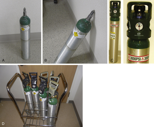
FIGURE 1-9 A, Gas cylinders must never be left standing upright and unsecured. They are vulnerable to being knocked over easily, such as by opening a door. Cylinders that fall directly to the floor, and especially cylinders that fall so that the top hits a wall (B), are at great risk for breaking at the cylinder neck. This creates a dangerous “unguided missile,” in which the high-pressure gas escapes out the narrow neck and rockets the cylinder forward with enough force to penetrate a brick wall. C, Oxygen cylinders are now available with a maximum pressure of 300 psi and a capacity of 1000 L of oxygen. These would present an even greater hazard if ruptured. D, If upright, individual cylinders should be secured in some type of holder, such as a rolling stand for E-sized cylinders.
Transfilling
Anesthesia personnel should never attempt to refill small cylinders from larger ones. Even if gas-tight connections were possible, the risk of explosion from the heat of compression in the small cylinder would still be serious. In addition, there is always the possibility that the wrong gas would be placed in the cylinder. The practice of transfilling is also forbidden. Medical gases must be obtained only from a reputable commercial supplier.
Cylinder Hazards
A study of 14,500 medical gas cylinders consecutively delivered from supposedly reputable suppliers found 120 (0.83%) with potentially dangerous irregularities.7 Forty cylinders were delivered either empty or partially filled, 3 were found to be dangerously overfilled to near-bursting pressures, and 6 cylinders of compressed air were found to be contaminated with volatile hydrocarbons. Thirty cylinders were unlabeled, and the labels of many others were illegible, having been painted over. Another 4 cylinders were incorrectly color coded, 5 large cylinders were fitted with incorrect valve outlet ports (which is especially dangerous because an oxygen valve on an air cylinder enables air to be fed into an oxygen outlet), 14 valve assemblies were found to be loose, and 4 valve assemblies were inoperable. On a large number of cylinders, the current inspection date was either absent or had been painted over so as to be illegible. Numerous examples were cited of cylinders being improperly stored or secured. The results of this study serve to remind anesthesia practitioners of the danger of assuming that gas supplies are perfectly safe. All facilities should have an established system to ensure that each cylinder of medical gas is inspected and tested upon delivery to the facility.
Guidelines for use of Medical Gas Cylinders
Numerous rules govern the safe handling of cylinders that contain medical gases.1,2 Summarized below are practical points that anesthesia practitioners must consider on a routine basis.
Supply
As noted, medical gases should be purchased only from a reputable commercial supplier. Outside metropolitan areas, the only supplier of any type of compressed gas may be the local welding company. Purchasing medical gases from such a source can be appropriate once it has been established that this supplier meets all safety requirements and standards for the manufacture and supply of medical gases. Such verification should be incorporated into the system to promote maximum safety.
Storage
Specific regulations and standards govern the storage of medical gas cylinders.2,3 For example, full cylinders and empty cylinders must be stored separately, each in its own “tank room” if possible. Small cylinders should be placed in nonflammable racks, and large cylinders should be chained to a wall. At least one anesthesiologist in each facility should be aware of these requirements and how they are being implemented. Anesthesia caregivers should also assume responsibility for all aspects of medical gas supplies.
Transport and Installation
Medical gas cylinders must be handled with care. As previously mentioned, a broken cylinder can have serious consequences, as can valve assemblies damaged by rough handling. Cylinders should undergo a final inspection just before they are used. If questions arise concerning the safety or content of a cylinder, it should not be used; instead, an investigation should be undertaken before returning the cylinder to the supplier. Before a small E-cylinder is installed in the hanger yoke, the plastic wrapping surrounding the cylinder valve outlet must be completely removed. If this is not done, the plastic wrapper will prevent the gas from entering the inlet in the hanger yoke. All cylinders should be opened slightly, or “cracked,” immediately before installation to clean any residual oil, grease, or debris from the valve outlet port that would otherwise be released into the anesthetizing apparatus. Furthermore, cylinders should always be opened slowly to prevent dramatic heating of the suddenly pressurized piping. If an abnormal odor is detected when the cylinder is opened, gas should be collected from the tank and analyzed by gas chromatography to detect hydrocarbon contamination.8 Once a problem is confirmed, the cylinder in question should be sequestered, not returned to the supplier, and the appropriate local and federal authorities contacted.
Connections between gas cylinders and anesthesia machines must be tight. Figure 1-10 illustrates the proper method for balancing the tank when securing it to or removing it from the yoke. Washers are necessary for small cylinder yokes and occasionally need replacement; the old washer must be removed before placing a new washer. Having two washers in place simultaneously will create a leak and may defeat the pin index system. If a hissing noise is heard when a cylinder is opened, a leak is present. Tightness can always be checked by dripping soapy water onto the connection and inspecting it for bubbles. A connection should never be overtightened in an attempt to compensate for a leak; doing so may damage or even crack the cylinder valve. As in all aspects of anesthesia practice, brute force is almost never appropriate.
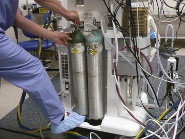
FIGURE 1-10 Proper method for attaching an E-cylinder to the yoke of an anesthesia machine. The tank is first supported on the anesthesiologist’s foot while the holes on the tank are aligned with the pins in the yoke. The tank is then slid into place on the yoke, and the T-handle is tightened to make a gas-tight seal.
Once a new cylinder is in place, the pressure must be checked on the applicable gauge. Correct pressures for full cylinders are listed in Table 1-1. Overpressurized cylinders are dangerous and must be removed at once and reported to the supplier.
Medical Gas Pipeline Systems
Medical gas pipeline systems consist of three main components: 1) a central supply of gas, 2) pipelines to transport gases to points of use, and 3) connectors at these points that connect to the equipment that delivers the medical gas. Anesthesia caregivers are primarily concerned with piped oxygen and nitrous oxide; however, ORs may have two other medical gas supply pipelines: one for compressed air and another for nitrogen to power gas-driven equipment.
Detailed standards and guidelines exist for the use of medical gas delivery systems. In North America, these are published by the American National Standards Institute (ANSI), the American Society of Mechanical Engineers (ASME), the Compressed Gas Association (CGA), the National Fire Protection Association (NFPA), the Canadian Standards Association (CSA), and the American Hospital Association (AHA).9 In the United States, a hospital must meet the NFPA standards to be accredited by The Joint Commission (TJC) and often to obtain insurance coverage. The construction of a medical facility is governed by standards, and the procedures required for operating a medical gas system must be followed by the plant engineering and maintenance departments. Problems in the construction of gas pipelines have led to anesthesia deaths; anesthesia providers should therefore be aware of these standards and the gas delivery system at their facility.10
Medical Gas Central Supply Systems
The central supply (bulk storage) system is the source of medical gases distributed throughout the pipeline system. For oxygen, the central supply can be a series of standard cylinders connected by a manifold system or, for larger installations, pressure vessels of liquid oxygen with accompanying vaporizers. For medical air, the supply can be cylinders of compressed air, cylinders of oxygen and nitrogen with the gases mixed by a regulator, or air compressors. In general, for nitrous oxide or nitrogen, a series of cylinders, or liquid Dewar tanks, with a manifold system is used.
Oxygen
Central supply systems that carry oxygen are both the most common and the most important supply systems; as such, they have received considerable attention. Standards for bulk systems that involve the storage of oxygen as a liquid are contained in NFPA Publication 55.11 Oxygen systems are extensively covered in NFPA Publication 9912 and in the CSA Standard Z305.1.13
Very small systems have a total storage capacity of less than 2000 cubic feet (cu ft) of gas (a single H-cylinder of oxygen contains 244 cu ft, or 6900 L) and have additional standards when based in nonhospital facilities. Systems in very small hospitals may store oxygen in a series of standard H-cylinders connected by a manifold or high-pressure header system. These systems typically do not have reserve supplies. In Figures 1-11 and 1-12, note that there are two banks of cylinders; all central supply systems for medical gases must be present in duplicate, with two identical sources able to provide the needed medical gas interchangeably. These are often referred to as the primary and secondary supplies (not to be confused with the entirely separate reserve system).
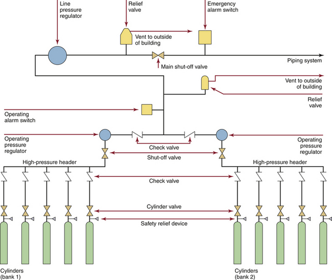
FIGURE 1-11 Typical cylinder (H size) supply system, as would be seen in a small hospital or a freestanding facility. There is no reserve supply. (From CSA Standard Z305.1-1975, Nonflammable medical-gas piping systems. Toronto, 1975, Canadian Standards Association.)
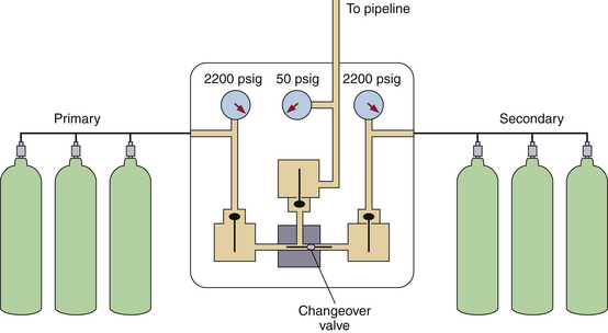
FIGURE 1-12 A simplified version of Figure 1-11. The oxygen is supplied in H-cylinders from both a primary and a secondary supply. The tanks are connected by a manifold; when the tanks are full, the pressure is 2200 psig. A changeover valve automatically switches to the secondary supply once the primary supply has been exhausted. A reducing valve decreases the pressure to 50 psig before the oxygen enters the hospital pipeline. (Modified from Davis PD, Parbrook EO, Parbrook GD: Basic physics and measurement in anesthesia, ed 3. Oxford, UK, 1984, Butterworth Heinemann.)
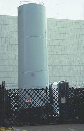
The larger the oxygen demand of the facility, the more complex the supply system. Most hospitals store their bulk oxygen in liquid form (Fig. 1-13), which enables the hospital to maintain a large reservoir of oxygen in a relatively small space. One cubic foot of oxygen stored at a temperature of −297° F (−183° C) expands to 860 cu ft of oxygen at 70° F (21° C).14 Because 1 cu ft is equal to 28.3 L, this amount of liquid oxygen provides 24,338 L at room temperature and pressure, the equivalent of 3.5 H-cylinders of oxygen.
Liquid oxygen is stored in a special container and kept under pressure. This container has an inner and outer layer separated by layers of insulation and a near vacuum. This construction is similar to that of a thermos bottle and keeps the liquid oxygen cold by inhibiting the entry of external heat (Fig. 1-14).
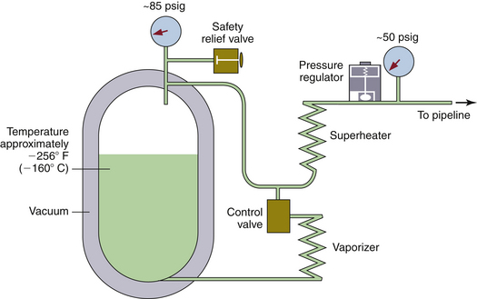
FIGURE 1-14 Diagram of a liquid oxygen supply system. The vessel resembles a giant vacuum bottle. The liquid oxygen is at approximately −256° F (−160° C). Pressure inside the vessel is maintained at approximately 85 psig. When oxygen is used from the top of the vessel, it first passes through a superheater and then through the pressure regulator to keep the pipeline pressure at 50 psig. During times of rapid use, the temperature in the tank may fall, along with the vapor pressure. The control valve causes liquid oxygen to pass through the vaporizer, which adds heat and thus maintains the pressure in the tank. (Modified from Davis PD, Parbrook EO, Parbrook GD: Basic physics and measurement in anesthesia, ed 3. Oxford, UK, 1984, Butterworth-Heinemann.)
Liquid oxygen systems must be in constant use to be cost effective. If the system goes unused for a period of time, the pressure increases as some of the liquid oxygen boils. The oxygen is then vented to the atmosphere. The liquid oxygen system contains vaporizers that heat the liquid and convert it to a gas before it is piped into the hospital. Environmental and mechanical heat sources can be used to aid in vaporization.
Liquid oxygen can be extremely hazardous, and fires are an ever-present danger. In addition, personnel can receive severe burns if they come in contact with liquid oxygen or an uninsulated pipe carrying liquid oxygen.
Small hospitals typically require central supply systems that store oxygen in replaceable liquid oxygen cylinders and a reserve of oxygen stored in high-pressure H-cylinders. The reserve system is automatically activated when the main supply, with its component primary and secondary storage, fails or is depleted (Fig. 1-15). Hospitals of average size may store liquid oxygen in bulk pressure vessels rather than in liquid oxygen cylinders. The storage vessel is filled from a liquid oxygen supply truck through a cryogenic hose designed to function at extremely low temperatures. In such a system, the size of the reserve system depends on the rate of oxygen use because the reserve must constitute at least an average supply for 1 day, but preferably 2 to 3 days. This supply may be stored in a series of high-pressure H-cylinders. However, large hospitals are required to have a second liquid oxygen storage vessel as the reserve system because of the impracticality of storing and connecting enough cylinders to provide an average day’s reserve supply of oxygen (Fig. 1-16).
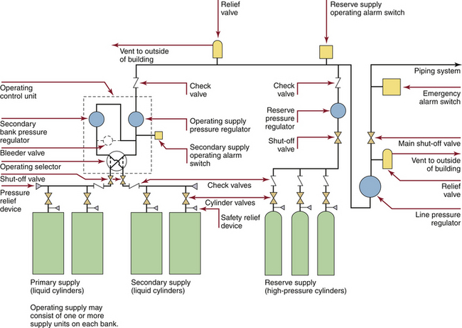
FIGURE 1-15 Typical cryogenic cylinder supply system for liquid oxygen with a high-pressure cylinder reserve supply, as would be seen in a small hospital. The redundant primary and secondary liquid cylinders are intended to be the continuous oxygen source; there is an automatic switchover to the other bank when one is depleted and ready for replacement. The reserve supply is automatically activated when both banks of cylinders are depleted or fail. (From CSA Standard Z305.1–92, Nonflammable medical gas piping systems. Toronto, 1992, Canadian Standards Association.)
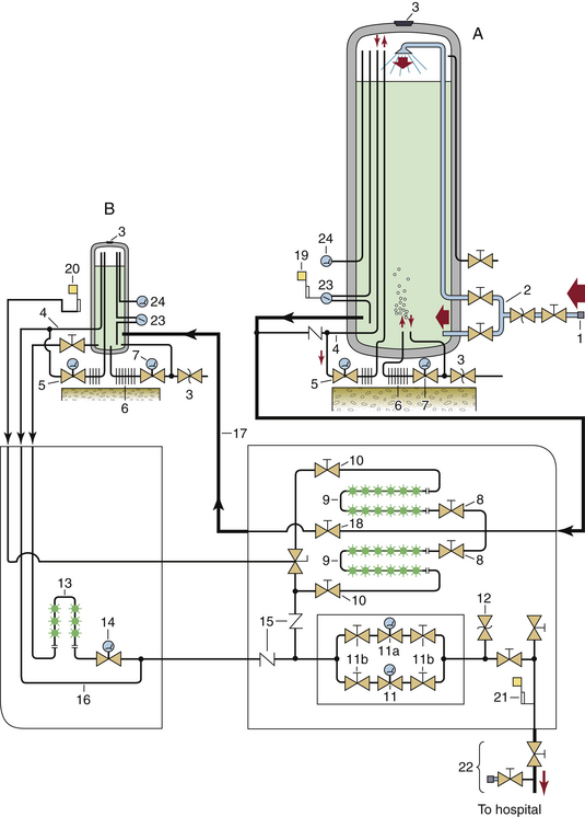
FIGURE 1-16 Typical bulk supply system for oxygen, as would be seen in a large hospital. Very large hospitals may require more than one system of this magnitude. A, Main liquid oxygen reservoir. B, reserve liquid oxygen reservoir. 1, Connection to supply vehicle; 2, top and bottom fill lines; 3, reservoir pressure relief valves; 4, “economizer” circuit; 5, gas regulator in pressure-building circuit; 6, pressure-building vaporizer; 7, liquid regulator in pressure-building circuit; 8, cryogenic liquid-control valves; 9, liquid vaporizers; 10, downstream valves for isolation of vaporizers; 11, primary line pressure regulator; 11a, secondary line pressure regulator; 11b, valves to isolate regulators for repair; 12, pressure relief valve for main pipeline; 13, reserve system liquid vaporizer; 14, reserve system line pressure regulator; 15, gas flow check valves; 16, reserve system “economizer” line; 17, reserve system fill line; 18, valve controlling flow to reserve system from main cylinder; 19, low liquid level alarm; 20, reserve in use alarm; 21, main line pressure alarm; 22, main shut-off valve and T-fitting; 23, liquid level indicators; 24, vapor or “head” pressure gauges. In normal operation, liquid oxygen flows from the lower left of the main vessel (A) via a cryogenic pipe through valves (8) and to the vaporizer (9), where the liquid becomes gaseous oxygen. It then flows through pressure regulators (11) and hence into the supply pipeline to the hospital. (From Bancroft ML, du Moulin GC, Hedley-Whyte J: Hazards of bulk oxygen delivery systems. Anesthesiology 1980;52:504-510.)
Built into all these central supply systems for oxygen are a variety of mandatory safety devices. Pressure relief valves are designed to open if pressure in the system exceeds the normal level by 50%. This prevents the rupture of vessels or pipes from the excessive pressure generated by a frozen valve or a malfunctioning pressure regulator. Alarm systems indicate when the supply in the main storage vessel is low and when the reserve supply has been accessed. An oxygen alarm should activate a rehearsed protocol within the hospital that results in contact with the oxygen supplier and subsequent verification that an oxygen delivery is on the way.15 Pressure alarms built into the main supply line sound when the line pressure varies by 20% in either direction from the normal operating pressure of approximately 55 psig. Pressure alarms should also be located in various areas in the pipeline to detect oxygen supply problems beyond the main connection (Fig. 1-17).
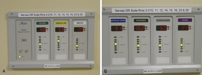
FIGURE 1-17 A, Bank of pressure gauges that monitor the gases in one zone of the operating room. These gauges are for oxygen, air, and vacuum. Note that the rooms being monitored are identified on the top of the panel. B, A second gas monitoring panel for N2O, nitrogen, CO2, and waste gases. Note that colored lights indicate whether the line pressures are in the normal range; alarms are triggered for high or low pressures.
All these alarm systems must sound in two different locations: the hospital maintenance or plant engineering department and an area occupied 24 hours a day, such as the telephone switchboard. These alarms should be periodically tested as part of a regular maintenance program because failure of such alarms has led to crisis situations. Testing the various alarms can be difficult but is possible if the system is properly designed.
Another critical safety feature is the T-fitting located at the point where the central supply system joins the hospital piping system. This fitting allows delivery of an emergency supply of oxygen from a mobile source in the event of extended failure, extensive repair, or modification of the hospital’s central supply.
The location and housing of oxygen central supply systems are governed by strict standards.11 A bulk oxygen storage unit should be located away from public areas and flammable materials.
Oxygen Concentrators
The use of oxygen concentrators to deliver oxygen to the anesthesia circuit has gained attention recently. Oxygen is generated by the selective adsorption of the components of air with molecular sieve technology. These sieves consist of rigid structures of silica and aluminum, with additional calcium or sodium as cations.16 Air is forced through the sieves under pressure, and oxygen and nitrogen are generated. The oxygen is then used clinically, and the nitrogen is vented to the atmosphere. The maximum oxygen concentration produced by concentrators is approximately 90% to 96%, with the balance made up mostly of argon.17,18
Oxygen concentrators are commonly used in remote locations and developing countries, but in some cases they have been configured to supplement a hospital’s existing liquid oxygen system as a reserve or a secondary supply.17 Oxygen concentration may vary with gas flow, and concentrators are most effective at delivering oxygen at flows of less than 4 L/min to anesthesia machines.18 Accumulation of argon may occur, however, in low-flow conditions, so the use of an oxygen monitor is essential.19 As the current emphasis on cost cutting in medical care continues, along with cost increases of supplied liquid and gaseous oxygen, oxygen concentrators are likely to come into wider use.
Medical Air
The central supply of medical air can come from three sources: 1) cylinders of compressed air that have been cleaned to medical quality by filtration distillation; 2) a proportioning system (relatively uncommon) that receives oxygen and nitrogen from central sources, mixes them in a proportion of 21% oxygen to 79% nitrogen, and delivers this mixture to the medical air pipeline (these systems usually have compressed air cylinders or an air compressor as a reserve system); and 3) air compressors (Fig. 1-18), the most common source of medical air in hospitals. The compressor works by compressing ambient air and then delivering the pressurized air to a reservoir or holding tank.14 The medical air is then fed to the pressure regulator and travels from there to the hospital piping system.
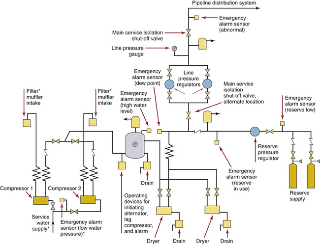
FIGURE 1-18 A typical duplex medical air compressor system. Compressors (lower left) draw in ambient air and send high-pressure air to a holding tank. It is critical that these air intakes not be located near any source of air pollution, such as a garage or the exhaust from the facility’s vacuum system. The air from the holding tank is dried and filtered on its way to pressure regulators, which deliver gas at about 55 psig into the pipeline system. ∗Where required. (From Standard Z305.1–92, Nonflammable medical gas piping systems. Toronto, 1992, Canadian Standards Association.)
Air compressor systems are subject to rigorous standards.12,13 As with other systems (i.e., vacuum or electrical generators), redundancy is important. Duplicate compressors are necessary, each with the capacity to meet the entire hospital’s medical air needs if the other fails. The system must be used only for the medical air pipeline and not for the purpose of powering equipment. If air is to be used for powering equipment, a separate instrument air system must be installed. (The requirements for this system are specified in NFPA-99.) The compression pumps must not add contaminants to the gas, and the air intake must be located away from any street or other exhaust. It is particularly important that the pumps be located away from the hospital’s vacuum system exhaust. The air must first be thoroughly dried to remove water vapor and then filtered to remove dirt, oil, and other contaminants. The condensed water is then properly disposed of to eliminate potential breeding grounds for bacteria, such as those that cause Legionnaire’s disease. Valves, pressure regulators, and alarms analogous to those in oxygen supply systems are needed. In addition, the piping should not be exposed to subfreezing temperatures.
Nitrous Oxide
Specific standards exist for nitrous oxide systems, and certain portions of the more general standards of the NFPA and CSA are applicable as well.20 A nitrous oxide central supply system may be warranted, depending on the expected daily use of the gas. If demand is sufficient, such a system could be cost effective compared with attaching small cylinders to each anesthesia machine. Even though anesthesiologists are the only people who use the nitrous oxide system, they must delegate the responsibility for the operation and maintenance of the central nitrous oxide system to other hospital personnel.
Nitrous oxide central supply systems are usually of the cylinder-manifold type, as shown in Figure 1-11. Again, it is necessary to have two separate banks of cylinders with an automatic crossover; however, large institutions may need a bulk liquid storage system similar to the one used for oxygen, shown in Figure 1-16. In this case, the storage of liquid nitrous oxide requires an insulated container similar to that used for liquid oxygen.
Helium
Helium is commonly supplied in an E-size cylinder with a flowmeter that delivers it into the fresh-gas flow, but H-size cylinders are also used. Anesthesia machines are available that incorporate a helium flowmeter on the manifold, usually in place of medical air (see Fig. 1-18, A). Although this design incorporates some of the anesthesia machine’s safety features, care must be taken to avoid delivering hypoxic gas mixtures. On new machines, helium tanks are supplied premixed with oxygen as a 3:1 He/O2 mixture. This prevents the risk of hypoxia that occurs when 100% helium tanks are used on the machine.
Nitric Oxide
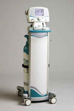
Inhaled nitric oxide is approved and regulated by the U.S. Food and Drug Administration as a pharmaceutical product, not as a medical gas. It is provided as 800 ppm nitric oxide diluted in nitrogen and available in D cylinders (353 L at 2000 psig) or the larger 88 cylinders (1963 L at 2000 psig). The selected concentration of inhaled nitric oxide is delivered into the inspiratory limb of the breathing system. A monitoring device to measure the concentrations of oxygen, nitric oxide, and nitrogen dioxide (a toxic byproduct) is placed downstream of the nitric oxide inlet. Ikaria, Inc. (Hampton, NJ) produces the INOmax DS delivery system, which electronically controls the amount of nitric oxide injected into the circuit, monitors delivered concentrations, and adjusts nitric oxide to maintain a constant concentration despite variations in fresh gas flow (Fig. 1-19).
Nitrogen
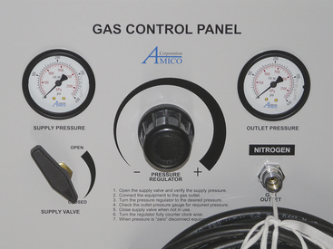
Even though a nitrogen central supply system is designed to supply gas only for powering OR equipment, it is still subject to the same standards outlined above. Nitrogen supply systems are frequently smaller than those for nitrous oxide but are of essentially the same design, in which a series of H-cylinders are connected by a manifold (pressure header) system that feeds a pressure regulator. A typical nitrogen control panel is illustrated in Figure 1-20. Again, because this system services the OR, it is important to delegate responsibility for maintenance. Although relatively uncommon, some systems are designed to mix central nitrogen with oxygen to create medical air. It is also possible to store nitrogen as a liquid for a centrally supplied system.
Central Vacuum Systems
Although not a source of medical gas, the central vacuum system is no less important and demands the same attention to detail as a medical gas system. Inadequate or failed suction can be disastrous in the face of a surgical or anesthetic crisis.
Certain standards exist for the central vacuum source and vacuum piping system; the Canadian standards are considered the most complete and current.13 Larger ORs must have enough suction to remove 99 L/min of air. Factors such as normal wall suction (−7 psig), total flow of the system, and the length of the longest run of pipe must be considered to maintain adequate suction. Two independent vacuum pumps must be present, each one capable of handling the peak load alone. An automatic switching device distributes the load under normal conditions and automatically shifts if one unit fails. Emergency power connections are essential, and the pumps must be located away from oxygen and nitrous oxide storage. There must be traps to collect and safely dispose of any solid or liquid contaminants introduced into the system, and the system piping must not be exposed to low temperatures to prevent condensation. The type and location of the vacuum system exhaust is specified and must not be near the intake for the medical air compressor.
Medical Gas Pipelines
Medical gas must travel through a pipeline to reach its designated point of use. The potential for serious injury to a patient from a medical gas pipeline mishap has led to the development of detailed standards.12,13
Planning
In any new construction, physicians must provide architects and engineers with the number and desired locations of any gas outlets. Anesthesiologists need to decide whether they want one or two sets of outlets for anesthesia gases in each OR and whether they want wall and/or ceiling-mounted distribution of the gases. Representatives from all the departments that will use the system should be involved in planning the location of the outlets. A basic layout for a portion of a piping system is illustrated in Figure 1-21. Extensive planning is necessary for each separate medical gas pipeline, and anesthesiologists must be aware of all appropriate requirements. For example, each anesthetizing location must have a separate shut-off valve (Fig. 1-22), and other areas such as the postanesthesia care unit (PACU) require zone shut-off valves.
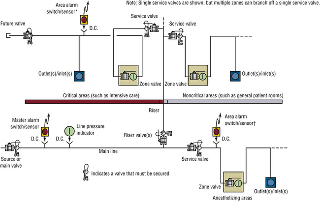
FIGURE 1-21 A representative portion of the pipeline system for oxygen in a hospital. Note that separate similar designs are needed for the other medical gases. The schematic is representational, demonstrating a possible arrangement of required components. It is not intended to imply a method, materials of construction, or more than one of many possible and equally compliant arrangements. Alternative arrangements are permitted. ∗Area alarms are required in critical care locations (e.g., intensive care units, coronary care units, angiography laboratories, cardiac catheterization laboratories, postanesthesia recovery rooms, and emergency rooms) and anesthetizing locations (e.g., operating rooms and delivery rooms). †Locations for switches/sensors are not affected by the presence of service or inline valves. (From NFPA 99-2012. Health care facilities. Copyright 2011, National Fire Protection Association. Quincy, MA, 02269.)
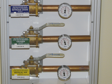
FIGURE 1-22 Typical shut-off valves for the gases supplied in operating rooms (ORs). Each gas must have its own shut-off valve, and a separate set of valves must be present for each OR.
Detailed standards must be followed with respect to the specific type of pipe used, typically seamless copper tubing, as well as the cleaning, soldering, and supporting of the pipe within the walls.8,12,13 In addition, pipelines must be protected, such as by enclosure in conduits, especially when they run underground. Pipes located inside risers and walls must be labeled in a specific way and at given intervals.
Once drafted, the plans must be examined to verify that all standards have been met. Given the fact that the construction of medical gas pipelines is relatively uncommon, it is possible that a given engineering, architectural, or building firm has never constructed one before. Any changes made in the plans should be recorded in the as-built drawings to enable hospital personnel to discern the exact location of the pipes if problems arise.
Additions to Existing Systems
Even more difficult than planning a new medical gas pipeline system is adding to an existing system. In addition to all the planning outlined above, the interaction between the old facility and the new one must be considered. The central supply system may need to be expanded to include new pipeline systems, which may necessitate the difficult task of shutting down the existing pipeline system. Extreme precision is required for such an operation, and procedural standards exist both for modifying or adding to existing systems.13
Installation and Testing
Installation of a pipeline should be overseen by a representative from the medical facility, and the testing should actively involve several individuals who will use the system. Prior to installation, the copper tubing used for the medical gas pipeline must be clean and free of contamination. The lengths of pipe must be stored with both ends sealed with rubber or plastic caps to prevent contamination. After the pipelines have been installed, but before the outlet valves are installed at each gas outlet location, high-pressure gas must be used to blow the pipeline free of any particulate matter.
The pipeline system involves pressure regulators that function to maintain normal outlet pressure (e.g., 55 psig for oxygen). Also, there must be pressure relief devices that automatically vent the gas if the pressure increases by 50% above the normal operating pressure. High- and low-pressure alarms and shut-off valves are required at various locations throughout the system. The locations of all these should be marked on a map of the institution.
The pipeline terminates at various locations within the hospital. A connector is installed at these termination points to allow the interface of various pieces of medical equipment, such as the anesthesia machine or ventilator. The connectors installed at each outlet of the pipeline are subject to detailed requirements.12,13 Two basic types of connectors are used: one is the quick coupler, which is made by several manufacturers and allows rapid connection and disconnection of fittings and hoses (Figs. 1-23 and 1-24). The other is a noninterchangeable thread system called the diameter index safety system (Fig. 1-25).5 Both systems have gas-specific fittings to prevent incorrect connections. Improper use of a gas outlet or use of an incorrect fitting essentially defeats the purpose of the built-in safeguards of the system. Accordingly, the station outlets must have back-up automatic shut-off valves in case the quick coupler is damaged or removed. All outlets, hoses, and quick couplers should be properly labeled and color coded.
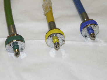
FIGURE 1-23 Common types of quick couplers used in hospitals. Note that each has a specific pin configuration for the individual gas. The quick coupler and the attached hose should be color coded for the specific gas.
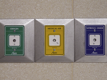
FIGURE 1-24 Wall connections for oxygen, air, and nitrous oxide in a safety-keyed quick-connect system. The GE Healthcare (Waukesha, WI) quick-connect system is shown, in which each gas is assigned two specific pins with corresponding inlet holes within the circumference of the circle. In this manner, the connection is made gas specific.
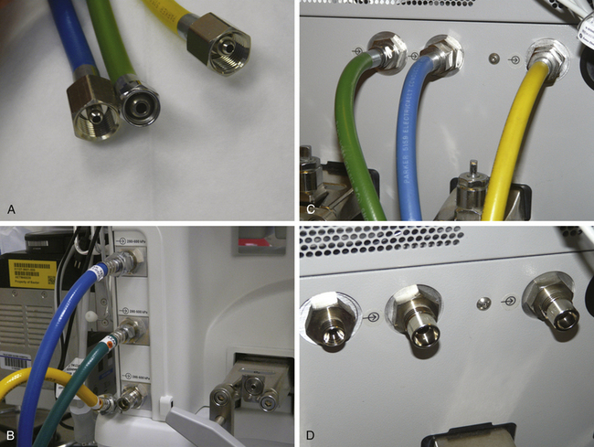
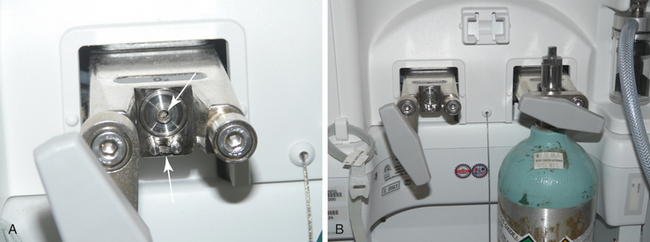
FIGURE 1-25 A, Examples of hoses with the diameter index safety system (DISS). These are threaded connections in which the diameters of the threads are specific for each of the gases. B and C, Connections made to DISS fittings on the anesthesia machine. D, DISS fittings on an anesthesia machine.
Gas outlets in the OR may be located in either the wall or the ceiling. If the gas hoses are run along the floor, they must be made of noncompressible materials to prevent obstruction in case the hose is run over by a piece of heavy equipment. Outlets may be suspended from the ceiling in columns or as freestanding hose drops (Fig. 1-26), or they may be integrated into a multiservice gas boom (Fig. 1-27). These gas booms can be configured with all the anesthetic gases as well as vacuum systems, electrical outlets, monitor connections, and even data and telephone lines. They can be rotated to several different positions and can be raised or lowered as necessary.
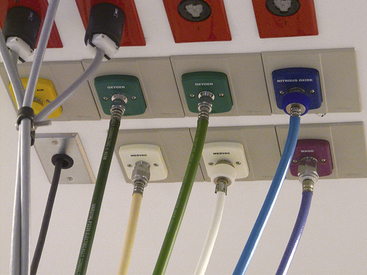
FIGURE 1-26 Freestanding ceiling hose drops in an operating room. Note the proximal ends of the hoses (nearest to the ceiling) have diameter index safety system connections. The distal ends (nearest to the anesthesia machine) have quick-coupler connections (see Fig. 1-23).
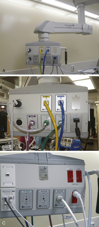
FIGURE 1-27 A to C, The distribution head for an articulating multiservice gas boom. Compressed gases, vacuum, waste anesthesia gas, computer/Internet, and electrical connections can all be integrated at one location. The articulated arm can be raised, lowered, or rotated in a wide arc.
Testing of the pipeline begins after the couplers have been installed. Before the walls are closed, the pipeline is subjected to 150 psig, and each joint is examined for leaks. The system then undergoes a 24-hour standing pressure test, in which the system is filled with gas to at least 150 psig, disconnected from the gas source, and closed. If the pressure is the same after 24 hours, no leaks are present. Cross-connection testing involves pressurizing each pipeline system separately with test gas and verifying that only the outlets of that particular system—for example, compressed air—are pressurized. This is particularly important when additions or modifications are made to existing pipeline systems.
After the correct connections have been verified, each pipeline is connected to its own central supply of gas, and the pipelines are purged with their own gases. The content of gas from every station outlet must then be analyzed. An oxygen analyzer can be used for the oxygen (100%) and medical air (21%) outlets. The concentrations of nitrous oxide and nitrogen must be 100% according to chromatography or other appropriate analysis.
All the gas systems must be properly verified. According to NFPA-99, “testing shall be conducted by a party technically competent and experienced in the field of medical gas and vacuum pipeline testing and meeting the requirements of ASSE 6030, Professional Qualifications Standard for Medical Gas Systems Verifiers.” Once the testing has been completed, the facility can accept responsibility for the gas system from the contractor. Anesthesiologists should certainly be involved in verifying the correctness of the gas supplies. Major problems with new systems have been identified by anesthesiologists after the system was “certified” safe for use.21 Australia has a rigorous “permit to work” system modeled after a similar system in the United Kingdom, with specific steps that must be followed before gas supplies can be used.22,23
Contamination of medical gas pipelines has become a concern,8 and rigorous standards have been developed to prevent contamination. Gas samples should be taken at the same time from both the source of the system and the most distant station outlet. If analysis by gas chromatography demonstrates contaminants present above the maximum allowable level, the system should be purged and retested. If purging the system fails to solve the problem, extensive troubleshooting may be necessary. Detailed records of all testing must be maintained and should be available for inspection by TJC. Once the testing has been satisfactorily completed, the system is ready for use.
Hazards of Medical Gas Delivery Systems
A number of deaths have occurred as a result of incorrect installation or malfunction of medical gas delivery systems. The exact number is not known, however, because the medical literature contains few publications on medical gas delivery systems. Physicians and administrators may be reluctant to discuss or publish details of accidents that occur at their facilities. Often, only personnel within the medical facility are aware of an accident. If the accident is either serious or results in litigation, it may be reported in the media. However, it is likely that many, if not most, accidents that involve medical gas delivery systems are not reported, which may prevent the dissemination of valuable information that could help prevent future accidents. One attempt was made to learn about problems with bulk gas delivery systems by conducting a survey of hospitals with anesthesia residency training programs.24 One third of the hospitals responding reported problems, three of which were deaths. In this survey, 76 malfunctions in medical gas delivery systems were reported by 59 institutions. Half of these involved insufficient oxygen pressure, crossed pipelines, depletion of central supply gas, failure of alarms, pipeline leaks, and freezing of gas regulators. Insufficient oxygen pressure was most frequently reported from pipelines damaged during unrelated hospital construction projects, such as resurfacing a parking lot above a buried pipeline. Another frequent problem was debris or other material in pipelines, which could be eliminated by adhering to the prescribed procedures for testing newly installed gas piping systems.
Between 1964 and 1973 in the United Kingdom, 29 deaths or permanent complications were reported to the Medical Defense Union, a malpractice insurance company. These resulted from problems in the gas supply or anesthetic apparatus.25 Three cases were the result of either an error or failure in piped oxygen supplies, and two were caused by contaminated nitrous oxide. More recently, 45 deaths resulted from 26 pipeline incidents in the United States from 1972 through 1993.26 A substantially higher number of “near misses” also occurred during this period, and patient death was prevented by prompt discovery of improper oxygen supply and treatment of exposed patients.26
Errors on the part of commercial suppliers when filling liquid oxygen bulk reservoirs have endangered patients and, in at least one instance, have harmed a patient. A supplier succeeded in filling a liquid oxygen reservoir with liquid nitrogen by bypassing the indexed, noninterchangeable safety valve connection designed to prevent such an occurrence.27 A hypoxic gas mixture was thus delivered to anesthetized patients. Fortunately, however, the ensuing problems were quickly recognized and catastrophe averted by a switch to tank oxygen supply. In another more recent episode, two patients received a hypoxic gas mixture that led to the death of one of the patients.28 In this case a 100-L container of “liquid oxygen” was delivered and connected to the hospital’s gas pipeline approximately 1 hour before patients were anesthetized. This container actually contained almost pure nitrogen. It is interesting to note that no inspired oxygen analyzer was in use at the time of the accident.
Several other problems with bulk oxygen delivery systems have been reported. In one case, the delivery of a large volume of liquid oxygen caused a sudden drop in the temperature of the system, which resulted in a regulator freezing in a low-pressure mode.29 Insufficient oxygen pressure resulted, and attempts to correct the problem quickly revealed that a low-pressure alarm had been disconnected during a recent modification of the system. In an attempt to restore regulator function, several maneuvers were performed that worsened the situation by allowing excessive pressure (100 psig) into the hospital pipeline. This caused reducing valves on anesthesia machines to rupture. In this case, injury to patients was avoided by the quick thinking of the anesthesiologists in the OR. A more tragic incident involved a child who sustained cardiac arrest and subsequent brain damage when an oxygen pipeline valve was simply turned off.30 Another case of a hypoxic mixture coming from oxygen outlets involved a problem with the regulator in the oxygen pipeline; the regulator failed, causing a decreased oxygen pressure that allowed high-pressure compressed air to enter the oxygen system through an air-oxygen blender connected to both outlets in the neonatal intensive care unit.31
Accidental cross-connecting of pipelines represents a clearly recognized threat to patients.32-34 Exposure of patients to incorrect gases proves the inadequacy of the testing of that pipeline. An additional source of error may arise when the pipeline is connected to the anesthesia machine. According to one report, several deaths were caused by the connection of a nitrous oxide pipeline to the oxygen inlet on the anesthesia machine with the corresponding connection of the oxygen pipeline to the nitrous oxide inlet.35 In other instances, repair of the hoses that run from the outlet to the machine led to the interchange of the oxygen and nitrous oxide quick coupler female adapters. As a result, the nitrous oxide pipeline was connected to the oxygen inlet, causing the death of one patient, among other catastrophes.36,37
One published report of contamination of gas pipeline systems involved a newly constructed hospital building.8 During cross-connection testing of the gas pipelines, a distinct “organic chemical” odor was detected. Gas chromatography revealed the presence of a volatile hydrocarbon at a concentration of 10 ppm. Four days of purging reduced this contaminant to 0.1 ppm in the oxygen pipeline and 0.4 ppm in the medical air pipelines. The original outlet tests also showed a fine, black powder being expelled from gas outlets. Subsequent investigation revealed that during installation, the ends of the pipe segment were color coded with spray paint. Later, when the pipe ends were being prepared for soldering, they were sanded down, and the paint particles settled inside the pipeline. This particulate contamination was eliminated by the purging process.
Contamination of a hospital oxygen pipeline system by other chemicals was also reported when the solution used to clean the oxygen supply tubing between the supply tank and the hospital pipeline had not been flushed out.38 In this case, all the hospital outlets had to be shut down, and patients were switched to tank supplies while the problem was identified and the pipeline system flushed with fresh oxygen.
A commercial firm that conducts tests of new hospital gas pipelines conducted a study of 10 hospitals in which a total of 1668 gas outlets were examined. At seven hospitals, all outlets failed the gas purity tests. Of the 1668 outlets, 331 (20%) failed for a variety of reasons, such as unacceptably high moisture, volatile hydrocarbons, halogenated hydrocarbon solvents, unidentified odors, and particulate matter such as solder flux. Contamination of new medical gas pipelines appears to be a common problem that merits close attention. A report in the 2012 fall newsletter of the Anesthesia Patient Safety Foundation further emphasizes this problem. During a construction project, a new oxygen line was built and was leak tested with nitrogen. Subsequently, the nitrogen was not fully purged from the line and entered the main hospital oxygen supply. The inspired oxygen concentration decreased to 2% to 3% in 8 to 9 operating rooms.39
Another frequently reported cause of mishaps in oxygen supply is a problem with oxygen blending devices, such as those found on ventilators to decrease the inspired oxygen percentage.40,41 These devices are subjected to heavy use and are exposed to multiple mechanical stresses as ventilators are moved about. Again, the importance of monitoring the delivered oxygen concentration cannot be overemphasized.
Although the potential hazards of using medical gas delivery systems are many, such mishaps are largely preventable with close attention to the applicable standards.
Procedures
When a new medical gas delivery system is constructed, both the medical staff and the plant engineering department must be involved in all stages of the process to prevent building inadequacies or inconveniences into the system that might otherwise limit its value or even create a hazard. The medical facility must clearly designate the lines of responsibility for the medical gas delivery system among the hospital staff members. One suggestion is for institutions to have four departments—plant engineering, maintenance, anesthesia, and respiratory therapy—delegate responsibility for the gas delivery systems to one or more members of each department. Each member of the group should possess a thorough understanding of the institution’s systems, and each person must be able to manage any problem that might occur. Consideration should be given to use of an outside contractor who specializes in the construction of new and refurbished medical pipeline systems.
Excellent communication must be established with the company that supplies the bulk gas. The gas supplier should supply the hospital with a list of emergency contacts and should notify the institution whenever a bulk gas delivery is scheduled. In this way, the delivery can be overseen by the appropriate committee member. Had this been done in certain situations, several of the problems cited above could have been avoided.
Communication between the supplier and the hospital’s representatives is important when the gas delivery system undergoes any work. In addition, representatives from both the institution and the supplier should be aware of any construction that might affect the gas system. In one case, such precautions could have prevented crushing of the underground pipes of an oxygen bulk supply system during the resurfacing of a hospital parking lot.24 Hospitals need to develop protocols and designate a responsible person to respond to medical gas alarms, including a complete failure of the oxygen system. The necessity of such plans is illustrated by a situation in which a tornado destroyed a hospital’s central bulk oxygen supply.42
Interdepartmental communication is also critical. All affected departments must be notified when the gas supply system is to be shut off for repair or periodic maintenance. A near-crisis situation arose when an engineering department shut down piped oxygen supplies during the operating schedule without notifying anyone else in the hospital.24 Although this incident occurred many years ago, such incidents still occur but often go unreported, especially if no patients are injured. After repair or maintenance, a qualified person should inspect the system before it is put back into service. The patient death that resulted from the interchanged quick couplers could have been prevented had this procedure been followed.
Anesthesia providers are often complacent about their gas supply until either a problem or a catastrophe occurs. Almost all injuries to patients and problems related to medical gases are preventable, even those caused by natural disasters. Building and maintaining a safe medical gas system requires a great deal of effort on the part of many individuals but is vital to the integrity of health care facilities.
References
1. . Safe handling of compressed gas in containers. Publication P–1. ed 11. Arlington, VA: Compressed Gas Association; 2008.
2. . Characteristics and safe handling of medical gases. Publication P–2. ed 9. Arlington, VA: Compressed Gas Association; 2006.
3. Dorsch J.A., Dorsch S.E. Medical gas cylinders and containers. In Understanding anesthesia equipment, ed 5, Baltimore: Lippincott Williams & Wilkins; 2008:12–15.
4. . American National, Canadian, and Compressed Gas Association standard for compressed gas cylinder valve outlet and inlet connections. Publication V–1. ed 12. Arlington, VA: Compressed Gas Association; 2005.
5. . Diameter index safety system. Publication V–5. ed 6. Arlington, VA: Compressed Gas Association; 2008.
6. . Pressure relief device standards: Part 1. Cylinders for compressed gases. Publication S–1.1. ed 13. Arlington, VA: Compressed Gas Association; 2007.
7. Feeley T.W., Bancroft M.L., Brooks R.A., et al. Potential hazards of compressed gas cylinders: a review. Anesthesiology. 1978;48:72–74.
8. Eichhorn J.H., Bancroft M.L., Laasberg H., et al. Contamination of medical gas and water pipelines in a new hospital building. Anesthesiology. 1977;46:286–289.
9. Slack G.D. Medical gas and vacuum systems. Chicago: American Hospital Association; 1989.
10. Eichhorn J.H. Medical gas delivery systems. Int Anesthesiol Clin. 1981;19(2):1–26.
11. Compressed gases and cryogenic fluids code, NFPA 55. Quincy, MA: National Fire Protection Association; 2010.
12. Gas and vacuum systems. In: Health care facilities code, NFPA-99. Quincy, MA: National Fire Protection Association; 2012:25–73.
13. Nonflammable medical gas pipeline systems, Z305.1-92. Toronto: Canadian Standards Association; 1992.
14. Dorsch J.A., Dorsch S.E. Medical gas piping systems. In Understanding anesthesia equipment, ed 2, Baltimore: Williams & Wilkins; 1984:16–37.
15. Bancroft M.L., duMoulin G.C., Hedley-Whyte J. Hazards of hospital bulk oxygen delivery systems. Anesthesiology. 1980;52:504–510.
16. Penny M. Physical and chemical properties of molecular sieves: the pressure absorption cycle. Health Service Estate (HSE). 1987;61:44–49.
17. Friesen R.M. Oxygen concentrators and the practice of anesthesia. Can J Anaesth. 1992;39:R80–R84.
18. Rathgeber J., Zuchner K., Kietzmann D., Kraus E. Efficiency of a mobile oxygen concentrator for mechanical ventilation in anesthesia: studies with a metabolic lung model and early clinical results. Anaesthesist. 1995;44:643–650.
19. Wilson I.H., vanHeerden P.V. Domiciliary oxygen concentrators in anaesthesia: preoxygenation techniques and inspired oxygen concentrations. Br J Anaesth. 1990;65:342–345.
20. . Standard for nitrous oxide systems at consumer sites. Publication G-8.1. ed 4. Arlington, VA: Compressed Gas Association; 2007.
21. Krenis L.J., Berkowitz D.A. Errors in installation of a new gas delivery system found after certification. Anesthesiology. 1985;62:677–678.
22. Seed R.F. The permit to work system. Anaesth Intensive Care. 1982;10:353–358.
23. Howell R.S.C. Piped medical gas and vacuum systems. Anaesthesia. 1980;35:679–698.
24. Feeley T.W., Hedley-Whyte J. Bulk oxygen and nitrous oxide delivery systems: design and dangers. Anesthesiology. 1976;44:301–305.
25. Wylie W.D. There, but for the grace of God. Ann R Coll Surg Engl. 1975;56:171–180.
26. Petty W.C. Medical gases, hospital pipelines, and medical gas cylinders: how safe are they? AANA Journal. 1995;63:307–324.
27. Sprague D.H., Archer G.W. Intraoperative hypoxia from an erroneously filled liquid oxygen reservoir. Anesthesiology. 1975;42:360–362.
28. Holland R. “Wrong gas” disaster in Hong Kong. Anesthesia Patient Safety Foundation Newsletter. 1989;4(3):26.
29. Feeley T.W., McClelland K.J., Malhotra I.V. The hazards of bulk oxygen delivery systems. Lancet. 1975;1:1416–1418.
30. Epstein R.M., Rackow H., Lee A.A., et al. Prevention of accidental breathing of anoxic gas mixtures during anesthesia. Anesthesiology. 1962;23:1–4.
31. Carley R.H., Houghton I.T., Park G.R. A near disaster from piped gases. Anaesthesia. 1984;39:891–893.
32. N2O asphyxia [editorial]. Lancet. 1974;1:848.
33. The Westminster inquiry [editorial]. Lancet. 1977;2:175–176.
34. Macintosh R. Wrongly connected gas pipelines. Lancet. 1977;2:307.
35. McCormick J.M. National fire protection codes—1968. Anesth Analg. 1968;47:538–545.
36. Mazze R.I. Therapeutic misadventures with oxygen delivery systems: the need for continuous in-line oxygen monitors. Anesth Analg. 1972;51:787–792.
37. Robinson J.S. A continuing saga of piped medical gas supply. Anaesthesia. 1979;34:66–70.
38. Gilmour I.J., McComb C., Palahniuk R.J. Contamination of a hospital oxygen supply. Anesth Analg. 1990;71:302–304.
39. It could happen to you! Construction contaminates oxygen pipeline. APSF Newsletter. 2012;27(2):35.
40. Otteni J.C., Ancellin J., Cazalaa J.B. Defective gas mixers, a cause of retro-pollution of medical gas distribution pipelines. Ann Fr Anesth Reanim. 1997;16:68–72.
41. Lye A., Patrick R. Oxygen contamination of the nitrous oxide pipeline supply. Anaesth Intensive Care. 1998;26:207–209.
42. Johnson D.L. Central oxygen supply versus mother nature. Respir Care. 1975;20:1043.
∗Portions of this chapter are reproduced by permission from Eisenkraft JB: The anesthesia delivery system, part I, vol 3. In Progress in Anesthesiology, San Antonio, TX, 1989, Cannemiller Memorial Education Foundation.