Anesthesia Ventilators
PHYSIOLOGY AND MECHANICAL CONCEPTS
LUNG FUNCTION DURING ANESTHESIA AND MECHANICAL VENTILATION
CLASSIFICATION, SPECIAL FEATURES, AND MODES OF VENTILATION
CAPABILITIES AND LIMITATIONS OF ANESTHESIA VENTILATORS
Anesthesia Versus Critical Care Ventilators
System Compliance and Compression of Gas
CURRENT DESIGNS OF ANESTHESIA VENTILATORS
Overview
Since the 1960s, the use of intermittent positive-pressure ventilation (IPPV) has become widespread. Today’s observer might wrongly conclude that the research, development, and methods for mechanical ventilation in the operating room (OR) had occurred only recently. However, much of the necessary experimentation and design took place much earlier.
Anesthesia ventilators are commonly compared with mechanical ventilators used in the intensive care unit (ICU); however, anesthesia ventilators are unique; they not only deliver oxygen and remove carbon dioxide, they also facilitate the delivery of inhalational agents used to render patients unconscious and maintain surgical anesthesia. Modern delivery systems typically are semiclosed systems, which require removal of carbon dioxide and conservation of potent inhalational agents. Low gas flows are commonly used to aid in agent sparing and reduce patient exposure to unheated gases. In contrast, the ICU ventilator typically has an open system because no gases are recirculated through the system; as such, a carbon dioxide absorber is not used. High gas flows can be used because elaborate gas-warming and humidification techniques are available and have proven cost effective in the ICU.
In the past, it was not uncommon to bring an ICU ventilator into the OR for oxygenation and ventilation of patients with extremes of pulmonary pathophysiology because these machines had more options. Recent advances in ventilator technology have made the differences between ICU ventilators and anesthesia ventilators negligible. Outcome data continue to be lacking in the scientific literature regarding differences in modes used in the OR: synchronized intermittent mechanical ventilation (SIMV) or pressure-support ventilation (PSV). However, this has not stopped manufacturers from providing these modes of ventilation, nor has it stopped clinicians from using them while delivering anesthetic during surgery.
In this chapter, the sections on pulmonary mechanics, physiology, and basic principles of mechanical ventilation delineate the technology and contemporary strategies for lung ventilation. Major features of commonly used anesthesia ventilators in the United States are described.
Of note, no chapter can substitute for the detailed information provided by each ventilator manufacturer, which is found in the educational materials and the operator’s and service manuals for each piece of equipment. The reader should refer to these documents for the most detailed pneumatic and electrical schematics.
History
Early recorded attempts to artificially ventilate the lungs of a person date from the 1400s. Baker1 found records of mouth-to-mouth resuscitation of a newborn in 1472 and of an asphyxiated miner in 1744. Paracelsus is credited with the first use of a bellows in 1530 to artificially inflate the lungs.2 Open-chest ventilation of a dog via an endotracheal reed was described by Andreas Vesalius in 1555,3 using mouth-to-tube pressurization, but it was later replaced with bellows ventilation by Robert Hooke in 1667.4 By the late 1700s, Denmark had initiated a formal campaign and monetary reward for those using a bellows to resuscitate victims of near-drowning. The metal endoral tube, with a conical adapter for the glottic opening, was introduced in 1887 by O’Dwyer for the treatment of patients with diphtheria.5 This tube was combined with George Fell’s manual ventilating bellows and valve device6 and was used to treat opium overdose in 1891. The resulting Fell-O’Dwyer apparatus7 (Fig. 6-1) was simplified by removing the valve and placing a hole in the circuit; the hole could be occluded by the thumb during inspiration, thus providing positive-pressure ventilation and passive exhalation. In France in 1896, Tuffier and Hallion8 were able to partially resect the lung of a patient whose trachea they had intubated blindly with a cuffed tracheal tube and whose lungs they ventilated during the surgical procedure. Finally, in 1898, the first rudimentary anesthesia machine was developed by Rudolph Matas of New Orleans, who added an anesthetic vapor delivery system to the Fell-O’Dwyer apparatus, thus allowing the resection of a chest wall lesion under positive-pressure ventilation with anesthesia.9
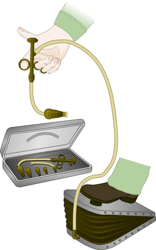
FIGURE 6-1 Fell-O’Dwyer apparatus. (From Mushin WW, Rendell-Baker L, Thompson PW, et al: Automatic ventilation of the lungs, ed 3, Oxford, UK, 1980, Blackwell Scientific.)
Attempting to circumvent the difficulties of tracheal intubation, in 1904, Sauerbruch developed a negative-pressure operating chamber that required the patient’s head to be sealed outside the chamber. Further development resulted in the electrically powered “iron lung” by Drinker and Shaw in 1928,10 which was widely used to treat patients with respiratory failure during the polio epidemics. In an alternative approach, in 1905, Brauer provided positive-pressure ventilation via the head, sealed within a chamber and thus eliminating the need for intubation or operating within a chamber (Fig. 6-2).11
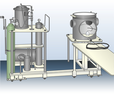
FIGURE 6-2 Brauer’s positive-pressure apparatus. (From Mushin WW, Rendell-Baker L, Thompson PW, et al: Automatic ventilation of the lungs, ed 3, Oxford, UK, 1980, Blackwell Scientific.)
Modern techniques of endotracheal ventilation during general anesthesia were initiated by Magill in 1928 for head and neck surgery.12 The beginnings of modern mechanical ventilation are attributed to Engström and his ventilator during the polio epidemics in Denmark circa 1952.13 This ventilator was later modified for use during general anesthesia,14 which stimulated the development of a huge number of anesthesia ventilators with a wide diversity of characteristic behaviors, mechanisms, and power sources. Gradually, designs were modified and eventually replaced by pneumatically controlled and fluidically time-cycled systems that were optional accessories for the anesthesia machine. These stand-alone ventilators substituted for the reservoir bag at the connection to the breathing circuit and took on the appearance of modern “bag in a bottle” double-circuit systems.
Contemporary anesthesia machines have replaced these freestanding ventilators by integrating the fresh gas delivery system, scavenging system, and ventilator into one unit. Modern ventilators have electronically controlled circuits and, in some cases, closed feedback loops with microprocessor-regulated flow control valves. Modern ventilators allow digital and graphic displays to aid in ventilator management.
Physiology and Mechanical Concepts
The two major functions of the lung are taken into consideration during mechanical ventilation: ventilation, the elimination of carbon dioxide (CO2), and oxygenation, the intake of oxygen (O2). A clear distinction should be made between the elimination of carbon dioxide and the intake of oxygen, even though these two processes are mechanically coupled during natural, spontaneous breathing and are interrelated at the metabolic level. Each is capable of stimulating ventilation.
Carbon dioxide elimination depends on ventilation, which means the lungs are inflated with non–CO2-containing gases. The carbon dioxide gas of metabolism enters the alveoli of the lungs, and the CO2-containing gas is expelled from the lungs on exhalation. As such, the achieved ventilation determines the partial pressure of CO2 in the arterialized blood (PaCO2).
Oxygenation is best represented by the partial pressure of oxygen in the arterialized blood (PAO2). Predictable improvements in oxygenation can be facilitated by enriching the inspired gas as dictated by the alveolar gas equation:
where PAO2 is the partial pressure of alveolar oxygen, FiO2 is the fraction of inspired oxygen, PB is barometric pressure, PH2O is partial pressure of water vapor at 37° C, PaCO2 is partial pressure of alveolar carbon dioxide, and R is the respiratory quotient. Increased oxygenation also can be accomplished by increases in airway pressure, which can recruit collapsed alveoli and redistribute alveolar fluid. These changes may be largely independent of ventilation.
Carbon Dioxide Equilibrium
The quantity of carbon dioxide produced normally dictates the minute ventilation. With the exception of using cardiopulmonary bypass or an extracorporeal membrane oxygenator (ECMO), no alternative method has proved satisfactory for eliminating carbon dioxide. Breathing is essential. Normally, in the absence of disease, high altitude, and pharmacologic intervention, spontaneous ventilation results in a PaCO2 of approximately 40 mm Hg. However, the quantitative relationship between CO2 production and minute ventilation often is poorly understood.
Carbon Dioxide Production
A resting adult weighing 70 kg produces approximately 0.008 gram molecules (moles) of carbon dioxide per minute. At standard temperature (0° C) and pressure (760 mm Hg), one mole of any gas occupies 22.4 L. Therefore, 0.008 moles of carbon dioxide occupy approximately 180 mL. At body temperature (37° C), this is approximately 200 mL.
Carbon Dioxide Elimination
Expressing carbon dioxide production either in moles or in milliliters at atmospheric pressure provides no insight into the volume of ventilation required to maintain homeostasis. More helpful information is provided when the same quantity of carbon dioxide is expressed at different partial pressures, using Boyle’s law (Table 6-1).
TABLE 6-1
Metabolic Production of CO2 Expressed at Different Partial Pressures
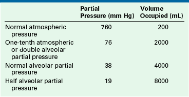
Each volume represents the minimum alveolar ventilation capable of achieving that partial pressure of carbon dioxide.
The volume of carbon dioxide shown at each partial pressure in Table 6-1 is the volume occupied by the metabolic production for 1 minute (0.008 moles). At each pressure, the volume shown is the volume of carbon dioxide produced and therefore is the least alveolar ventilation per minute that is capable of eliminating the carbon dioxide produced. Any lesser alveolar ventilation is insufficient to allow the carbon dioxide to escape at that partial pressure.
The patient’s minute volume is made up of both the alveolar and the total dead space ventilation. Normally, the dead space ventilation is one third of the minute volume. For an alveolar minute ventilation of 4000 mL, the required total minute ventilation therefore is approximately 6000 mL. The mixed expired carbon dioxide has a partial pressure of approximately 27 mm Hg.
During IPPV under anesthesia, the total dead space typically increases to approximately 45% of the tidal volume. The same alveolar ventilation of 4000 mL/min thus requires a total minute ventilation of approximately 7275 mL, which will eliminate a mixed expired partial pressure for carbon dioxide of approximately 22 mm Hg.
Oxygen Uptake
At rest, the 70-kg adult human has an oxygen consumption of approximately 250 mL/min. Strictly speaking, ventilation is not essential for oxygenation. When the patient is breathing oxygen, the pulmonary reservoir represents approximately 12 minutes worth of metabolic consumption. Furthermore, if a denitrogenated apneic patient is connected to an oxygen supply (apneic oxygenation), oxygenation theoretically is unlimited.15 In that case, survival is limited by carbon dioxide accumulation, not by hypoxia.
Net Effect of Respiratory Quotient
Respiratory quotient (RQ) is the ratio between carbon dioxide production and oxygen consumption. The production of carbon dioxide, such as 200 mL/min, normally is slightly less than the oxygen consumption, at 250 mL/min (RQ: 200/250 = 0.8). This discrepancy has interesting implications. With an RQ of 0.8, the sum of the arterial partial pressures for carbon dioxide and oxygen (PaO2 [100] + PaCO2 [40] = 140 mm Hg) will always be slightly less than the humidified inspired oxygen tension (PiO2 = 0.21 × [760 − 47] = 149 mm Hg) instead of being exactly equal to it. Because the minute volume inspired is slightly greater than that exhaled, a continuing, small, net inward movement of gas into the lungs is observed. At equilibrium, the partial pressure of nitrogen, or nitrous oxide (N2O), is slightly greater in the lung than in the inspired gas and, of necessity, this causes an equal reduction in the space that would have been available for the respiratory gases, carbon dioxide, and oxygen.
Physics of Gas Flow
Each ventilator discussed in this chapter has a selection of primary variables that the user may set. These may include any of the following:
| Inspired pressure: | PI |
| Peak inspiratory pressure: | PImax |
| Tidal volume: | VT |
| Minute volume: | VM |
| Inspiratory flow: | QI |
| Frequency: | f |
| Respiratory cycle time: | Tc |
| Inspiratory pause time: | Tplat |
| Inspiratory time: | TI |
| Expiratory time: | TE |
| Inspiratory/expiratory ratio: | I:E |
As spontaneous breathing occurs, work is done to move gas into and out of the lung. This work has been designated the work of breathing (WOB). Another way to view this is the energy expended to move the gas into and out of the lungs. It is well known that the total work of breathing (WOBT) is the sum of the work related to overcoming the elastic properties of the lung and chest wall (WOBE) and the work related to overcoming the resistance aspects of the circuit, endotracheal tube, and large and small airways (WOBR). Thus,
Under normal circumstances, the work related to overcome the elastance of the lung and chest wall is nearly 70% of the total WOB; the work related to overcome the resistance of the airways is nearly 25%, and approximately 5% is related to inertial properties of the tissues and gases. Elastance (E) of the chest wall is defined as the change of airway pressure (ΔP) divided by the change in volume (ΔV):
Elastance, however, is more commonly described by the inverse, compliance (C):
Experimentally derived, formulated, and published in the 1840s by Jean Louis Marie Poiseuille (1797–1869), Poiseuille’s law identifies the relationship of gas flow (Q) directly to the pressure gradient (ΔP) and identifies an inverse relationship to the resistance (R) of the system:
This equation can be manipulated to show that:
Because the purpose of the ventilator is to perform the work of breathing, it becomes advantageous to examine these physical relationships. In so doing, a method for classifying and understanding ventilator function using the “equation of motion” has emerged.16
The force exerted by a ventilator is measured as pressure. This pressure must overcome two distinct impedances to motion during inspiration: compliance and resistance. Exhalation is passive when mechanical ventilation is used and usually remains unaccounted. The pressure required to overcome the compliance properties of the lung and chest wall can be expressed as:
where Pc is pressure compliance. A second element of pressure required to overcome the resistance is found within the breathing circuit, the endotracheal tube, and the conducting airways. The pressure required to overcome this resistance may be expressed mathematically:
where PR is pressure resistance and QI is inspiratory flow. Because the ventilator exerts pressure to overcome both the compliance and resistance, these two equations may be combined during inspiration:
where PT is total pressure and PI is inspiratory pressure, or:
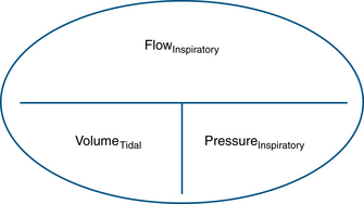
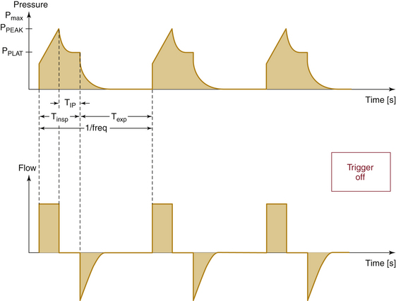
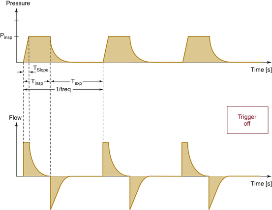
Compliance and resistance may be regarded as the “load” facing the inspiratory pressure that results in the two fundamental variables: tidal volume and inspiratory flow. Changes in inspiratory pressure result in changes in both tidal volume and inspiratory flow. Changes in a desired tidal volume can be achieved by changes in inspiratory pressure and/or flow. Changes in a desired inspiratory flow can be achieved as the result of changes in inspiratory pressure, tidal volume, or both. While using specific ventilator modes, a ventilator attempts to control the inspiratory flow rate to provide a “set” tidal volume or inspiratory pressure (Fig. 6-3). When the inspiratory flow is matched to a desired tidal volume, the inspiratory pressure varies to the given load (Fig. 6-4). When the inspiratory flow is matched to a desired inspiratory pressure, the tidal volume varies to the given load (Fig. 6-5).
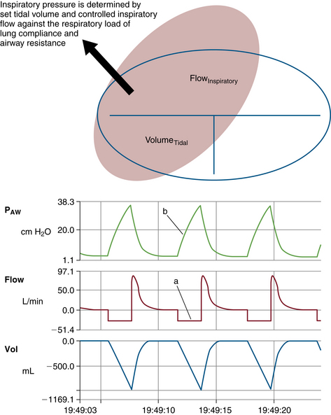
FIGURE 6-4 Relationship of controlled inspiratory flow and “fixed” or “set” tidal volume. An example of fixed flow on a 3-L anesthesia circuit reservoir bag with volume control ventilation settings. Notice inspiratory flow is constant (a) and inspiratory pressure rises linearly (b). PAW, airway pressure. (From Datex-Ohmeda S/5 Collect, v4.0. 2003. Courtesy GE Healthcare, Waukesha, WI.)
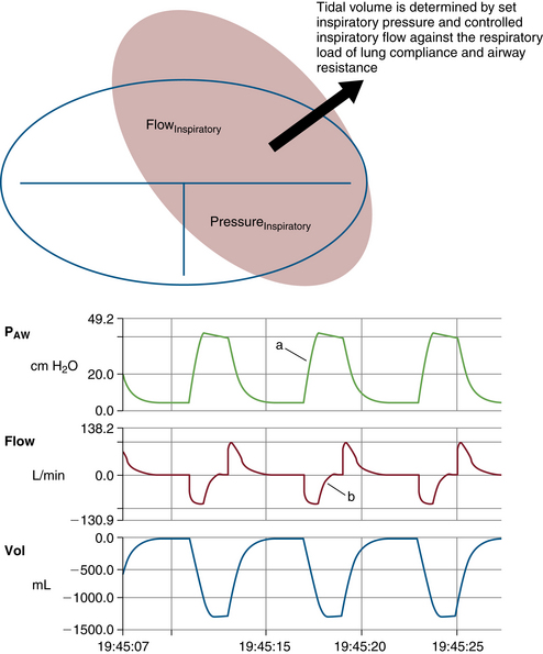
FIGURE 6-5 Relationship of controlled inspiratory flow and “fixed” or “set” inspiratory pressure. An example of a set pressure limit on a 3-L anesthesia circuit reservoir bag with pressure control ventilation settings. Notice inspiratory pressure rises sharply to the set pressure limit (a) and inspiratory flow rises sharply, then decays before exhalation (b). PAW, airway pressure. (From Datex-Ohmeda S/5 Collect, v4.0. 2003. Courtesy GE Healthcare, Waukesha, WI.)
Interdependence of Ventilator Settings
Many of these respiratory variables are interdependent, such as minute volume, tidal volume, and respiratory rate (VM = VT × f). In some ventilators, the tidal volume is determined by dividing the minute volume by the rate:
Tidal volume is also related to the inspiratory flow rate and the inspiratory time:
An inspiratory pause (plateau time [Tplat]) is a part of the inspiratory time. Because the inspiratory pause makes no contribution to the tidal volume, the equation for tidal volume may be modified:
Clinicians are also concerned about the relationship between inspiratory and expiratory time because the I:E ratio and the absolute times TI and TE affect ventilation and oxygenation. This ratio and the absolute time of inspiration are related to frequency and may be expressed mathematically.
Frequency determines time of the respiratory cycle (Tc), usually expressed in seconds, by the following relationship:
It follows that 60/f is equal to the inspiratory and expiratory times combined:
The relationship between TI and TE is conventionally expressed as the I:E ratio with 1 as the numerator. This ratio may be derived mathematically as follows, where RI:E equals I:E ratio:
(1) Seconds per minute devoted to inspiration:
(2) Seconds per minute devoted to exhalation:
(3) Dividing (1) by (2), the I:E ratio:
(4) The frequency and the inspiratory time can be derived by rearranging (3):
Depending on the manufacturer and the particular model of ventilator, the clinician must choose the RI:E (I:E ratio), mean QI (average inspiratory flow rate), or both. The reader is encouraged to study the manufacturer variations shown in Figures 6-6 to 6-13.
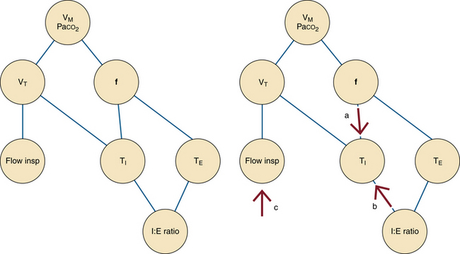
FIGURE 6-6 Interdependence of ventilator settings. VM, minute ventilation; VT, tidal volume; f, frequency or respiratory rate; Flow insp, inspiratory flow; Paco2, partial pressure of arterial carbon dioxide; TI, inspiratory time; TE, exhalation time; I:E ratio, inspiratory time to exhalation time ratio. Notice that the frequency and the I:E ratio are independent of one another. If tidal volume is fixed, changes in the respiratory rate (a) or I:E ratio (b) alter the inspiratory time. The inspiratory flow must then be adjusted (c) to maintain the fixed tidal volume at the new inspiratory time.
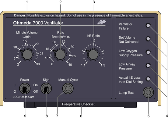
FIGURE 6-7 The Datex-Ohmeda 7000 ventilator (GE Healthcare, Waukesha, WI) requires the user to set minute volume and rate. Tidal volume must be calculated. Numbered components indicate the following: set minute volume (1), set frequency (2), set I:E ratio (3), warning lamps (4), switch to test the warning lamps (5), ventilator preoperative checklist (6), switch to activate one manual cycle (7), sigh function on/off (8), and power on/off switch (9).
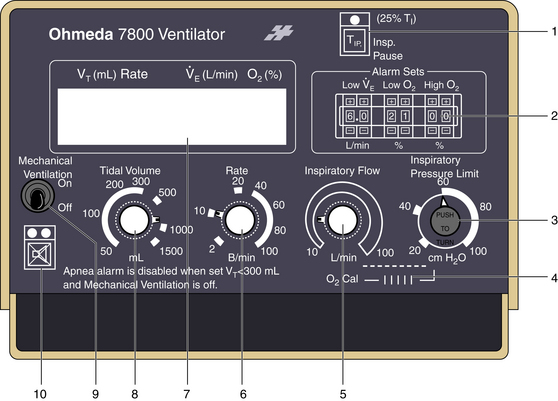
FIGURE 6-8 The Ohmeda 7800 ventilator (GE Healthcare, Waukesha, WI) allows the user to select inspiratory flow (5) to determine the rate at which the selected tidal volume is delivered. This selection alters the I:E ratio, which is announced in the liquid crystal display (7), which also displays ventilatory parameters and alarms. Compared with the Ohmeda 7000, the Ohmeda 7800 adds a pressure limiter (3) and a fixed inspiratory pause option (1). Additional numbered components include alarm limit sets (2), oxygen calibration dial (4), set frequency (6), set tidal volume and apnea alarm disable (8), power on/off switch (9), and alarm silence button (10).
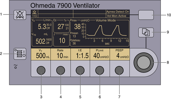
FIGURE 6-9 The Ohmeda 7900 ventilator (GE Healthcare, Waukesha, WI) allows the user to set desired tidal volume (as shown) or inspired pressure (3) in the volume-controlled or pressure generator modes, respectively. Compared with the Ohmeda 7800 ventilator, the user selects the I:E ratio (5) instead of the flow. Positive end-expiratory pressure (PEEP; 7) is an integral feature on the control panel. Dedicated displays of measured parameters are demonstrated. Other numbered components include the audible alarm silence button (1), mechanical ventilation on/off switch (2), select frequency (4), select inspiratory pressure limit (6), adjustment knob for the corresponding selection (8), select menu (9), and select apnea–volume alarm combinations (10).
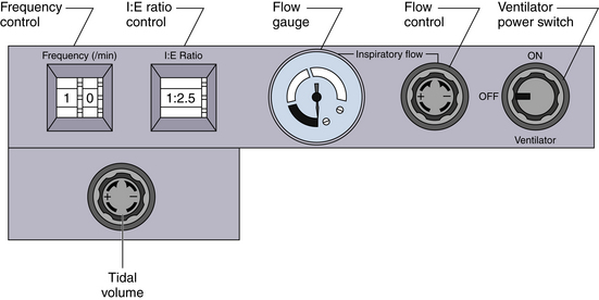
FIGURE 6-10 A unique feature of the Dräger AV ventilators (Dräger Medical, Telford, PA) is that both the inspiratory flow and the I:E ratio may be set by the user, creating a variable inspiratory pause within the preset inspiratory time.
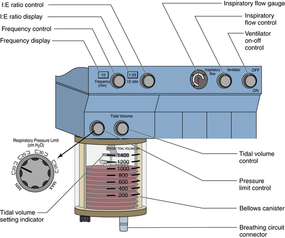
FIGURE 6-11 The Dräger AV-2 ventilator (Dräger Medical, Telford, PA) control panel adds a pressure limiter and digital displays of frequency and I:E ratio. The inspiratory flow and I:E ratio are set by the user, creating a variable inspiratory pause.
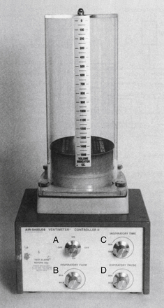
FIGURE 6-13 The Air-Shields Ventimeter Controller II. Shown are the on/off switch (A), the inspiratory flow control (B), the inspiratory time control (C), and expiratory pause control (D).
The following example demonstrates how frequency, tidal volume, flow, and I:E ratio are interdependent. Assume that in a 60-kg patient VT is 600 mL and f equals 10 breaths/min. As such, the cycle time is fixed at 6 seconds.
By choosing an I:E ratio of 1:2, the inspiratory time becomes fixed at 2 seconds, which mandates a mean inspiratory flow rate of 300 mL/sec or 18 L/min (300 mL/sec × 60 sec/min = 18 L/min). Choosing an I:E ratio of 1:1 increases the inspiratory time to 3 seconds, resulting in an inspiratory flow rate of 200 mL/sec or 12 L/min. An I:E ratio of 1:3 reduces the inspiratory time to 1.5 seconds, resulting in an inspiratory flow rate of 400 mL/sec or 24 L/min.
This situation is complicated somewhat by the selection of an inspiratory pause because the respiratory gases are not in transit into or out of the lungs. Exhalation begins when gases start leaving the lungs, so the inspiratory pause is considered part of the inspiratory phase of the respiratory cycle. When incorporated into the original example, with an I:E ratio of 1:2, the inspiratory time of 2 seconds would result in a mean inspiratory flow rate of 300 mL/sec or 18 L/min. In a situation in which Tplat equals 25%, TI is selected, and 25% of the original inspiratory time is added to the inspiratory time. This results in a changed I:E ratio. In this example, the inspiratory time is 2 seconds and 25% of the inspiratory time is 0.5 seconds, which results in a total inspiratory time of 2.5 seconds. Superficial calculations of inspiratory flow rate would suggest 240 mL/sec or 14.4 L/min flows. However, the ventilator would continue to deliver the inspiratory flow at 300 mL/sec or 18 L/min. Inspiratory flow is stopped at 2 seconds, achieving the 600 mL tidal volume, but exhalation occurs 0.5 seconds later. As such, the I:E ratio is changed without affecting the tidal volume, respiratory rate, or inspiratory flow rate. This pause at end inhalation allows for a mild increase in mean airway pressure, increased alveolar recruitment, and improved oxygenation (Fig. 6-14).
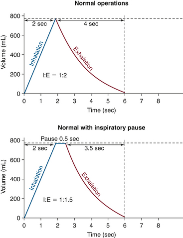
FIGURE 6-14 The effect of the inspiratory pause on the I:E ratio. (From Explore the anesthesia system. 1996, Ohmeda [now GE Healthcare, Waukesha, WI], pp 6-18.)
Primary selection of an inspiratory flow mandates the inspiratory time for the given 600 mL VT and thus determines the I:E ratio. For example, selecting a flow of 18 L/min (300 mL/sec) mandates an I:E ratio of 1:2 (VT /QI = TI):
At f = 10, each cycle is 6 seconds. Therefore expiratory time equals 4 seconds. The I:E ratio is 2 seconds relative to 4 seconds, or 1:2.
Some combinations of settings may exceed the capability of the ventilator. For example, a very low flow setting may not be able to deliver the 600 mL within the allotted 6-second cycle time. The alarm “VENT SET ERROR” will appear in the Datex-Ohmeda 7800 ventilator (GE Healthcare, Waukesha, WI) display (Fig. 6-15). In the Datex-Ohmeda 7800, with QI equal to 18 L/min, selection of the inspiratory pause of 25% will prolong the TI to 2.5 seconds, thus changing the I:E ratio to 1:1.4.
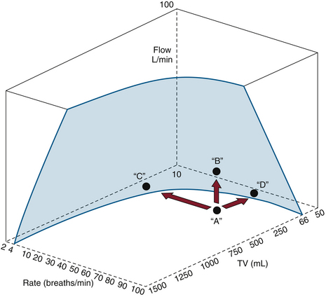
FIGURE 6-15 The limitations of the Datex-Ohmeda 7800 ventilator, illustrating the relationships among flow, frequency, and tidal volume. Only combinations of settings behind the shaded area are possible. In situation A, the message “VENT SET ERROR” appears and may be corrected by decreasing the rate C, increasing the flow B, or decreasing the tidal volume to D. (Courtesy GE Healthcare, Waukesha, WI.)
Other ventilators allow the selection of the I:E ratio and flow simultaneously. Three situations may result: 1) flow will be inadequate to deliver the selected tidal volume, 2) flow can be increased to create a variable end-inspiratory pause, and 3) flow can be just enough to depress the bellows to the bottom, thus delivering the desired tidal volume without a pause.
The final primary variable is the inspiratory pressure (PI). This variable can be set on some ventilators as a primary variable if the ventilator is in a pressure mode. In so doing, airway pressure increases very rapidly to the set level and is maintained at that level for the duration of the inspiratory period. This behavior must be distinguished from that of an airway pressure limiter, a passive device that does nothing more than prevent airway pressure (PAW) from exceeding a certain value. A Venturi ventilator can be set to function like a pressure generator if the flow is set to a high level and the pressure limiter is carefully adjusted to the desired peak airway pressure.
Lung Function During Anesthesia and Mechanical Ventilation
During anesthesia with a tracheal tube, lung function is adversely affected by many factors. Most of these factors are related to the physical aspect of a tracheal tube: retention of secretions as a result of cough suppression, interference and damage to the mucociliary elevator, increased insensible water loss by lack of humidification, inspissation of secretions by dry gases, and heat loss in exhaled gases. In addition, an increase in ventilation/perfusion (V/Q) mismatching occurs from changes in physiologic and mechanical dead space. The work of breathing may be increased from resistance changes to load related to the inner diameter and length of the tracheal tube.
Tracheal suctioning, the solution to the problem of airway secretions, has mixed risks and benefits. The removal of secretions from airways can improve oxygenation and ventilation, but the act of suctioning the secretions can cause negative airway pressure, resulting in atelectasis and entrainment of nitrogen that reduces the fraction of inspired oxygen. In addition, direct airway irritation by instrumentation can cause coughing and straining that can transiently affect the cardiac output and blood pressure.
IPPV causes an increase in intrathoracic pressure during inspiration. Elevated intrathoracic pressures can decrease the blood flow returning to the heart from extrathoracic blood vessels, which in turn decreases cardiac output. Venous return also can be decreased by positive end-expiratory pressure (PEEP), which increases intrathoracic pressure during exhalation.
Lung function can be improved by the use of a tracheal tube. Tracheal intubation can protect the airway from oral and gastric secretions, especially if a cuffed endotracheal tube is used, and it can establish a patent conduit for ventilation to occur. The latter occurs when upper airway obstruction is present. Mechanical ventilation can reduce the work of breathing and allow fatigued respiratory muscles a chance to recover. Mechanical ventilation allows consistent and predictable ventilation patterns, which removes the need for an anesthesiologist to ventilate manually for long periods. This also makes it possible to change ventilation strategies in response to changes in the surgical process, patient condition, and indicators of oxygenation and ventilation, such as capnography, oximetry, blood gases, and mechanical parameters that include airway pressure and resistance and lung compliance. In specific circumstances, appropriate modes of ventilation can improve the function of an abnormal lung during anesthesia. Finally, the delivery of medicines such as potent inhalational agents, helium, and other aerosolized substances through the tracheal tube with the aid of mechanical ventilation can relieve bronchospasm.
Lung Protection Strategies
Institution of IPPV is associated with the ever-present risk of traumatic lung injury. Barotrauma, or injury related to pressure, can be grossly manifested as a pneumothorax or more subtly as physiologic and pathologic changes related to alveolar overstretching. Volutrauma, injury related to volume, also can cause alveolar overstretching. Damage related to shear stress from the opening and closing of the alveoli, called atelectrauma or shear trauma, can be caused by both pressure- and volume-related changes. Airway irritation that causes patient/ventilator dissynchrony—coughing, bucking, and straining—can result in sharp changes in airway pressure, which can cause lung injury. Usage of PEEP can lessen the injury from shear trauma but also can result in increases in physiologic dead space and reduced cardiac output.
Disease states that affect the uniformity of the lung can increase the risk of lung injury. This happens when small segments of the lung have reductions in compliance compared with their normal counterparts. Previous assumptions about the relatively predictable distribution of the volume, pressure, and perfusion to the lung segments may no longer hold true; nondiseased segments receive a greater share of the tidal volume and effects of the inspiratory pressure and PEEP. As a result, these “good” lung segments can be injured, and physiologic changes related to V/Q mismatch maybe exaggerated. This can be seen in patients with congestive heart failure, pneumonia, and acute respiratory distress syndrome (ARDS).
Large tidal volumes (15 to 20 mL/kg) also have been used during anesthesia to maintain alveolar distension. Although this strategy effectively prevents atelectasis and reduces shunt fraction, it is now recognized as a potential cause of barotrauma. Overdistension of healthy alveoli can cause disruptions of the alveolar-capillary membrane and lead to pulmonary interstitial emphysema and pneumothorax. As already stated, the presence of diffuse lung disease may compound injury to remaining healthy alveoli. Tidal volumes of 6 to 8 mL/kg are now recommended, with the addition of PEEP.17,18
Complementing the recommendation of normal tidal volumes, safe peak inflation pressures now dominate ventilation strategies. Studies show that maximal alveolar pressures only slightly greater than 30 to 40 cm H2O may be associated with lung injury.17 Recent designs of anesthesia ventilators have all incorporated peak airway pressure limiters.
Optimal PEEP recruits collapsed alveoli and maximizes functional residual capacity (FRC). However, increases in PEEP beyond this point may overdistend patent alveoli without further recruitment of others. New strategies analyze static pressure–volume plots to determine optimal PEEP and safe peak inspiratory pressures. Optimal PEEP is usually 5 to 15 cm H2O.17
For the past 10 years, clinicians have been reducing tidal volumes even further for patients with acute lung injury (ALI) or ARDS. A landmark paper from the ARDS Network showed a reduction in mortality rate in a group with lower tidal volumes (6 mL/kg) compared with those in a control group (12 mL/kg).22 Ventilator settings that result in injury are attributed to diffuse alveolar damage that causes pulmonary edema, activation of inflammatory cells, local production of inflammatory mediators, and leaks of these mediators into the systemic circulation.23 Prospective studies are lacking to examine the use of lung protective strategies in the OR for non-ALI patients. The few randomized studies that have been done do not confidently demonstrate benefits in the OR, and some authors still recommend the avoidance of high plateau pressures (>20 cm H2O) and high tidal volumes (>10 mL/kg) in this patient population. The objective of this strategy is to minimize regional end-inspiratory stretch and thereby reduce alveolar injury and inflammation.23
Caution with tidal volumes and peak airway pressures is associated with an increased incidence of hypercapnia. Permissive hypercapnia promises to reduce ventilatory complications without adverse effects.19 Humans seem to tolerate respiratory acidosis well, with an arterial pH of 7.15 and a PaCO2 of 80 mm Hg. This strategy may be contraindicated in patients with increased intracranial pressure, recent myocardial infarction, pulmonary hypertension, or gastrointestinal bleeding.19 This is because acute increases in PaCO2 increase sympathetic activity, cardiac output, pulmonary vascular resistance, and cerebral blood flow and also may impair central nervous system (CNS) function.19
Inverse ratio ventilation (IRV) originated in the early 1970s as a method to improve oxygenation in neonates with hyaline membrane disease20 and was later extended to adults with ARDS. Although ratios were as high as 4:1, the benefits of this mode depend more on an absolute prolongation of inspiratory time in combination with a decreased peak inspiratory pressure. Typical I:E ratios of 1:2 to 1:4 have been lengthened to 1:1 or greater. The objective is to increase mean airway pressure and minimize peak pressure; the desired outcome is recruitment of collapsed alveoli without overdistension. Mean airway pressure directly corresponds with alveolar recruitment, reduction in shunt fraction, and oxygenation. Clinical evidence supports the contention that shunt fraction is reduced and oxygenation is improved, although modestly.17 Because pressure control is the desired outcome, this mode of ventilation is more commonly applied with pressure generators. Caution is advised when using IRV because this strategy may not allow adequate alveolar emptying, thus causing “breath stacking” and auto-PEEP. In addition, IRV is contraindicated in obstructive lung disease, such as asthma. It also may cause hypotension from a reduction in venous return since there is a higher inspiratory pressure for a longer portion of the respiratory cycle.
High-frequency ventilation (HFV), defined below, may be an applicable strategy during anesthesia, although some anesthesia ventilators are capable of rates only to 100 breaths/min. The conceptual advantage of HFV is a lower peak airway pressure combined with nonbulk flow of gas to provide a motionless surgical field. This technique has not proven clinically advantageous in patients with respiratory failure, but it is helpful in patients with large pulmonary air leaks. In addition, pulmonary complications in neonates may be reduced with this strategy.21
Classification, Special Features, and Modes of Ventilation
Historically, many different anesthesia ventilators have been produced over the years. Many of them incorporated features that are no longer considered valuable, but these serve in the general description and understanding of ventilator function. Commonly, such things as ventilator mechanisms, cycling parameters, and special clinical features were used to classify anesthesia ventilators.
Power Source
Most ventilators today function in an environment where electricity and compressed gases are readily available. In the past, however, some ventilators were designed to function solely on pneumatic gases. Currently, the only ventilators that function solely on pneumatic gases are not anesthesia delivery systems; these pneumatically powered ventilators are used in patient transport and in magnetic resonance imaging suites. Ventilators that use the bag-in-a-bottle design commonly have a double circuit in which a high-pressure driving gas, electrical circuits, and solenoids are used to achieve ventilator function. Some newer ventilators use electricity exclusively to drive the ventilator, which spares gas use for the patient.
Drive Mechanism
Classification of ventilators has been reduced to those that push or drive the patient gas to the patient, which is done by either a bellows or a piston.
Bellowed Ventilators
Bellowed ventilators have used two main varieties of bellows designs over the years: the ascending, or standing, bellows and the descending, or hanging, bellows. The designation of ascending or descending was based on bellows movement on exhalation; an ascending bellows moves up during exhalation (Fig. 6-16), and a descending bellows moves down (Fig. 6-17).
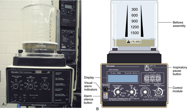
FIGURE 6-16 Bag-in-a-bottle bellows design, ascending bellows variety.
Ohmeda 7000 ventilator (left); illustration of Ohmeda 7800 ventilator (right) (GE Healthcare, Waukesha, WI). The bellows is contained within a clear housing, and a drive gas pushes the gas inside the bellows through the circuit. The bellows displayed in the images are deflated.
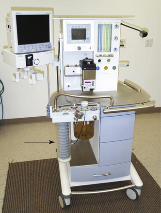
FIGURE 6-17 Bag-in-a-bottle bellows design, descending bellows variety. Shown is the Datascope Patient Monitoring Anestar anesthesia machine (Mindray North America, Mahwah, NJ) with descending bellows. The bellows (arrow) are in the inflated position.
In the event of a circuit disconnect or significant leak, an ascending bellows would not fill or would improperly fill during exhalation. This provides clinicians a visible monitor of ventilator function. Because of the improved patient safety, this type of bellows generally is preferred, but does not represent a standard according to the latest document by the American Society for Testing and Materials (ASTM F1109-90).24 The ECRI Institute has published a commentary and recommendations for hanging bellows in its Health Devices Alerts (1996-A40).
The hanging bellows, which typically is weighted, could fill whether a circuit disconnect, leak, or normal exhalation was present. Room air could enter the circuit and allow the bellows the ability to return to its filled position. In association with fresh gas decoupling, hanging bellows ventilators rely on a separate reservoir bag to detect leaks and inadequate fresh gas flow (FGF).
Bellows designs are not without inherent problems. Because a high-pressure gas typically is used to drive the bellows, a hole or perforation in the bellows can subject the patient to driving gas pressures and result in barotrauma. In addition, mixing of the patient circuit gas with the driving circuit gas may cause unpredictable concentrations in oxygen. Typically, 100% oxygen is used as the driving circuit gas. When high oxygen concentrations are undesirable or the potential for an airway fire exists, leaks into the patient circuit gas may cause disastrous consequences. When air is used as the driving circuit gas, unexpectedly low concentrations of oxygen may be observed. In both circumstances, patient awareness may occur because the driving gas may dilute the intended gas concentrations of inhaled anesthetics to be delivered to the patient. In addition, hypoventilation may occur if the bellows is not properly seated inside the bellows assembly.
Piston Ventilators
Piston ventilators rely on a piston-cylinder configuration, in which an electric motor is used to drive or displace the piston within the cylinder to cause gas flow. Tidal volume accuracy is believed to improve because the precise position of the piston during inspiration is monitored from start to finish; the motor returns the piston to the filled position prior to the next delivered breath. The drive motor requires maintenance and usage monitoring for good function because ventilator failure has been reported from worn motor parts. A leak occurring at the piston diaphragm could cause a loss of circuit gases to the room with hypoventilation during inspiration. Entrainment of room air into the patient circuit could occur as the piston returns to the filled position. Some recent designs have placed the piston ventilator within the workstation housing to make visible operation impossible. Piston-driven bellows currently manufactured by Dräger Medical (Telford, PA) have placed the piston in both vertical and horizontal positions in different models. Such systems use fresh gas decoupling with a separate reservoir bag, which is monitored for circuit leaks or inadequate FGF.
Cycling Behavior
Cycling behavior is believed to be one of the most complicated concepts in ventilator classification and description. In a normal ventilator breath, two significant events occur: inspiration and exhalation. However, cycling behavior describes the event that transitions the ventilator from exhalation to inspiration and from inspiration to exhalation. In sequence, the ventilator cycles from exhalation to inspiration, inspiration occurs, the ventilator cycles from inspiration to exhalation, and exhalation occurs. For most modern anesthesia ventilators, respiratory rate and I:E ratio are set in controlled modes, either by volume control ventilation (VCV) or pressure control ventilation (PCV); time cycles the breath from exhalation to inspiration and from inspiration to exhalation. A trigger can be used to initiate inspiration on spontaneous patient effort in pressure support ventilation (PSV). The trigger, an observed parameter to allow inspiration to occur, can use pressure, volume, or flow values. As will be seen, the method of delivering the inspired breath also can be manipulated. Cycling from inspiration to exhalation can occur as a result of achieving a set volume, pressure, flow, or time.
Exhalation typically is a passive event. Pressures in the airway can be manipulated during exhalation by the addition of PEEP. More recent developments in ventilator cycling allow the cycling from exhalation to inspiration to include uses of airway pressure, volume, and flows in the ICU. However, most anesthesia ventilators still use time as the determinant to cycle from exhalation to inspiration.
Many machines can function in at least two modes; the most common example is the ventilator that normally cycles when a given time or tidal volume is reached. In the Datex-Ohmeda 7800 series, reducing the pressure limit makes the ventilator cycle when a given pressure is reached. By contrast, in the Dräger AV-2+, the inspiratory phase is not ended; the bellows is held in its compressed state by the continuing flow of drive gas, which escapes to the atmosphere through the pressure-limiting valve. These mechanisms afford a poor basis for classification because, as demonstrated, they may not indicate functional behavior.
Inspiratory Flow
The inspiratory flow classification describes the method used to make a breath: either a flow generator or pressure generator. A flow generator is used in ventilation when the inspiratory waveform is controlled around the use of a high-pressure source; the source in this case is typically greater than five times the airway pressure. A pressure generator is used when the pressure waveform is controlled around the use of a low-pressure source, usually near or moderately higher than the airway pressure.
When a high-pressure source is used, changes in patient compliance and resistance have little effect on the inspiratory flow waveform. As such, a fixed or constant flow can be established to generate a reliable tidal volume breath for a given inspiratory time. This type of ventilator is called a constant flow generator.
With a low-pressure source, changes in patient compliance and resistance affect the inspiratory waveform. As a result, the pressure waveform is controlled because it is not affected by patient changes and the use of a low-pressure source. Mechanisms used to achieve this behavior of constant airway pressure during the inspiratory period include the use of a spring or weight on the bellows. This is what is known as a constant-pressure generator. On inspiration, a large pressure gradient exists from the ventilator to the alveoli that results in high initial gas flows. Rising gas volumes in the lung slowly equilibrate pressures between the ventilator and lung to cause a diminishing inspiratory flow; the delivered tidal volume is the result of the variable flow related to the equilibrating pressures between the ventilator and lung and the time allotted for inspiration to occur.
Some flow generators can vary the inspiratory flow to provide different flow waveforms; that is, increasing flow (ascending ramp), decreasing flow (descending ramp), or sinusoidal flow may be selected. This type of ventilator is called a variable-flow generator. Modern flow generators can provide pressure generator behavior by using negative feedback to vary the orifice of the inspiratory flow control valve during inspiration.
Classification by inspiratory flow should not be confused with the volume- or pressure-control modes of ventilation. Modern ventilators can now switch between flow and pressure generator methods. In addition, both flow and pressure generators can achieve the same modes of ventilation by advances in sensor application and electronic feedback control.
Control of the Pressure and Flow Waveform During Ventilation
The pattern of ventilation occasionally used has a critical influence on lung function. The most common example in the OR is the hypotension that accompanies hyperventilation. In critical care, greater attention is given to optimizing lung function by appropriate selection of the inspiratory waveform. For example, several advantages have been proposed for using a decelerating waveform: the maximum pressure is minimized, the risk of barotrauma is diminished, alveoli are kept expanded, V/Q ratios are more uniform, and distribution of gas within the lung is facilitated.
Controlled ventilation also tends to affect venous return and cardiac output. To a large extent, the best strategy to optimize cardiac output is the reverse of that which promotes improved lung function. A relatively short inspiratory period, with no time for distribution and no plateau, will have the least effect on the mean intrathoracic pressure and therefore on venous return.
Debate about the potential benefits of variation in the inspiratory waveform has persisted for at least 35 years. The expense and complexity required to achieve such waveforms have been critically discussed since the early 1960s. In the OR, fine control of the inspiratory waveform usually is not provided or needed. To this day, many anesthesia ventilators offer no control of the inspiratory waveform, and the anesthesiologist must occasionally approximate a desired pattern with the equipment available.
Constant Inspiratory Flow
Most anesthesia ventilators are powered by a high-pressure gas source. For practical purposes, flow is not affected by the patient, and it remains constant during the inspiratory period (see Fig. 6-4).
Declining Inspiratory Flow
Declining inspiratory flow allows time for gas redistribution at the end of inspiration. An anesthesia ventilator can be set to approximate this pattern by continuing the normal inspiratory flow rate until the lung is filled and then maintaining a plateau for distribution; this minimizes the time required to fill the lung and maximizes the time for redistribution. Many anesthesia ventilators have this option. It is very rare for a patient to be so dependent on a critical pattern of decelerating inspiratory flow that this approximation does not suffice (see Fig. 6-5).
Accelerating Inspiratory Flow
An accelerating inspiratory flow pattern is intended to achieve ventilation while minimizing the effect on intrathoracic pressure. In a patient in whom this is beneficial, the anesthesia ventilator can approximate this pattern by prolongation of the period for exhalation, followed by a rapid inspiration with no plateau. The prolongation of the expiratory period maximizes the time for venous return. The time devoted to filling the lungs, which adversely affects venous return, is reduced to the minimum. No data supporting the use of accelerating inspiratory flow are available.18
Sinusoidal Inspiratory Flow
Once promoted as mimicking normal ventilation, the sinusoidal inspiratory flow pattern was provided by the Engström and Emerson piston ventilators. Some thoracic surgeons preferred this pattern because it provided a smoother transition from inspiration to exhalation and vice versa. Ventilators that offer this pattern of inspiratory flow are no longer in general use.
Improvement in Control
Closed-loop negative feedback can be used to improve performance in a controlled category, such as flow or volume. Some newer machines measure either the machine’s delivered flow or the delivered tidal volume; these measures allow more accurate control of the ventilator to improve its performance. Unfortunately, better control of the volume or flow at the ventilator still tends to be offset by the compliance and resistance of the circuit itself because the measurements of flow and volume are not routinely made at the tracheal tube. The most modern technique to date uses automatic self-measurement of the ventilator and breathing circuit compliance; this enables accurate calculation and delivery of flow and tidal volume, as seen in newer GE Healthcare and Dräger workstations. Other preexisting technologies, such as spirometry, use sensors placed at the endotracheal tube that enable accurate measurement of delivered and exhaled volumes, pressure, compliance, and resistance. However, such technologies are not always set up to influence the ventilator automatically.
In units with closed feedback loops, microprocessors attempt to maintain the designated variable constant by processing data hundreds of times per second and by regulating the flow control valve with equal frequency. Feedback may be helpful in the midst of changing clinical conditions such as bronchospasm, secretions, or even a leak in the system. Open-loop systems cannot compensate for these external loads and eventually fail to deliver the prescribed parameter, which requires vigilance and adjustments by the anesthesiologist.
Special Ventilator Features
Many other valuable features may be available on a given ventilator. These features are less suitable as tools to classify ventilators, even though they may be critically important when managing a particular patient.
Inspiratory Manipulation
Inspiratory Plateau or Inspiratory Hold
A tidal volume maintained after the inspiratory flow ceases, a so-called plateau or inspiratory hold, provides an opportunity for gas to redistribute within the lung. This maintained pressure may also improve gas exchange by keeping alveoli expanded for a longer period, thus reducing shunt fraction. In addition, the pause facilitates the measurement of static lung compliance. The potential penalty of a plateau, particularly in a hypovolemic patient, is that the increased intrathoracic pressure may impede venous return and decrease cardiac output. Inspiratory hold also affects the I:E ratio (see Fig. 6-14).
Inverse Ratio Ventilation
Modern anesthesia ventilators have recently offered IRV as a means of increasing mean airway pressure without increasing peak airway pressure.25,26 Inverse ratio ventilation is defined as an I:E ratio greater than 1:1. It has physiologic effects similar to the inspiratory pause described above. The ratio may be inverted in ventilators that use both flow generator (FG) or pressure generator (PG) modes. When FG-IRV is used, the I:E ratio can be inverted only by decreasing the mean inspiratory flow or by adding an end-inspiratory pause. For the same minute ventilation and I:E ratio, the inspiratory pause provides a greater mean airway pressure than does the lower flow rate of the first option.25-27 When using IRV, caution is advised to prevent breath stacking and auto-PEEP. This can occur if there is inadequate time for exhalation; using IRV with a PG merely prolongs the inspiratory time.
Expiratory Manipulation
Positive End-Expiratory Pressure
Most anesthesia ventilators now routinely provide PEEP. At the end of each breath, the pressure is commonly maintained at an end-expiratory pressure of 2 to 4 cm H2O above zero because of the weight of valves and bellows, although some anesthesia ventilators provide a direct control to set additional PEEP. When lung function is less than optimal, PEEP may be added to improve oxygenation by alveolar recruitment. This is a more logical response to desaturation than merely increasing the inspired oxygen concentration because it is better to improve the function of the lung than to conceal the evidence of dysfunction. Because PEEP can affect the venous return to the heart, careful monitoring of the hemodynamics is advised.
Expiratory Retard
The introduction of a constrictive orifice during exhalation can benefit some patients with advanced lung disease. This is due to the fact that expiratory retard will decrease the expiratory flow rate and allow more laminar flow and better emptying of the lung. This modality can be useful in patients with severe bronchoconstriction, such as those with status asthmaticus. It is similar to the pursed-lipped breathing seen in asthmatics; air trapping is minimized, and exhalation may, paradoxically, be improved. This modality is rarely incorporated in anesthesia ventilators today because it carries the risk of incomplete exhalation (breath stacking) if the frequency is suddenly increased, which would cause a potentially dangerous high pressure. The clinician must always be sure that the end-expiratory pressure is zero.
Interactions with the Breathing System
Fresh Gas Flow
In combination with oxygen, anesthetic gas typically flows continuously from the common gas outlet of the anesthesia machine into the breathing circuit. In some ventilators, FGF is directly delivered into the ventilator bellows, which is preloaded under a certain degree of spring tension, called the working pressure. These ventilators (e.g., Servo Ventilator 900C [Siemens-Elema AB, Solna, Sweden]) store fresh gas for every cycle, mandating an FGF at least equal to the minute volume. FGF commonly contributes to actual delivered tidal volume if it continues to flow into the breathing circuit during the inspiratory phase. This contribution is measured by:
where VFGF is the volume of FGF. For example, at an FGF of 3 L/min and a TI of 2 seconds, the FGF contribution to tidal volume is calculated as follows:
New designs of ventilators offer fresh gas uncoupling by electronically interrupting or diverting the FGF during the inspiratory phase. Others compensate for the FGF by first measuring total delivered flow and then adjusting the next breath through servo mechanisms.
Scavenging Systems
Modern dual-circuit ventilators have an integral ventilator pressure relief valve at or inside the bellows that is sealed during inspiration and at the beginning of exhalation, until the ascending bellows has been refilled. This ventilator pressure relief valve provides a minimum mandatory level of PEEP, usually 2 to 3 cm H2O, and then releases anesthetic gas into the scavenging system once the bellows is full. Typically, this waste gas travels directly to the scavenging system, although newer technologies, such as those designed into the Datex-Ohmeda 7900, incorporate this gas flow into a PEEP-generating mechanism, discussed below. Similarly, ventilator drive gas is commonly vented to the atmosphere, although it may be routed to the scavenger. The Datex-Ohmeda workstations (Avance, Aespire, and Aisys) have an adjustable needle valve in the scavenging system. Improper adjustment of this valve can result in 10 cm H2O of PEEP being applied to the patient circuit. Unintentional PEEP could result in improved lung function, but also cause hypotension or barotrauma.
Capabilities and Limitations of Anesthesia Ventilators
Anesthesia Versus Critical Care Ventilators
Historically, the anesthesiologist was limited in the type of ventilation that could be delivered to a patient. A number of reasons allowed for this limitation: 1) most surgical patients did not have pulmonary disease, 2) widespread use of muscle relaxants enabled complete control of ventilation without patient interaction, 3) the anesthesiologist was immediately available to makes changes in the ventilator settings and/or provide manually assisted ventilation, 4) use was intended for short duration, and 5) recirculation of patient gas was desirable. All these factors focused ventilator design to function only in the control mode.
In contrast, critical care ventilators became far more complex because they were used in different conditions. A trend is now apparent: anesthesia ventilators are are being manufactured to mimic the performance of their critical care counterparts while maintaining the simplicity of complete control. However, critical care ventilators offer ever-increasing complexities of flow and pressure waveforms that may not be needed, desirable, or available in anesthesia ventilators.
Ventilator Performance
Perhaps the most distinguishing characteristic of any ventilator is its performance under extremes of load—in effect, under conditions of very poor compliance. Information regarding performance of individual ventilators may not be readily available in the manufacturer’s literature and is scarcely available in the scientific literature.28,29 The American National Standards Institute (ANSI) specifies set values for compliance, resistance, and flow within a test lung as the conditions under which breathing machines for patient use should be tested to determine their performance capabilities.30 Although the operator’s manual may specify certain maximum capabilities, these numbers should be regarded as ideal figures under conditions without load. Some manufacturers specify the conditions under which their ventilator is tested, thus giving a basis for reported accuracy data.31 One study clearly demonstrates the limitations of anesthesia ventilators when subjected to increasing airway pressures.28 Minute ventilation decreased linearly for some ventilators as airway pressure increased; however, the Siemens 900D maintained its minute volume when the airway pressure was below 60 cm H2O. This might be attributed to the design of a nonrebreathing system without compression loss in the absorber.
System Compliance and Compression of Gas
As previously stated, gas compression and compliance volume losses caused by expanding hoses explain why delivered tidal volumes are frequently less than desired. Loss of tidal volume is greatest and most variable in machines that have an external ventilator connected to a circuit that includes a soda lime absorber and a humidifier. This is because the compressible volume is large, there is a greater total length of compliant breathing hose, and the change in pressure during each breath affects the gas in the entire circuit, including the bellows. The total volume of the gas that may be compressed in the circuit often exceeds 6 L. The amount lost due solely to gas compression may then be calculated; for every 10 cm H2O pressure, approximately 1% of the compressible volume is lost from the circuit. Boyle’s law (P1V1 = P2V2) explains this phenomenon. Boyle’s law can be applied such that the resultant volume (V2) is calculated by knowing the original volume (V1) and pressure (P1) and the secondary pressure (P2). For example, if compression of V1 (6000 mL) increases the pressure 10 cm H2O (1%) above atmospheric pressure (P1 = 1000 cm H2O and P2 = 1010 cm H2O), the resultant volume (V2) will be 5941 mL, or approximately 1% less. This would equal a loss of 120 mL at 20 cm H2O for a 6 L system. Next, the amount lost due to expansion of the system must be calculated by using compliance specifications from the manufacturers of the ventilator and the breathing hose. These losses typically are overcome by default of FGF, which at 3 L/min would add 100 mL to the circuit during a 2-second period of inspiration.
As the complexity of ventilators has increased, their ability to deliver the intended volume has improved. New designs with fresh gas decoupling do not contribute any fresh gas to the delivered inspiratory volume; they have low-volume, noncompliant metallic manifolds, they calculate and sequentially compensate for circuit and patient compliance and gas compression losses, and they may subtract the breathing hose volume compensation from the measured exhaled volume to report an actual exhaled volume.
Atmospheric Pressure Variations
At least one anesthesia ventilator (Siemens Servo 900B) has been tested under hyperbaric conditions (1 to 3 atm), which cause increases in gas density, resistance to flow, and dead space ventilation.32,33 Minute ventilation was found to decrease linearly as atmospheric pressure increased, but the ventilator functioned well as long as compensation was made to restore the minute ventilation.34 Different ventilators have variable outputs in flight because of lower barometric pressures, but they may be used under these conditions during military emergencies. Their performance is determined by the type of control circuit, fluidic or electronic, and the method of powering the ventilator because gas density decreases at increased altitude. Differences in the mass versus volume of gas used to control these units are responsible for the alterations in function.35 In general, effective ventilation at abnormal ambient pressure depends on providing the patient’s usual minute volume. Carbon dioxide continues to be eliminated at the usual partial pressure but is accompanied by either a smaller or greater mass of other gases.
Mode Conversion
With the appearance of pressure generator capabilities within the OR, the opportunities for conversion from flow to pressure generator systems will increase. The clinician should first record the tidal volume and frequency; peak, mean and plateau airway pressures; PEEP; and I:E ratios while in flow mode. The emphasis of the conversion is on the maintenance of plateau pressure because inspiratory, peak, and plateau pressures are merged into the square-wave airway pressure profile. Whether desired and set inspiratory pressure is absolute or whether it is a set pressure above PEEP should be noted. Leaving PEEP and frequency the same, the inspiratory time—and therefore the I:E ratio—should now be set to equal the total inspiratory time from the flow generator mode, accounting for inspiratory pause. Next, a change in modes must be initiated and the new parameters are measured; mean airway pressure should be slightly higher, considering the new airway pressure profile. Minor increases in set inspiratory pressure usually are necessary to match tidal volume.27 For convenience, some modern ventilator designs are able to apply an algorithm automatically on conversion from a volume to pressure mode, or vice versa.
Modes of Ventilation
Recently, advances in ventilator technologies have included improved microcircuit designs and applications, pressure and flow sensor enhancements, and better material design and use features that have improved the performance regardless of classification. Precision, accuracy, and reliability lie in the delivery of volume and pressure over great lengths of time and under a variety of clinical conditions. Adjunct technologies in waveform display and monitoring allow the rapid adjustment of ventilator parameters to meet dynamic intraoperative objectives.
In addition, alarms have been designed around these improved sensors and monitors, which in turn allow the delivery of safer mechanical ventilation regardless of the mode of ventilation. As such, the actual mode (method) of ventilation may be less important when endpoints of oxygenation (saturation of arterial oxygen [SaO2], pressure of arterial oxygen [PaO2]), ventilation (end-tidal carbon dioxide [ETCO2], pressure of arterial carbon dioxide [PaCO2]), tidal/minute volume, or airway pressure are managed. This may be supported by the lack of scientific literature regarding the benefits of specific modes of ventilation in the OR, except in pathophysiologic outliers.
Ventilator modes can be divided into three basic categories: 1) controlled breathing modes, 2) assisted or supported modes, and 3) spontaneous breathing without assistance or support. Division into these categories allows the user to define whether the ventilator is doing all of the work of breathing, some of the work of breathing, or none of the work of breathing, respectively. The vocabulary, however, is difficult and less than perfect—the result of historic developments, imprecise usage, and technologic advances. The use of dual modes of ventilation, especially in ventilator weaning, has added to conceptual difficulties.
Controlled Breathing Modes
In controlled breathing modes of ventilation, the patient cannot contribute any effort toward the work of breathing. Such situations commonly occur with nondepolarizing neuromuscular blocking agents, such as pancuronium. The variable to be controlled—fixed, targeted, or limited—defines the mode.
Volume-Control Ventilation
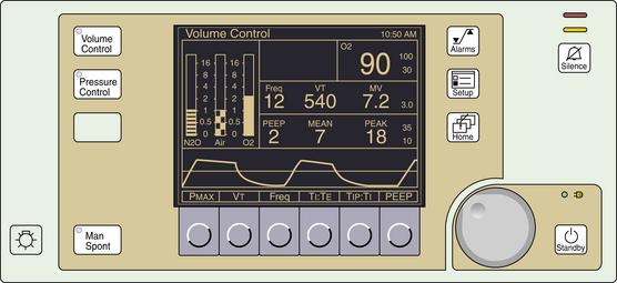
If volume is the fixed parameter, then the ventilation mode is volume-control ventilation (VCV). Modern ventilators in VCV mode require the parameters of tidal volume, respiratory rate, and I:E ratio to be set. The ventilator calculates the inspiratory time from the respiratory rate and I:E ratio, and a fixed flow for gas delivery is determined using the set tidal volume and calculated inspiratory time. Airway pressure rises linearly with time as the gas volume is pushed into the lung. The peak airway pressure is directly related to airway resistance and inversely related to lung compliance (Fig. 6-18). As such, worsening airway resistance (bronchospasm, secretions, mucus plugging) and lung compliance (fluid overload, abdominal distension) can place the patient at risk of barotrauma; therefore vigilance should be applied in the monitoring of peak airway pressure when using VCV.
Pressure-Control Ventilation
If pressure is the fixed parameter, the ventilation mode is pressure-control ventilation (PCV). In this mode, the peak airway pressure is controlled. The user must set the peak airway pressure, respiratory rate, and I:E ratio. As with VCV, the inspiratory time is calculated using the respiratory rate and I:E ratio; however, in this mode, the flow is varied to match the set peak airway pressure. This is accomplished by variable flow control. High flows are delivered at the start of inspiration, and the flow is rapidly diminished while maintaining the pressure constant. In addition, the flow tends to drop in an exponential decay over time. The tidal volume is directly proportional to lung compliance and inversely to airway resistance, so worsening airway resistance and lung compliance result in potentially inadequate oxygenation and ventilation (Fig. 6-19). An emphasis is placed on monitoring tidal volume and carbon dioxide when PCV is used because it is difficult to preset appropriate minimum and maximum volume alarms when initiating PCV.
Volume Guarantee Pressure-Control Ventilation
A recent advanced mode of PCV called volume guarantee PCV, or VG-PCV, seen in Datex-Ohmeda ventilators, allows the ventilator to change the inspiratory pressure dynamically based on the compliance of the respiratory system. In a steady-state system using PCV, a sudden improvement in pulmonary compliance would result in large tidal volumes and hyperventilation. An example of this can be seen during abdominal laparoscopic procedures, when the insufflation pressure is suddenly lost. Large tidal volumes and hyperventilation would occur until the insufflation pressure was reestablished or the anesthesiologist manually adjusted the ventilator. VG-PCV would allow the ventilator to adjust the inspiratory airway pressure dynamically over several breaths to maintain tidal volumes and ventilation parameters at a constant. Alterations in the pulmonary system that result in reduced compliance allow the ventilator to increase the set inspiratory pressure limit, which leads to an increase in the tidal volume and ventilation over several breaths; therefore the clinician must be vigilant in the adjustment of the peak pressure alarm.
Assisted and Supported Modes
In assisted and supported modes of ventilation, both the patient and the ventilator can contribute to the work of breathing. At times, the patient may be doing some or most of the work of breathing; at other times, the ventilator may contribute little to the work of breathing or the ventilator may be doing it all. These modes were developed as a solution for the pulmonary recovery of critically ill patients. As a group, these patients typically required long-standing intubation and mechanical ventilation. In the OR, these modes may allow augmentation of the patient’s breathing effort while anesthetized. When native breathing can occur, the patient’s effort is assisted, supported, or synchronized with mechanical breathing. Because the mechanical effort occurs while the patient is attempting to breathe, patient-ventilator dissynchrony is minimized, which in turn decreases coughing, bucking, and straining during surgery. The transition from effortless breathing to spontaneous breathing during an anesthetic emergency is commonly associated with risks of hypoxemia, hypercarbia, and dissynchrony. It is believed that these modes facilitate this transition by synchronizing with the patient’s effort while maintaining minimum set minute ventilation.
Assist-Control Ventilation
Assist-control ventilation (ACV) is the improvement to assisted ventilation (AV). In AV, the patient’s effort to breathe is manifested as a negative deflection in the airway pressure, and a predetermined negative pressure triggers the ventilator to deliver a set tidal volume. The user can set the trigger for small or large efforts based on the magnitude of the negative deflection. Historically, hyperventilation occurred from overtriggering that caused apnea and hypoxemia. The improvement is ACV, in which the technician sets up the ventilator the same as in VCV and the patient is able to trigger the ventilator by respiratory effort. As long as the patient triggers the ventilator more than the interval defined by the set control rate, a control breath will not be delivered. If the patient has a pause or does not breathe, controlled breaths will be delivered to the patient without being triggered, which will make this mode perform exactly like VCV. The minute ventilation is the sum of the delivered control breaths and the patient’s triggered breaths. The distinguishing feature between the two breaths (assisted vs. controlled) is the presence or lack of negative deflection in the airway pressure-time waveform, respectively.
Proportional Assisted Ventilation
Few OR ventilators use ACV, although it is not uncommon to place patients on this mode upon arrival to an ICU. For ICU patients going to the OR, VCV will substitute once the patient is anesthetized. Recently, ACV has further evolved into a new mode of ventilation called proportional assisted ventilation (PAV). The new feature, proportion, allows the tidal volume to correlate to respiratory effort, and more negative effort is rewarded with greater tidal volumes. In the past, pressure-triggering mechanisms were the only way to trigger the ventilator. Recently, these mechanisms have competed with flow-triggering mechanisms as the trigger of choice.
Pressure Support Ventilation
Pressure support ventilation (PSV) is the pressure equivalent of AV. In PSV mode, the clinician sets the inspiratory time, peak airway pressure to be delivered, and the trigger (Fig. 6-20). Some believe that this mode of ventilation addresses patient load issues related to compliance and resistance better than volume delivery techniques. As such, it could be considered more physiologic. Despite the lack of evidence for this claim, it has become a popular mode of ventilation in ventilator weaning in the ICU. Low-pressure PSV breaths are believed to match the resistance effects of the endotracheal tube. Use in this manner allows clinicians to equate resulting tidal volumes as the patient’s own effort and ability to overcome respiratory load. In the OR, this mode has been successfully used in adults and children to support patient breathing efforts during general anesthesia with an endotracheal tube and laryngeal mask airway. An apnea alarm and backup mode are provided for PSV mode in the OR because dynamics of the surgery and anesthetic could unexpectedly alter respiratory effort.
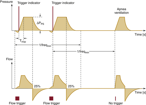
FIGURE 6-20 Graph of pressure and flow traces for pressure support ventilation. Shown are time-pressure (upper) and time-flow (lower) representations. Pressure or flow can be used to trigger the ventilator to cycle. The pressure trigger is indicated as a negative deflection in the pressure trace prior to inspiration; the flow trigger is indicated as inspiratory flow prior to main inspiratory pressure and flow changes. When no triggering has occurred, the ventilator will cycle without the triggering indices. (Courtesy Dräger Medical, Telford, PA.)
Intermittent Mandatory Ventilation
In intermittent mandatory ventilation (IMV), the clinican sets mandatory ventilator breaths by either volume or pressure at a defined rate and inspiratory time. Mandatory means that the patient is guaranteed the set mechanical breaths. Between breaths, however, the patient is afforded the luxury of displaying native effort. The effort can be as simple as spontaneous breathing with or without airway pressure. Also, assisted or supported breaths can be delivered between the mandatory breaths. This mode was developed for ventilator weaning and mandates a defined minute ventilation but also affords the patient the ability to exercise respiratory muscles between mandated breaths. The problem with this mode of ventilation is the risk of the patient getting a mandatory breath while not having completed a spontaneous or assisted breath. Resulting breath stacking puts the patient at risk for barotrauma.
Synchronized Intermittent Mandatory Ventilation
To avoid breath stacking, a refined mode of IMV was created called synchronized intermittent mandatory ventilation (SIMV). As with IMV, a mandatory volume or pressure, breath rate, and inspiratory time are set by the technician, and respiratory intervals are calculated for the breaths, the rate of which is known. What makes SIMV different than IMV is the ability to give a mandatory breath at the beginning or the end of the interval. This is accomplished by placing a time observation window at the beginning of each respiratory interval. This time window allows the ventilator to monitor the status of the airway for pressure or flow changes from baseline. If the pressure or flow does not exceed the set limit parameters, the mandatory breath is delivered at the beginning of the respiratory interval. If the pressure or flow exceeds the set parameters, the mandatory breath is delivered at the end of the respiratory interval. The clinician sets the pressure or flow limits and the time increment for the observation window (Fig. 6-21).
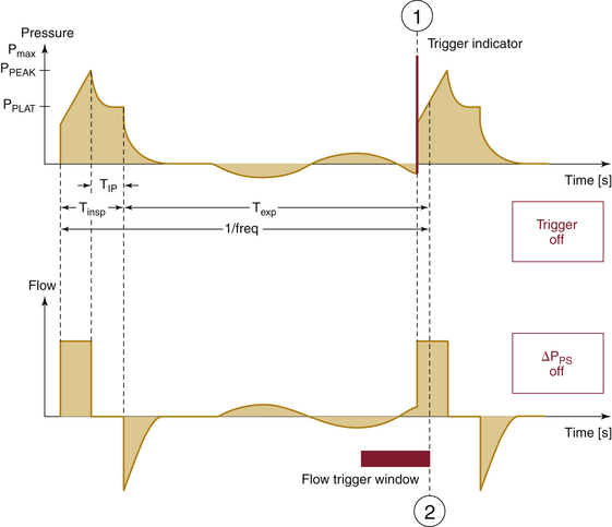
FIGURE 6-21 Graph of pressure and flow traces for synchronized intermittent mandatory ventilation. Shown are time-pressure (upper) and time-flow (lower) representations. The observational window can use pressure or flow as a monitor of airway status. (Courtesy Dräger Medical, Telford PA.)
This observation window is not a trigger as seen in ACV or PSV; it is a sensor or monitor. The rationale revolves around the volume of gas expected in the airway during the window period. Low pressure and flow changes from baseline within the window period are associated with small airway volumes, and high pressure and flow changes from baseline during the window period are associated with large volumes. The delivery of a mandatory breath at the beginning of the cycle is safe if there is no significant gas volume in the airway. Delivery of a mandatory breath when a large gas volume is already in the airway places the patient at significant risk for barotrauma. When airway volumes are predictably high, the ventilator delivers the mandatory breath at the end of the respiratory interval. Although there is still a chance that breath stacking will occur at the end of the interval, breath stacking rarely occurs in this mode.
When a patient is on SIMV mode, it is difficult to determine the ventilator mode simply by observation. Because breaths can occur at the beginning or end of a respiratory interval, consecutive mandatory breaths may appear at intervals of long, intermediate, or short duration. Consecutive breaths may be initiated in four configurations: 1) beginning and end (long interval), 2) beginning and beginning (intermediate interval), 3) end and end (intermediate interval), and 4) end and beginning (short interval). SIMV mode appears the same as VCV or PCV when the patient does not make a respiratory effort.
Spontaneous Breathing Without Assistance or Support
All anesthesia ventilators allow spontaneous ventilation without mechanical assistance or support. The use of a ventilator in this fashion allows continuous monitoring of respiratory parameters while the patient generates all the work of breathing. Pressure, volume, flow, and respiratory rate can be monitored for all phases of anesthetic management in which the patient spontaneously breathes. In steady state, only two possible conditions can occur to change respiratory parameters: the airway pressure can start and end at atmospheric pressure, the so-called flow-by mode, or positive pressure can be applied to the airway during breathing, the continuous positive airway pressure (CPAP) mode.
CPAP mode is more easily accepted in the ICU as a mode of breathing because it can be set on the ventilator. The CPAP number represents the airway pressure between exhalation and inhalation, when the gas flow within the airway is zero. When the patient inhales, a relative negative pressure is created within the airway compared with the set CPAP number, and gas flows into the patient. On exhalation, the airway pressure exceeds the set CPAP number and causes airway gases to exit the patient. As such, the airway pressure appears to oscillate around the set CPAP number.
On the anesthesia machine, the CPAP setting is manually dialed with the adjustable pressure-limiting (APL) valve. (Modern valves are now pressure regulators and not pressure resistors.) End exhalation occurs as a fleeting moment on an anesthesia monitor between exhalation and inhalation, which is why most clinicians use peak exhalation pressures as a guide for CPAP when administering an anesthetic. Unless there is vigorous exhalation, the difference between peak exhalation pressure and the end exhalation pressure is only 1 to 2 cm H2O. In the ICU, the end exhalation pressure correlates to the set CPAP because the ICU ventilators are able to distinguish between peak exhalation pressure and end exhalation pressure.
Confusion regarding this mode commonly occurs if a subatmospheric pressure is generated during a vigorous inhalation. The trough pressure created at maximal inspiratory effort is confused with the terminology peak inspiratory pressure, in which the word peak is taken to mean “the highest.” Most clinicians use the term peak to refer to maximal flow or maximal effort. Thus the term peak inspiratory pressure means the highest airway pressure when positive pressure ventilation is used to generate a breath and the lowest airway pressure achieved when spontaneous ventilation occurs.
CPAP during anesthesia may serve in alveolar recruitment and facilitate oxygenation. On the pressure-volume curve, CPAP can shift function to the right and allow the best compliance characteristics of the lung to be manifested. In doing so, patients may be able to generate a better tidal volume for a given generated pressure. However, as with all conditions that increase airway pressure, CPAP increases intrathoracic pressure, which in turn decreases venous return and cardiac output. Also, patients with obstructive lung physiology may incur air trapping and worsening oxygenation and ventilation. Flow-by mode is generally used immediately before extubation; and use at this time allows the clinician to judge native respiratory effort and respiratory parameters most consistent with successful extubation.
Other Modes of Ventilation
High-frequency ventilation (HFV) generally is defined as 60 to 3000 breath cycles/min but has been technically defined by the FDA as a rate exceeding 150 breath cycles/min.36,37 HFV may be classified into three types. The first, high-frequency positive-pressure ventilation (HFPPV), uses a nasotracheal tube or catheter without side holes to insufflate a controlled anesthetic gas mixture. Small tidal volumes and rates of 60 to 120 breaths/min are used, inspiration is active, and exhalation is passive. This technique may require specially designed low-compliance ventilators, although most conventional ventilators can be effectively used in this manner. HFPPV has been used successfully in many types of airway and thoracic surgical procedures and during extracorporeal shock wave lithotripsy.21,38,39 The Datex-Ohmeda 7800 and Dräger ventilators have both been tested under extreme conditions, mimicking ARDS, and were found capable of maintaining minute ventilation fairly well.40
High-Frequency Jet Ventilation
The second type of high-frequency ventilation is high-frequency jet ventilation (HFJV), but it is not discussed here. The third type is high-frequency oscillatory ventilation (HFO). In contrast to the HFJV, HFO uses the highest frequencies, smallest volumes, and an active expiratory phase, through oscillation, using piston pumps or diaphragms that oscillate like loudspeakers. Sinusoidal waveforms are generated with an I:E ratio of 1:1.21 Rates of 400 to 2400 cyles/min are used. Gas exchange at these frequencies and at volumes less than dead space volume depend on diffusion and coaxial airway gas flow. Special ventilators, such as the Sensormedics 3100A (Sensormedics, Yorba Linda, CA), oscillate a diaphragm by electromagnetic impulses. Precise amounts of potent inhaled volatile anesthetics can be delivered via a vaporizer proximal to the ventilator and require minimal entrainment of room air. Advantages of these techniques include 1) low airway pressures for bullous lung diseases, 2) small excursions for peripheral lung surgery, and 3) prevention of barotrauma in neonates. OR experience with these ventilators is limited.
Airway Pressure-Release Ventilation
Airway pressure-release ventilation (APRV) is a newcomer to the ventilator mode arena, although similar modes are already used as a bridge mode of ventilation for nonintubated patients, as seen in the use of bilevel positive airway pressure (BiPAP). During the inspiratory cycle, high-pressure CPAP (Phigh) is delivered for a preset period of inspiratory time (TI). During inspiration, the patient’s efforts to breathe can be observed as deflections in the pressure and flow monitors.
At this point, APRV looks like an anesthesia circuit set at high-pressure CPAP using the APL valve; satisfactory alveolar recruitment is achieved, but ventilation depends on the patient’s ability to generate a tidal volume. If the ventilator does not release the airway pressure often enough, carbon dioxide concentrations would rise and cause predictable effects.
Once the inspiratory time has been achieved, exhalation occurs, and airway pressure is released to a lower pressure (Plow) for the time of exhalation (Te). The lower airway pressure is PEEP if the exhalation airway pressure is supraatmospheric. However, if the exhalation pressure is equal to atmospheric pressure, it is the Plow. To avoid confusion, the term Plow is used to refer to the exhalation pressure. Carbon dioxide is removed from the patient during exhalation. Clinically, the inspiratory time is greater than the exhalation time. As such, IRV is a functional characteristic of this mode of ventilation, and I:E ratios as high as 8:1 are commonly observed. More attention is applied to the exhaled tidal volume and its relationship to indicators of satisfactory ventilation.
As with some other modes of ventilation, APRV has not been considered clinically useful in the OR. Scientific literature advocating the superiority of this mode of ventilation for patients undergoing surgery is lacking, and use of this mode of ventilation for patients undergoing surgical procedures in the OR currently is experimental or is reserved for pathophysiologic outliers.
Current Designs of Anesthesia Ventilators
The traditional anesthesia machine—composed of the gas mixer, vaporizer, ventilator, and circuit—has evolved to the anesthesia workstation. As such, the workstation as a unit is designed to 1) monitor patients for important parameters, 2) sound an alarm when dangerous events occur, 3) serve as an integrated anesthesia delivery device, and 4) record the significant events of the anesthetic for the permanent record.
Recent events in anesthesia workstation sales have resulted in a merging of manufacturer product lines. In the process of this merging, workhorse technologies have surfaced, and although variation and expression in ventilator design may be reduced, reliable and predictable ventilator products are now in the marketplace. Two major manufacturers are presented to demonstrate current ventilator designs.
GE Healthcare joined forces with Datex-Ohmeda in the production of workstations using the 7100 series of ventilators and their newest ventilator, the 7900 Smartvent. GE Healthcare markets these ventilators in many workstation product lines, including the Aisys, Aespire, Avance, and Aestiva Carestations.
Dräger Medical, the producer of the E-vent piston ventilator, is currently a joint project of the Dräger and Siemens companies. Dräger Medical uses its piston ventilator in the Apollo Anesthesia Workstation and Fabius lines, which include the GS Premium, MRI, Tiro, and Tiro M.
When examining a specific ventilator among these product lines, the actual ventilator design and function do not appear to change. The changes in the product line models occur in the breathing circuit design and sensor systems. The breathing circuit design changes as new ventilators emerge, improvements in materials are applied, and philosophies on safety, oxygenation, ventilation, and lung protection are recognized. The application of sensors for pressure and flow at various locations throughout the circuit ensures proper function of the system, monitoring of critical events, and feedback systems to improve ventilator performance. As circuit design and sensor systems change, appropriate changes in microprocessor control must occur. For proper function, different hardware and/or software may be required to integrate the vast amount of information for the various configurations.
Lastly, workstation manufacturers offer various displays of important parameters. An analog survivor, the circuit pressure strain gauge, allows continuous direct circuit pressure monitoring without the use of electricity. Most displays now offer combinations of numeric and digital waveform information (parameter vs. time). As an example, the airway pressure-versus-time waveform, numeric tidal volume, and numeric peak airway pressure are displayed as a standard for most product lines. Digital parameters allow trending and waveform analysis. The most basic software packages—those set by safety, industry standard, and legislation— usually are included in the base price of the workstation. In addition, advanced spirometry loops have been available for many years. The complexity of the monitoring, trending, alarming, and waveform analysis is a determinant of the cost of the analysis software package.
7900 Smartvent
The Datex-Ohmeda 7900 Smartvent is designed around the bag-in-a-bottle configuration. As such, two different gas circuits are used in ventilation. When the ventilator is in use, the driving-gas circuit uses high-pressure air or oxygen (flow-generator classification) to squeeze a visible ascending bellows; this bellows is housed in a clear, hard plastic case and is under microprocessor control. The gas contained inside the bellows is part of the patient circuit.
When the bellows is pushed, the gas contained within it is pushed through the carbon dioxide adsorber. This gas mixes with the fresh gas flow just prior to entering the inspiratory limb of the patient circuit on its way to the patient (Fig. 6-22). On exhalation, used gases pass down the expiratory limb of the patient circuit and back to the bellows. Unidirectional valves, just prior to the inspiratory limb and immediately following the exhalational limb of the patient circuit, ensure one-way gas flow through the entire patient circuit (Fig. 6-23).
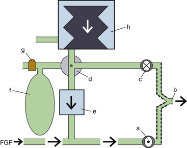
FIGURE 6-22 Ventilator-delivered breath in inspiration with the Datex-Ohmeda 7900 ventilator (GE Healthcare, Waukesha, WI) circuit (simplified schematic). While the bag/ventilator switch (d) is in the “ventilator” position, the ventilator (h) is activated. Gases within the ventilator bellows are pushed into the ventilator circuit, closing the exhalation valve (c). These gases pass antegrade through the CO2 absorber (e) and combine with the fresh gas flow (FGF). The mixed gases enter the patient circuit through the inspiratory valve (a) to the patient (b). A higher pressure within the patient to machine circuit closes the exhalation valve (c). f, reservoir bag; g, adjustable pressure limiting value.
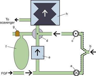
FIGURE 6-23 Ventilator-delivered breath in exhalation with the Datex-Ohmeda 7900 ventilator (GE Healthcare, Waukesha, WI) circuit (simplified schematic). While the bag/ventilator switch (d) is in the “ventilator” position, the ventilator (h) is activated. Exhaled patient gases (b) close the inspiratory valve (a) and open the exhalation valve (c). Because the inspiration valve is closed, the fresh gas flow (FGF) is diverted retrograde through the CO2 absorber (e). Mixed gases from the FGF and exhaled gases reinflate the ventilator bellows. Excess gas volume is eliminated through a low-pressure pop-off valve within the ventilator assembly to the gas scavenger system. f, reservoir bag; g, adjustable pressure limiting value. (From Explore the anesthesia system, 1996, Ohmeda [now GE Healthcare, Waukesha, WI], pp 6-45.)
The drive gas can be either oxygen or air. This is set up by the service technician when the ventilator is first installed; the gas comes from either the anesthesia machine pipeline or cylinder supply. If a cylinder is used to power the ventilator, it will use up the gas supply faster than would be predicted from the flowmeter settings. The gas being used to drive the ventilators can be seen by pushing the menu key, selecting setup/calibration, then selecting about ventilator.
During exhalation, both exhalational gases from the patient and absorber gases being pushed retrograde by the fresh gas flow fill the bellows. Also during exhalation, when the bellows is filled and the pressure exceeds 2.5 cm H2O, an internal mechanical valve within the bellows assembly opens and redirects the patient circuit gas to the scavenger system (Fig. 6-24). This must occur because gas is constantly being added to the system by the fresh gas flow.
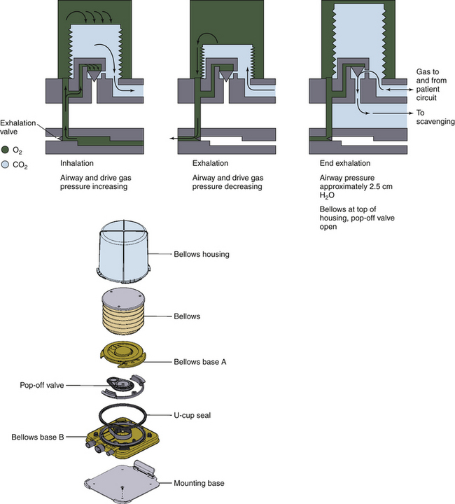
FIGURE 6-24 Bellows pop-off valve. Figure demonstrates the scavenging of excess airway gases at late exhalation when pressure inside the bellows exceeds 2.5 cm H2O. (From Explore the anesthesia system, 1996, Ohmeda [now GE Healthcare, Waukesha, WI], pp 6-18.)
Basic ventilator modes available include spontaneous breathing (Figs. 6-25 and 6-26) with or without CPAP and VCV. Certain GE Healthcare products may include PCV, SIMV, and PSV (Pro series) modalities as a standard build or as an option. The SIMV mode is a volume mode with the ability to deliver PSV between breaths. Interestingly, the PSV Pro mode has an apnea back-up mode using SIMV in pressure mode, with the ability to conduct PSV breaths between controlled breaths. Once the apnea alarm has been triggered, SIMV (pressure) with PSV will be delivered until the PSV Pro mode is selected through the menu system or the ventilator is turned off and on by using the ventilator/bag selector. This ventilator is equipped with electronic PEEP.
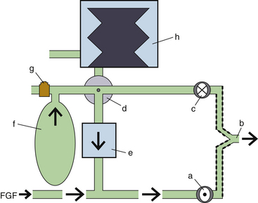
FIGURE 6-25 Spontaneous breath in inspiration with the Datex-Ohmeda 7900 ventilator (GE Healthcare, Waukesha, WI) circuit (simplified schematic). While the bag/ventilator switch (d) is in the “bag” position, the machine circuit has access to the reservoir bag (f) and the adjustable pressure-limiting (APL) valve (g). The ventilator (h) is deactivated. A patient-initiated breath (b) opens the inspiratory valve (a) and closes the exhalation valve (c). Gases within the reservoir bag are pulled antegrade through the CO2 absorber (e). These gases mix with the fresh gas flow (FGF) while traveling to the patient (b).
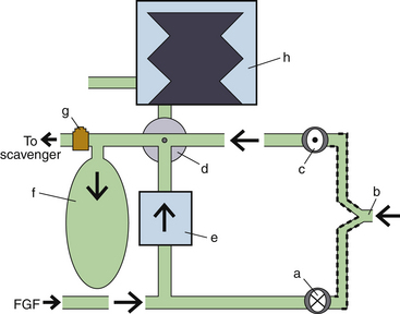
FIGURE 6-26 Spontaneous breath in exhalation with the GE Datex-Ohmeda 7900 ventilator (GE Healthcare, Waukesha, WI) circuit (simplified schematic). While the bag/ventilator switch (d) is in the “bag” position, the machine circuit has access to the reservoir bag (f) and the adjustable pressure-limiting (APL) valve (g). The ventilator (h) is deactivated. Exhaled patient gases (b) close the inspiratory valve (a) and open the exhalation valve (c). Because the inspiratory valve is closed, fresh gas flow (FGF) is diverted retrograde through the CO2 absorber (e). The mixed gases from the FGF and exhalation fill the reservoir bag. Excess gas volume is removed from the system by the APL valve.
The 7900 Smartvent is also capable of providing tidal volume compensation from circuit feedback. This helps provide consistent delivery of set tidal volumes by automatically adjusting for changes in fresh gas flows; changing lung compliance; small system leaks; or compression losses in the ventilator, patient circuit, absorber, or bellows. The manufacturer claims accurate volume delivery to 20 mL of set tidal volume when available. When present, the compensation requires a few breaths to reach a compensated volume.
The set tidal volume range is 20 to 1500 mL for VCV and SIMV (volume) modes. Users may set an inspiratory pause for modes with volume breaths. In PCV modes, inspired pressure can be set from 5 to 60 cm H2O and from 2 to 40 cm H2O in PSV modes. For VCV and PCV, the respiratory rate can be set from 4 to 100 breaths/min, and the I:E ratio may be adjusted from 2:1 to 1:8 in increments of 0.5. The inspiratory time may be set to 0.2 to 5 seconds for SIMV and PSV Pro modes. In addition, the flow trigger for PSV Pro can be adjusted. In SIMV modes the observational window period, called a trigger window by GE Healthcare, can be adjusted.
GE Healthcare claims less than a 7% and 9% deviation in tidal volume delivery and monitoring, respectively, when set tidal volumes are above 210 mL. Accuracy is improved in delivery and monitoring at lower set tidal volumes. Pressure delivery and monitoring is accurate to ±3 and ±2 cm H2O, respectively, and delivery of PEEP is accurate to ±1.5 cm H2O.
Among the common adjustable alarms are tidal volume (low and high) and minute volume (low and high). In addition, four pressure alarms include high pressure, low pressure, negative pressure, and sustained pressure; an apnea alarm and a FiO2 alarm (low and high) are also adjustable. The priorities of ventilator alarms are low, medium, and high. Low-priority alarms are sounded only once, as a single tone; as priority increases, multiple alarm tones are repeated until disabled by the user or the problem resolves.
Condensation of circuit humidity could foul the normal function of the variable-orifice flow sensors located at the proximal inspiratory and distal exhalation limb of the patient circuit, especially if the clinician does not interpose a disposable heat and moisture exchanger (HME). This problem is magnified in a cold OR; such a malfunction may be heralded by various flow senor alarms, such as check flow, exp reverse flow, insp reverse flow, and Vte > Insp Vt. A new flow sensor design purportedly minimizes this condensation problem. In addition, holes or perforations in the ventilator bellows may cause the entrainment of driving gas into the bellows. The resulting dilution of the anesthetic agent can cause patient awareness, and the use of air as the drive gas may cause the unintentional delivery of a gas mixture with a lower than expected oxygen concentration, which could lead to hypoxia. Many clinicians appreciate being able to see the ventilator bellows because it affords early detection of ventilator malfunction, disconnect, and circuit leak.
E-vent
The E-vent ventilator deviates from common ventilator designs of the past 40 years by the use of a piston and electrical motor to generate airway pressures, gas flows, and tidal volumes. This system is used in all of the current Dräger Medical workstations. As this piston ventilator produces pressures close to, or only moderately above, airway pressure to move gases, it fits the pressure generator classification of ventilators. Again, its classification as a pressure generator does not exclude its ability to provide reliable, constant flow at fixed volumes (VCV) or constant pressure (PVC) ventilation. Once calibrated, the movements of the piston within the cylinder are well defined and allow precise calculations of the delivered tidal volume, especially in low FGF states.
The ventilator is typically located in front of the unidirectional inspiratory valve of the inspiratory limb of the circuit. The reported advantage of this comes from decreasing the compressible gas volume on the inspiratory side of the circuit. In doing so, the accuracy of the delivered ventilator breath is increased. When the ventilator is cycled, the emptying piston ventilator closes a fresh gas decoupler upstream from the ventilator, which causes two separate events to occur. First, the piston gases are pushed into the inspiratory limb of the circuit to the patient, while the computer closes the PEEP/Pmax value in the expiratory circuit. At the same time, the closed fresh gas decoupler valve diverts FGF through the carbon dioxide absorber retrograde to the reservoir bag. The reservoir bag is not adjusted by the APL valve because this is automatically bypassed in the mechanical ventilation mode (Fig. 6-27). On exhalation, gases from the patient and exhalation limb exit the circuit and pass through the unidirectional expiratory valve and PEEP/Pmax valve. These gases combine directly with the residual and fresh reservoir bag gas before passing over the CO2 absorber with retraction of the piston. Thus, the mixed gases from the reservoir bag, CO2 absorber, and fresh gas inflow all join together as the piston cylinder fills (Fig. 6-28).
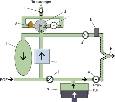
FIGURE 6-27 Ventilator-delivered breath in inspiration with the Apollo and Fabius ventilator (Dräger Medical, Telford, PA) circuits (simplified schematic). While the ventilator switch is on, the ventilator piston (h) is activated. In addition, the adjustable pressure-limiting (APL) valve (g) is deactivated, and the APL bypass valve (i) is actively opened. This functionally diverts (d) excess circuit gas across the APL bypass valve toward the scavenger nonreturn valve (l). The ventilator piston empties gas contents into the inspiratory limb, closing the fresh gas decoupling valve (j) and opening the inspiratory valve (a). This allows gas to be pushed into the lungs (b). During inspiration, the PEEP/Pmax valve (k) is closed electronically, preventing inspiratory gas from passing across the expiratory valve (c). If the patient circuit exceeds the set pressure maximum, the PEEP/Pmax valve opens to release the excess airway pressure. While the fresh gas decoupler valve is closed, fresh gas flow (FGF) is diverted retrograde through the CO2 absorber (e), filling the reservoir bag (f). When the reservoir bag is filled, excess pressure causes excess gas volume to pass out of the system through the APL bypass valve and the scavenger nonreturn valve.
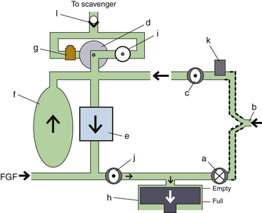
FIGURE 6-28 Ventilator-delivered breath in exhalation with the Apollo and Fabius ventilator (Dräger Medical, Telford, PA) circuits (simplified schematic). While the ventilator switch is on, the ventilator piston (b) is activated. In addition, the adjustable pressure-limiting (APL) valve (g) is deactivated, and the APL bypass valve (i) is actively opened. This functionally diverts (d) circuit gas across the APL bypass valve toward the scavenger nonreturn valve (l) whenever excess gas fills the reservoir bag (f). On exhalation, gas from the lungs (b) is first expelled passively into the ventilator circuit across the expiratory valve (c) into the reservoir bag by the active opening of the PEEP/Pmax valve (k). (Note that the PEEP/Pmax valve would only partially open if PEEP were desired.) Exhalation closes the inspiratory valve (a). Next, the ventilator piston moves from the empty position to the full position, opening the fresh gas decoupling valve (j), and mixed gases from the expiratory limb and reservoir bag are pulled antegrade through the CO2 absorber (e). This gas mixes with the fresh gas flow (FGF) while filling the piston.
The most basic E-vent ventilator and workstation are provided with a spontaneous mode of breathing (Figs. 6-29 and 6-30) with or without CPAP and VCV. Some models offer as standard or optional modes PCV, PSV, and SIMV (volume) with PSV. The supported breathing mode allows support by pressure (PSV) or volume breaths (AV).
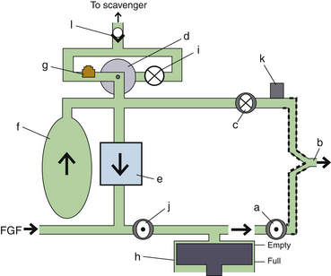
FIGURE 6-29 Spontaneous breath in inspiration with the Apollo and Fabius ventilator (Dräger Medical, Telford, PA) circuits (simplified schematic). While the ventilator switch is off, the ventilator piston (h) is deactivated. The ventilator piston stays at the empty, top position (default). In addition, the adjustable pressure-limiting (APL) bypass valve (i) is deactivated (default is closed), and the APL valve (g) is activated. This functionally diverts (d) excess circuit gas across the APL valve toward the scavenger nonreturn valve (l). A breath initiated by the patient (b) opens the inspiratory valve (a) and closes the expiratory valve (c). Gases from the reservoir bag (f) are pulled antegrade through the CO2 absorber (e) to join the fresh gas flow (FGF) while traversing the now open fresh-gas decoupling valve (j).
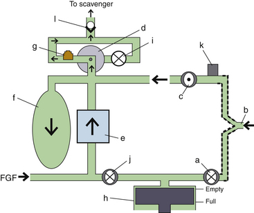
FIGURE 6-30 Spontaneous breath in exhalation with the Apollo and Fabius ventilator (Dräger Medical, Telford, PA) circuits (simplified schematic). While the ventilator switch is off, the ventilator piston (h) is deactivated; the ventilator piston stays at the empty, top position (default). In addition, the adjustable pressure-limiting (APL) bypass valve (i) is deactivated (default is closed), and the APL valve (g) is activated. This functionally diverts (d) excess circuit gas across the APL valve toward the scavenger nonreturn valve (l). Exhaled gas from the patient (b) opens the expiratory valve (c) and closes the inspiratory valve (a). Exhaled gas joins fresh gas flow (FGF) traveling retrograde through the CO2 absorber (e). The mixed gas fills the reservoir bag (f). When the reservoir bag is filled, excess pressure closes the expiratory valve and allows excess gas volume to pass out of the system through the APL valve and the scavenger nonreturn valve.
The fresh gas decoupler valve affords the ventilator volume and pressure delivery without interference from the FGF, which improves ventilator accuracy. Some workstations are equipped with an automated start-up procedure that checks the compliance of the circuit before use. In addition, some models can adjust initial ventilator settings based on patient age and weight.
The E-vent ventilator can provide respiratory frequencies from 3 to 80 breaths/min, and the I:E ratio can be adjusted from 1:4 to 5:1. Tidal volumes between 20 and 1400 mL are attainable. In pressure modes, peak pressure can be adjusted to 70 cm H2O, and the inspiratory time window for SIMV can vary from 0.3 to 6.7 seconds. The inspiratory flow in pressure mode can achieve 150 L/min in some workstations; the flow trigger for PSV can be adjusted from 0.3 to 15 L/min, and maximum deliverable PEEP is 20 cm H2O. Similar standard alarms are provided compared with the previous manufacturer; however, tones and screen warnings may differ.
An advantage over the gas-driven bellows configuration described above is the motor-driven piston. Because the motor is electrically driven, no oxygen or air is required for its function, which can reduce the costs of compressed and wasted gases. However, the ventilator can fail as a result of worn motor parts. The ventilator piston returning to the filled position could cause negative pressure in the system, with a flat reservoir bag, were it not for negative-pressure entrainment valves. Also, if the reservoir bag were to be torn or removed, or if system leaks occurred, room air could be entrained and thereby dilute the gases to be delivered, causing hypoxia and patient awareness. Some clinicians dislike the workstation design that encloses the ventilator piston within the machine because it occludes the visible function of the ventilator; however, new software displays have been designed that enhance the “visibility” of the piston by revealing its function.
Ventilator Concerns with Utilization
General Concerns with Airway Pressure
Complications of mechanical ventilation have been reviewed by Keith and Pierson.41 One problem associated with the use of an anesthesia ventilator is overpressurization of the airway, which can occur in several situations: 1) when the patient coughs against the ventilator, 2) when the ventilator’s settings are excessive for the first breath, or 3) when the oxygen flush button is depressed during the inspiratory phase. A pressure limit control is available on contemporary anesthesia ventilators; this should be appropriately set because the internal overpressure protection devices may not open until a pressure high enough to cause a pneumothorax is reached. Problem 3 is eliminated by fresh gas–decoupled circuitry.
Some problems arise even during proper operation of the ventilator, such as 1) hypothermia and drying of secretions, usually avoided by using disposable HMEs; 2) hypercarbia or hypocarbia as a result of setting the ventilator incorrectly; 3) hypotension secondary to excessive tidal volume, excessive minute ventilation, or excessive PEEP or auto-PEEP, all of which can reduce preload; 4) barotrauma from excessive transpulmonary pressure; 5) hidden airflow obstruction, particularly from mucous plugging, mainstem intubation, tracheal tube cuff herniation, or bronchospasm; 6) hypoxemia from inadequate ventilator settings; and 7) electromagnetic interference with electronically controlled microprocessors.41
As a general rule, when machine malfunction impairs the safe delivery of anesthetic gases, the patient should be immediately disconnected from the anesthesia machine, and a back-up ventilation system should be used instead.
Cross-Infection
Infection risk related to the anesthesia ventilator and circuit was evaluated in the early 1980s. Several authors have studied the risk of cross-infection arising from the use of ventilators and anesthesia circuits. Cross-infection cases have been reported in which the repeated use of the same piece of airway equipment transferred infection among patients.42 Carbon dioxide absorbers cannot be regarded as a barrier to the transmission of bacteria. Indeed, bacteria such as Pseudomonas have been cultured from soda lime absorbers.43 Nevertheless, with the older type of nondisposable circuits, adequate infection control was achieved by washing with suitable decontamination fluids.44 The subsequent widespread introduction of disposable circuits has obviated the need for such decontamination; bacteria are not disseminated during quiet breathing, nor does the machine or circuit disseminate organisms.45,46
The concern caused by human immunodeficiency virus (HIV) and the even greater risk posed by hepatitis B or C transmission warrant vigilance about controlling cross-contamination in all aspects of anesthesia care. Precautions that prevent cross-contamination appear to offer appropriate safety for airway equipment and anesthesia delivery systems. The use of disposable circuits appears to afford patients adequate safety, although actual sterility is hard to achieve. The GE Healthcare bellows and canister system is easily disassembled and autoclavable; however, the absorber manifold is interposed between the circuit and bellows. Similar to other anesthesia circle breathing systems, it cannot be cleaned effectively without disassembly by trained technicians. The entire Dräger breathing manifold and system are easily removed and autoclavable, which has recently been recommended for the preparation of the machine in patients susceptible to malignant hyperthermia.
Check-Out Procedures
The 1993 check-out recommendations from the United States Food and Drug Administration (FDA)47 should be used as a generic checklist for ascertaining the proper function of a ventilator. Specific manufacturer recommendations should always be consulted. The FDA list states that backup manual ventilation must be immediately available and must be tested. These resuscitators typically have a one-way valve that must be properly installed and competent to provide positive-pressure ventilation. The scavenger system and ventilator relief valve (pop-off valve) should be tested together to verify that excess gas will be released once the bellows is full to prevent any distension or sustained pressure. Then, with minimal or no flow, the bellows should remain filled to ascertain a proper seal of the relief valve, proper seating of the bellows, and no holes in the bellows. Next, when the ventilator is activated with a test lung (a second reservoir bag at the patient “Y”) and no FGF, the bellows should not lose volume. If it does, the ventilator relief valve may not be sealing under pressure. Furthermore, the volume delivered and motion of the test lung should be appropriate for the set parameters, or a leak in the drive gas circuit should be considered. In the active test mode, external pressure applied to the test lung should appropriately activate the pressure limit safety feature and high-pressure alarm.
Since the 1993 FDA recommendations were made, new check-out procedures have been required to adapt to the changing anesthesia delivery systems. Further, a single check-out procedure is no longer applicable to the various equipment designs. Updated recommendations were developed in 2008 by a multidisciplinary subcommittee of the American Society of Anesthesiologists (ASA) Committee on Equipment and Facilities.48 The check-out design guideline is also supported as educational information by the FDA’s Office of Device Evaluation. Sample check-out procedures have been submitted and approved for inclusion in the ASA library by the ASA Committee on Equipment and Facilities.49
Intraoperative Procedures
Vigilance should be maintained whenever a ventilator is in operation. When mechanical ventilation is selected in older workstations, it is essential to change from manual to mechanical ventilation on the ventilator selection switch. The ventilator and pressure limit must be appropriately set for each patient, and the first ventilator-delivered breath must be observed, carefully watching for chest expansion, proper cycling, peak pressure, I:E ratio, airway pressure waveform, plateau pressure, inspiratory pause, and tidal volume before and after adjusting the FGF. Is the bellows compression complete, and does it completely return during exhalation? Is the inspiratory flow adequate to meet ventilatory settings? Once ventilation is established, reset the minute volume and minimum airway pressure alarms, the pressure limiter, PEEP, and the peak airway pressure alarm according to the patient’s unique parameters. Listen to breath sounds, despite capnography, to see if they are coincident with, and appropriate for, ventilator sounds. Follow end-tidal carbon dioxide and pulse oximetry as measures of ventilation, breathing circuit valve function, and proper alveolar expansion.
References
1. Baker A.B. Early attempts at expired air respiration, intubation and manual ventilation. In: Atkinson R.S., Boulton T.B., eds. The history of anaesthesia. London: Royal Society of Medicine; 1987:372–374.
2. Gordon A.S. History and evolution of modern resuscitation techniques. In: Gordon A.S., ed. Cardiopulmonary resuscitation conference proceedings. Washington, DC: National Academy of Sciences; 1966:7–32.
3. Vesalius A. De humani corporis fabrica libri septem. Basileae: Ex Off. Ioannis Oporini; 1543.
4. Mushin W.W., Rendell-Baker L. The principles of thoracic anaesthesia. Oxford: Blackwell; 1953. pp 28–30
5. O’Dwyer J. Fifty cases of croup in private practice treated by intubation of the larynx, with a description of the method and of the dangers incident thereto. Med Rec. 1887;32:557–561.
6. Fell G.E. Forced respiration. JAMA. 1891;16:325–330.
7. Hochberg L.A. Thoracic surgery before the 20th century. New York: Vantage Press; 1960. 684–697
8. Tuffier T., Hallion L. Intrathoracic operations with artificial respiration by insufflation. C R Soc Biol (Paris). 1896;48:951.
9. Matas R. Artificial respiration by direct intralaryngeal intubation with a new graduated air-pump, in its applications to medical and surgical practice. Am Med. 1902;3:97–103.
10. Drinker P., Shaw L. An apparatus for the prolonged administration of artificial respiration. J Clin Invest. 1929;7:229.
11. Mushin W.W., Rendell–Baker L., Thompson P.W., et al. Automatic ventilation of the lungs. Oxford, UK: Blackwell Scientific; 1980.
12. Magill I.W. Development of endotracheal anaesthesia. Proc R Soc Med. 1928;22:83–88.
13. Lassen H.C.A. A preliminary report on the 1952 epidemic of poliomyelitis in Copenhagen with special reference to the treatment of acute respiratory insufficiency. Lancet. 1953;1:37–41.
14. Bjork V.O., Engstrom C.G. The treatment of ventilatory insufficiency after pulmonary resection with tracheostomy and prolonged artificial ventilation. J Thorac Surg. 1955;30:356–367.
15. Frumin M.J., Epstein R.M., Cohen G. Apneic oxygenation in man. Anesthesiology. 1959;20:789–798.
16. Chatburn R.L. Classification of mechanical ventilators. In: Tobin M.J., ed. Principles and practice of mechanical ventilation. New York: McGraw-Hill, 1994.
17. MacIntyre N.R. New modes of mechanical ventilation. Clin Chest Med. 1996;17:411–421.
18. Slutsky A.S. Mechanical ventilation. American College of Chest Physicians’ consensus conference. Chest. 1993;104:1833–1859.
19. Feihl R., Perret C. Permissive hypercapnia: how permissive should we be? Am J Respir Crit Care Med. 1994;150:1722–1737.
20. Marcy T.W. Inverse ratio ventilation. In: Tobin M.J., ed. Principles and practice of mechanical ventilation. New York: McGraw-Hill; 1994:319–331.
21. Schwartz D.E., Katy J.A. Delivery of mechanical ventilation during general anesthesia. In: Tobin M.J., ed. Principles and practice of mechanical ventilation. New York: McGraw-Hill, 1994.
22. Acute Respiratory Distress Network. Ventilation with lower tidal volumes as compared with traditional tidal volumes for acute lung injury and the acute respiratory distress syndrome. N Engl J Med. 2000;342(18):1301–1308.
23. Schultz M.J., Haitsma J.J., Slutsky A.S., Gajic O. What tidal volumes should be used in patients without acute lung injury? Anesthesiology. 2007;106(6):1226–1231.
24. ASTM. Standard specification for ventilators intended for use during anesthesia, F1101–90. West Conshohocken, PA: American Society for Testing and Materials; 1990.
25. Marini J.J., Ravenscraft S.A. Mean airway pressure: physiologic determinants and clinical importance. Part 1. Physiologic determinants and measurements. Crit Care Med. 1992;20:1461–1472.
26. Marini J.J., Ravenscraft S.A. Mean airway pressure: physiologic determinants and clinical importance. Part 2. Clinical implications. Crit Care Med. 1992;20:1604–1616.
27. McKibben A.W., Ravenscraft S.A. Pressure-controlled and volume-cycled mechanical ventilation. Clin Chest Med. 1996;17:395–410.
28. Marks J.D., Schapera A., Kraemer R.W., Katz J.A. Pressure and flow limitations of anesthesia ventilators. Anesthesiology. 1989;71:403–408.
29. Marks J.D., Katz J.A., Schapera A., Kraemer R.W. Evaluation of a new operating room ventilator: the Ohmeda 7810. Anesthesiology. 1989;71(3A):A463. (abstract)
30. ANSI. American National Standard for Breathing Machines for Medical Use, ANSI Z79.7. New York: American National Standards Institute; 1976.
31. Ohmeda 7900 Ventilator operations and maintenance manual. Madison, WI: Ohmeda, The BOC Group; 1996.
32. Salzano J.V., Camporesi E.M., Stolp B.W., Moon R.E. Physiologic responses to exercise at 47 and 66 ATA. J Appl Physiol. 1984;57:1055.
33. Nunn J.F., ed. Nunn’s applied respiratory physiology, ed 4, Oxford/Boston: Butterworth-Heinemann, 1993.
34. Mielke L., Breinbauer B., Kling M., et al. The use of the Servo 900 B for ventilation in hyperbaric chambers [abstract]. Anesth Analg. 1996;82:S315.
35. Thomas G., Brimacombe J. Function of the Dräger Oxylog ventilator at high altitude. Anaesth Intens Care. 22, 1994. 276–228
36. Rouby J.J., Viars P. Clinical use of high frequency ventilation. Acta Anaesthesiol Scand Suppl. 1989;33:134–139.
37. Majewski A., Telmanik S., Arrington V. High frequency oscillatory ventilation. Va Med Q. 1994:230–232. Fall
38. Malina J.R., Nordström S.G., Sjöstrand U.H. Wattwil, LM: Clinical evaluation of high-frequency positive-pressure ventilation (HFPPV) in patients scheduled for open-chest surgery. Anesth Analg. 1981;60:324–330.
39. Heres E.K., Shulman M.S., Krenis L.J., Moon R. High-frequency ventilation with a conventional anesthetic ventilator during cardiac surgery. J Cardiothorac Vasc Anes. 1995;9:63–65.
40. Tessler M.J., Ruiz-Neto P.P., Finlayson R., Chartrand D. Can anesthesia ventilators provide high-frequency ventilation? Anesth Analg. 1994;79:563–566.
41. Keith R.L., Pierson D.J. Complications of mechanical ventilation: a bedside approach. Clin Chest Med. 1996;17:439–451.
42. Walter C.W. Cross-infection and the anesthesiologist, twelfth annual Baxter-Travenol lecture. Anesth Analg. 1974;53:631–644.
43. Dryden G.E. Uncleaned anesthesia equipment. JAMA. 1975;233:1297–1298.
44. Nielsen H., Jacobsen J.B., Stokke D.B., et al. Cross-infection from contaminated anaesthetic equipment. Anaesthesia. 1980;35:703–708.
45. du Moulin G.C., Hedley-Whyte J. Bacterial interactions between anesthesiologists, their patients, and equipment. Anesthesiology. 1982;57:37–41.
46. du Moulin G.C., Saubermann A.J. The anesthesia machine and circle system are not likely to be sources of bacterial contamination. Anesthesiology. 1977;47:353–358.
47. Morrison J.L. FDA Anesthesia Apparatus Checkout Recommendations. American Society of Anesthesiologists Newsletter. 1993;1994(58):25–28.
48. Recommendations for Pre-Anesthesia Checkout Procedures. Sub-Committee of ASA Committee on Equipment and Facilities. 2008. Accessed online at. http://www.asahq.org/clinical/FINALCheckoutDesignguidelines02-08-2008.pdf
49. American Society of Anesthesiologists. Sample checkout procedures. Available at http://www.asahq.org/clinical/checklist.htm.


