Humidification and Filtration
Overview
Under normal physiologic conditions, the upper airway adds heat and moisture to inspired air to prevent drying of lower airway secretions, plugging, and mucosal injury. When dry medical gases bypass the upper airway via an endotracheal tube, the normal heat and moisture exchange function of the upper airway is compromised. This function of the upper airway may be replaced in two ways. First, heat and humidity can be actively added with a heated humidifier; second, and more commonly, heat and moisture may be passively retained using a heat and moisture exchanger (HME).
The upper airway also fulfills the function of filtration and expulsion of particles, including bacteria and viruses, from inspired gas. This is achieved by the mucociliary elevator. The anesthesiologist is responsible for minimizing the risk of infection from inhaled microorganisms. The use of HME filters (HMEFs) protects patients from inhaled microorganisms and also protects the anesthesia circuit from the patient, thereby allowing its reuse.
Physics of Humidity
Water vapor is the gas phase of water. The transition from the liquid to the gas phase is called vaporization, a process that requires energy. The energy required for this process is the latent heat of vaporization, which is 2.27 MJ/kg water.
Humidity describes the amount of water vapor in air. Absolute humidity is the partial pressure of water vapor above its liquid at equilibrium. As such it may be measured in kilopascals (kPa) or other unit of pressure, but in this context it is more commonly referred to as the mass of water in a given volume of air (in milligrams per liter). Evaporation occurs at a constant temperature until a critical mass of water in the air is reached and the air is fully saturated. The pressure of the water vapor at this point is the saturated vapor pressure (SVP) for water, which increases rapidly with increases in temperature (Fig. 7-1).
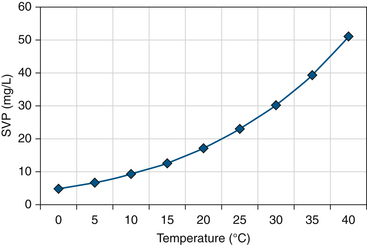
FIGURE 7-1 Saturated vapor pressure (SVP) with temperature. (From Mushin W, Jones P: Physics for the Anaesthetist, ed 4, Boston, 1987, Blackwell Scientific.)
At a given temperature, relative humidity is the relationship of the absolute humidity to SVP, expressed as a percentage. Air at its SVP has 100% relative humidity. Relative humidity equals the mass of water vapor for a given volume of air for a given temperature, and SVP is the mass of water vapor required to fully saturate that volume. For example, fully saturated air at 20° C contains 17 mg/L water and at 37° C contains 44 mg/L water.
As air is heated, its SVP increases. If no further water mass is added, absolute humidity remains the same while relative humidity decreases. For example, air in a typical operating room (OR) at 20° C contains 10 mg/L of water and has approximately 60% relative humidity. If fully saturated air at 20° C is heated to 37° C without adding further water mass, it is said to have 38.6% relative humidity (17 mg/L ÷ 44 mg/L). If fully saturated air is cooled, it will reach its dew point, at which air can no longer support the mass of water vapor, and water undergoes condensation.
Measurement of Humidity
Instruments that measure humidity are referred to as hygrometers. They typically measure relative humidity. If temperature and SVP are known, absolute humidity can be calculated.
Hair Hygrometer
The hair hygrometer makes use of a hair, or a synthetic membrane with similar properties, that lengthens as relative humidity increases. As the hair lengthens, it moves a pointer to create an analog display of relative humidity. If the temperature is known, absolute humidity may be calculated. Hair hygrometers typically are used in operating theatres and neonatal incubators. Hair hygrometers are most accurate at a relative humidity of 30% to 90%; they have a slow response and are of limited use where humidity changes rapidly.
Wet and Dry Bulb Hygrometer
The wet and dry bulb hygrometer consists of two mercury thermometers: one reads a true ambient temperature, and the other has a water-soaked wick around the bulb that, when exposed to a moving stream of air, produces a cooling effect from the loss of the latent heat of vaporization. With dry ambient air, evaporation is increased, resulting in a greater apparent temperature drop. The difference in the temperature measured between the thermometers (ΔT) is related to the rate of evaporation, which depends on ambient humidity. Relative humidity can be calculated from a table.
Regnault’s Hygrometer
Regnault’s hygrometer is also known as a dew point hygrometer. The original design consisted of a silver tube that contained ether. As air bubbles through, it cools the ether and causes condensation on the silvered exterior of the tube. The formation of condensation indicates the dew point and the SVP at that temperature. The ratio of SVP at dew point to SVP at ambient temperature gives the relative humidity, which may be derived from a chart.
Electric Hygrometer
Electric hygrometers may use an actively cooled, polished metal mirror. Condensation will form on it when ambient gas meets its dew point, indicating SVP. This point can be detected as a result of the change in its reflective properties or a change in another characteristic, such as its electrical conductivity. Other electric hygrometers use substances that change in resistance or capacitance with water vapor pressure. They typically are heated to a set temperature above dew point to avoid temperature dependency. Their small size potentially allows inclusion within the breathing circuit.
Physiology of Humidification
The upper airway extends from the external nares to the major bronchi. The function of this organ system is to condition inspired gas so that it is warm, humidified, and relatively free of foreign material when it reaches the alveoli. It also has expiratory functions of conservation of heat and humidity, and it facilitates clearance of particulate matter.
Humidification in the Airway
Turbulent flow of inspired gas around the turbinates results in maximal contact of inspired gas with a large mucosal surface area. Particles of all sizes become trapped in the mucous layer; smaller particles may make contact with the mucous layer because they occupy a relatively large apparent space, due to Brownian motion.1 The large mucous surface area allows efficient transfer of heat and moisture. The majority of heating and humidification has occurred by mid trachea, to approximately 34° C with an absolute humidity of 34 to 38 mg/L (95% to 100% relative humidity).2 As gas travels distally in the airway and is heated to body temperature, it is further humidified to an absolute humidity of 44 mg/L (100% relative humidity). Transfer of water occurs by evaporation, which is the major energy-requiring process. A lesser amount of energy is required to warm inspired gas by conduction and convection. During the process of heat and moisture exchange, the temperature of the nasal mucosa is reduced to 31° C; consequently, gas cools and loses its capacity to hold water vapor during expiration. Condensation occurs and releases latent heat of vaporization, rehydrating and rewarming the mucosa. Expired air is typically around 32° C to 34° C and 100% relative humidity (38.2 to 42.7 mg/L H2O). The upper airway effectively forms a countercurrent HME, retaining much of the heat and moisture it imparts to inspired gas to condition it for the alveoli. Under typical physiologic conditions in an adult, the daily net loss from this system is approximately 250 mL of water and 250 kcal.2,3
The point in the airway at which inspired gas reaches 37° C and 100% relative humidity is known as the isothermic saturation boundary (ISB).4 This usually lies just below the carina but may vary according to the volume, humidity, and temperature of inspired gas. When the upper airway is bypassed by an endotracheal tube, this boundary is shifted distally. Even under this nonphysiologic condition, the ISB is still achieved before the respiratory bronchioles; this retains a stable humidity in the functional residual capacity.5
In cold ambient temperatures, cool inspired air has little capacity to hold water vapor and has a low absolute humidity. The upper airway is required to transfer large amounts of heat and moisture. However, the ISB remains at approximately the same position as the gradients of heat and moisture exchange increase down the airway.6 In warm ambient temperatures, little heat energy is expired to warm inspired gases. Heat and moisture loss to inspired gas is an important part of body thermoregulation. This potential source of heat loss may be effectively lost in hot, humid conditions and to an extent by mouth breathing. Increased minute volume during exercise may result in high heat and water losses, especially in cold, dry environments. Cool inspired gas may trigger bronchospasm, especially in those with asthma, although the mechanism for this is still poorly understood.
Mucociliary Elevator
The nasopharynx, pharynx, and larynx have squamous epithelia and therefore contribute little to humidification.7,8 The mucous membranes of the nose, trachea, and bronchi have many mucus glands, and it is here that the majority of humidification takes place. These glands keep the upper airway mucosa moist by direct secretion and transudation of fluid.
Respiratory mucus is formed within goblet cells in response to irritation of the tracheal surface. Mucus is secreted in 1- to 2-μm droplets that absorb water, swell, and coalesce to form a 10-μm film around respiratory cilia. It lies in two layers: the superficial layer is a viscous fluid that contains lipids, glycoproteins, and proteoglycans that trap inspired particles. The deep layer is a more acidic, watery, periciliary layer that contains antibacterial compounds secreted from surface epithelium and glands that, when activated, result in recruitment of inflammatory cells, such as neutrophils and macrophages.9
Respiratory cilia are the basic units of the mucociliary escalator. Each ciliated cell has approximately 200 cilia, 5- to 6-μm long projections revealed in cross-section to be formed by a central pair of microtubules surrounded by nine pairs of tubules.7 Movement is achieved by microtubules sliding against each other by dynein adenosine triphosphatase linking arms. At their tips they have three to seven short, 25- to 35-nm long projections that effectively grip the superficial mucous layer. Cilia beat at approximately 1000 strokes/min in a coordinated fashion, propelling mucus cephalad at a rate of 12 to 15 mm/min.10,11 Each stroke has two phases, a rapid forward stroke, in which the side “claws” grip the superficial mucous layer and propel it forward, and a recovery stroke, in which the cilia swing slowly back into the starting position through the deep periciliary layer (Fig. 7-2).
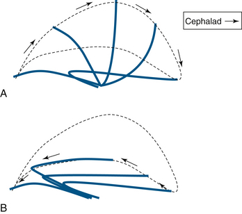
FIGURE 7-2 The cilial beat cycle. A, Demonstration of the effective stroke with the cilium erect; the cilial claws grab mucus and propel it cephalad. B, The recovery stroke, during which the cilium bends and returns to its rest position through the periciliary fluid layer.
Particulate matter transported to the upper airway may be cleared by coughing, which involves rapid inspiration followed by brief closure of the glottis. During this time, elastic recoil and active expiratory contraction increase intrathoracic pressure. When the glottis opens, explosive expiration at over 10 L/sec causes shearing and expectoration of secretions. Effective coughing requires an adequate peak expiratory flow rate and adequately hydrated mucus secretions.
Mucociliary Clearance
Mucociliary clearance may be reduced as a result of abnormal mucus production or cilial activity. In cystic fibrosis, the abnormal transmembrane conductance protein is a chloride ion channel. This results in reduced chloride and water content in the mucus, making it abnormally viscous and thereby reducing clearance and encouraging bacterial colonization.12 In other inflammatory airway diseases, hypertrophy of mucus glands may result in viscous secretions and a reduced periciliary watery layer that may inhibit the ciliary recovery stroke.
Reduced cilia activity may be congenital in conditions such as primary ciliary diskinesia, in which ciliary ultrastructure is abnormal.13 The time taken for effective ciliary clearance is approximately doubled in cigarette smokers.14 Pathogens such as Pseudomonas aeruginosa and Haemophilus influenzae reduce beat frequency.15 In addition, ventilated critically ill patients may have reduced mucociliary transport as a result of loss of cilia.16
Consequences of Underhumidification
In the presence of inadequate ambient humidity, prolonged excessive mucosal water loss results in viscous mucus that inhibits ciliary movement, especially the recovery stroke in the depleted deep, watery layer. Mucus flow is significantly reduced below a relative humidity of 50% at 37° C (absolute humidity 22 mg/L).17 Dry membranes have a reduced capacity to humidify inspired gas, and the ISB moves distally, exposing more distal airways to risk of injury. Ciliary loss, mucosal inflammation, epithelial ulceration, and necrosis may eventually occur. Hyperviscous secretion may obstruct bronchi or endotracheal tubes, and encrustation may occur and cause sputum retention, infection, atelectasis, reduced functional capacity, ventilation/perfusion (V/Q) mismatch, and reduced compliance.18,19 In addition, ventilation with dry gases may exacerbate hypothermia, especially in neonates and children.
Consequences of Overhumidification
When inspired gases are delivered at approaching or exceeding body temperature and fully saturated, the normal humidifying and heating actions of the upper airway cannot occur and may even be reversed. Condensation of water occurs in the airway with consequent reduced mucosal viscosity and risk of water intoxication. Inefficient mucociliary transport results, along with increased airway resistance, risk of pulmonary infection, surfactant dilution, atelectasis, and V/Q mismatch.2 Hot, humid gases may cause tracheitis by direct thermal injury to the epithelium.20
Filtration
Inhaled gases commonly carry a suspension of solid or liquid particles known as aerosols. Most aerosols are polydisperse, meaning they contain a range of particle sizes. Aerosol particles usually firmly attach to surfaces they are in contact with. Particles may make contact with surfaces by five different methods as gas flow is altered around an obstructing surface:
1. Inertial impaction occurs when a particle cannot follow a change in gas direction because of its inertia.
2. Interception occurs when a particle has low inertia but makes partial contact with a surface because of its large diameter.
3. Brownian motion occurs when small particles move in an apparently random pattern under the influence of surrounding gas molecules.
4. Gravitational settling typically occurs with large particles as they deviate from a gas stream under the influence of gravity.
5. Electrostatic deposition occurs when a particle deviates from the gas stream as a result of electrostatic attraction.
Large particles, those greater than 10 μm in diameter, typically deposit in the larynx or above. In the airways below this level, inertial impaction is the most significant mechanism for large particles in the larger airways, with gravitational settling becoming more important with lower velocities in smaller airways. Brownian motion is important throughout the airways for transportation of small particles.21
Artificial filters are generally formed of a mat of fine fibers of paper, glass, or plastic. Because gas flow changes repeatedly as gas flows around the fibers, the chances of contact with the filter increase. An electrostatically charged filter will also benefit from electrostatic deposition. Particles of different sizes make contact with surfaces to different degrees with each mechanism. Intermediate-size particles, those around 0.3 μm, are under the least influence by these five combined forces. In this context, 0.3 μm is regarded as the most penetrating particle size (MPPS) for most filters.22
The properties of filters vary enormously. Filtration efficiency describes the proportion of test particles prevented from passing beyond a filter. In this context, filtration efficiency is more commonly quoted in terms of bacterial filtration efficiency (BFE) or viral filtration efficiency (VFE). These terms describe the efficiency of the filter to stop particles of a nonpathogenic test bacterial or viral challenge aerosolized into droplets around 3.0 μm in diameter. Many bacteria have a similar diameter; viruses are smaller, although it must be noted this is a relatively large particle, 10 times the diameter of the MPPS. This large diameter results in a high apparent filtration fraction with this test. An efficiency of 99.97% indicates that 30 particles out of 100,000 aerosolized particles penetrate the filter in testing. Filters with an efficiency of 99.999% of the BFE or VFE are now available. The alternative “salt test” reveals the proportion of aerosolized 0.3-μm diameter sodium chloride particles prevented from penetrating the filter. Because this is the MPPS, this test usually results in a much lower apparent filtration efficiency. The efficiency claims of an individual HME must be understood in the context in which it was tested.21
Humidification Devices
As previously discussed, under normal physiologic conditions, much of the work of heating and humidification of inspired gas occurs in the nose. By the time the inspired gas reaches the mid trachea, its temperature is approximately 34° C, and it contains 34 to 38 mg/L water. As gas travels down into the lower airway, it is further heated to 37° C and 100% relative humidity (absolute humidity 44 mg/L). With intubation, the nasopharynx is bypassed. Humidification of dry medical gases now occurs in a more distal region, and the ISB moves distally.
Humidification devices—which may be passive, such as HMEs, or active, such as heated humidifiers—aim to reproduce more normal physiologic conditions in the lower respiratory tract. Achievement of absolute humidity levels of 30 to 35 mg/L in the trachea in clinical practice avoids significant heat and moisture loss and complications of mucosal drying.2 Overheating of inspired gases must also be avoided. If the gases are overheated, the saturated vapor pressure will increase. If that gas subsequently cools to the patient’s temperature as it enters the airway, the saturated vapor pressure will drop, causing water to condense and “rain out.”
Heat and Moisture Exchangers
HMEs consist of an outer casing with an inlet and an outlet with a partial barrier in between. They are placed close to the patient, on the distal end of the endotracheal tube or laryngeal mask airway (LMA). A closed suction unit or flexible extension may be placed between the HME and the airway, and some HMEs have integral flexible extensions, a piece angled 90 degrees, and a sampling port for sidestream capnography. It must be noted that measured end-tidal carbon dioxide on the machine side of the HME is significantly lower than that measured on the patient side, in both spontaneously and mechanically ventilated patients.23
HMEs are a compact, inexpensive, efficient, and non–energy-requiring solution to humidification of relatively cool and dry inspired gases. An HME is, in effect, an “artificial nose”—a passive device or barrier that retains the stored moisture and thermal energy of expired gases—within the lower respiratory tract.
HMEs may be either hygroscopic or hydrophobic. Hygroscopic HMEs use a paper or other fiber barrier coated with moisture-retaining chemicals that also may have some electrostatic properties. They may be made of a composite with an intermediate electrostatic membrane between hygroscopic layers. These adsorb water in expiration and release it in inspiration and usually are the most efficient devices for retaining heat and moisture. Being fiber based, they are more prone to becoming saturated, resulting in increased inspiratory/expiratory resistance and reduced heat and moisture retention efficiency.
Hydrophobic HMEs contain a pleated hydrophobic membrane that contains small pores, and they tend to be more efficient filters of pathogens.24 When using an HME, humidity reaches steady state in the lower respiratory tract within a few breaths. The International Standards Organization (ISO) 9360 standard specifies the lung model, ventilator settings, and absolute humidity standards for HMEs for a standardized 24-hour test.25
Potential Hazards and Limitations of Heat and Moisture Exchangers
A range of HMEs is available, with wide variations in properties (Fig. 7-3). A number of factors must be taken into account in selecting an appropriate HME. The internal volume of these devices can vary from approximately 12 to 100 mL, and resistance can be in the range of 0.7 to 3.8 cm H2O/L/sec.26 HMEs introduce inspiratory, expiratory, and dead space resistance to the anesthesia circuit. The HME design should aim to reduce this resistance to prevent increased work of breathing and hypercapnea, especially in pediatric patients or when ventilating adults with a low tidal volume strategy. This effect may be overcome in mechanically ventilated patients but may require the addition of up to 5 to 10 cm H2O inspiratory pressure.27
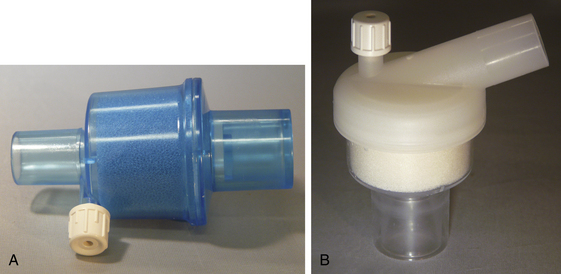
FIGURE 7-3 Portex (A) (Smiths Medical, St. Paul, MN) and Hudson RCI (B) (Durham, NC) heat and moisture exchangers. Both have a foam element and a port for gas sampling.
HMEs may become progressively or acutely obstructed, especially by deposition of proteinaceous fluid such as sputum or blood. Acute obstruction is a rare but life-threatening event, so regular visual inspection of the HME is recommended. It is also recommended that the HME be replaced after every 24 hours of use. However, studies of the prolonged use of single filters found they still keep their moisture-retaining efficiency at 7 days without significant increase in resistance.28
Tests of HMEs in vivo show that their performance may vary significantly from that quoted for testing in vitro.29 Efficiency may reduce with large tidal volumes, especially with membrane-based hydrophobic models. The need for a high-efficiency HME may be lessened when using low flows in circle systems. Some of this will be due to rebreathing of expired humidified gas plus the added effect of the heat- and water-generating reaction of CO2 with soda lime. In pigs ventilated on a circle without an HME, a humidity level of 27 mg/L was noted in the inspiratory limb with an inspiratory flow of 0.6 L/min.30 The efficiency of this approach seldom matches that of an HME. When using a pediatric circle, a low fresh gas flow (0.5 L/min) is associated with greater relative humidity than a high flow (6 L/min). However, the same low and high flows with an HME are associated with significantly better moisture retention at 20 minutes, and heat retention at 70 minutes, than even low flows without an HME.31 Without an HME, the lag may be significant, up to an hour, to achieve adequate moisture and humidity even with flows of 1.5 L/min.32 HMEs have unpredictable performance when used in conjunction with active humidification systems, and their combination generally is not recommended because it may result in saturation of the HME or removal of the hygroscopic coating.
Selecting an appropriate HME in pediatric practice is particularly difficult. Infants and neonates are especially vulnerable to respiratory water and heat loss as a result of a large ratio of minute volume to surface area. This may compound other potential heat losses, such as from a large ratio of skin surface area to volume, and may result in nonshivering thermogenesis in neonates. HMEs with low dead space are preferred, but these often have a lower moisture-retention efficiency. However the applicability to most pediatric practice of quoted in vitro performance at the relatively high test flows of 15 L/min has been brought into question. No HMEs are currently licensed for neonates who weigh less than 3 kg; treatment of such neonates requires the use of active humidifiers.
Heat and Moisture Exchanger Filters
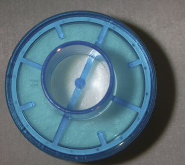
HMEs may be modified to prevent bidirectional passage of both airborne and waterborne pathogens. These modified devices are known as heat and moisture exchanger filters (HMEFs), and they are the most commonly used device. HMEFs are designed to remove liquid or solid particles (aerosols) suspended in gas. This is achieved by reducing the pore size of the HME to less than 0.2 μm and/or coating it with a bacteriostatic or electrostatic substance. Larger particles may collide with the filter by direct inertial impaction or interception because the particle cannot follow the path of gas through the obstruction, or they may settle under gravitational influence. Small particles deviate from the gas flow by Brownian motion and make contact with fibers in the filter, and charged particles may be attracted to electrostatic filter fibers. Once in contact with the filter, particles generally adhere firmly (Figs. 7-4 and 7-5).
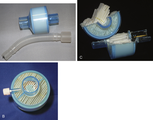
FIGURE 7-4 A, A Portex (Smiths Medical, St. Paul, MN) heat and moisture exchanger with a high-efficiency particulate air filter and gas sampling port and optional flex tubing. The medium is a hydrophobic membrane. B and C, Cutaway of the device to demonstrate the folded design of the membrane, which greatly increases its surface area.
Potential Hazards and Limitations of Heat and Moisture Exchanger Filters
The HMEF helps the expiratory limb of the breathing circuit stay relatively dry, cool, and free of bacteria. It avoids condensation of water as cooling gas reaches its dew point, at which it may form a reservoir for nosocomial infection. In practice HMEFs are used to protect the patient from the inhaled particles and the anesthesia circuit from the patient to allow reuse. Modern anesthesia circuits are designed as single-use items, but for practical and economic reasons, some anesthesia circuits licensed for single use may be reused for up to 7 days in accordance with manufacturer guidelines, with a change of HMEF with each patient. Certain products have a special indemnity to be used for 7 days, with a new HMEF for each patient, but these should be changed if they become visibly soiled or after use on a known infectious patient.33
No available filter is 100% efficient for all possible particle sizes. Evidence suggests that even bactericidal filters cannot reliably prevent contamination of the machine side of the circuit.34 The clinical significance of circuit contamination and possible progression to clinical infection in subsequent patients in conjunction with a new HME is hotly debated. Current guidance by Association of Anaesthetists of Great Britain and Ireland is that the breathing circuit can be reused if a new suitable filter is used. Where use of a filter is undesirable, the circuit should be changed after each patient.31 Guidelines for pediatric practice recommend that the circuit should be changed between each patient,31 although in practice, circuits are often reused in conjunction with an HMEF. In the United States and Canada, practice is to replace the anesthesia circuit after each patient.35
Heated Humidifiers
Active heating and humidification of inspiratory gases may be considered when the mechanical effects of an HME or HMEF are undesirable, such as in neonates; patients with difficult respiratory secretions; or those in whom it is desirable to absolutely minimize heat or respiratory water losses, as with hypothermia.
Heated humidifiers contain a humidification chamber composed of water and a heat source. Gas may be passed over, or bubbled through, the reservoir. A heated wire inside the inspiratory limb may prevent gas cooling below its dew point and causing condensation; if this is not included, a water trap is required. Most heated humidifiers have a sensor at the patient end of the circuit with a servo control that regulates the output of the heating element. If excessive temperature is detected, the heat source power usually is cut as a safety feature. Inspiratory gas typically is heated to between 34° C and 40° C (Fig. 7-6).
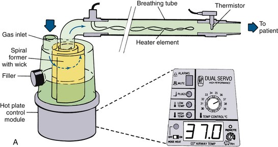
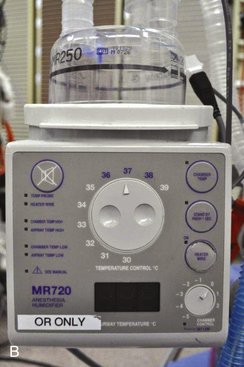
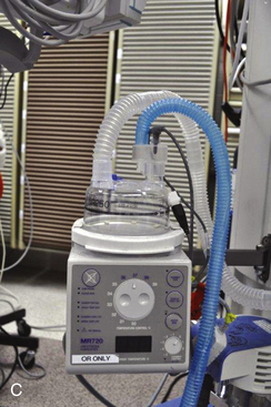
FIGURE 7-6 A, Fisher & Paykel Healthcare (Auckland, New Zealand) humidifier system with heater element in the breathing tube. The unit shown has a spiral aluminum scroll and paper wick to increase evaporation during high flows. Also shown are the alarms and relative humidity control. The heated wire keeps the temperature of the gas constant and prevents “rain out.” B, Fisher & Paykel dual servo heated humidifier, model MR720, for use in the operating room. The temperature and relative humidity can be adjusted. C, Humidifier in a breathing circuit. Note the heater wire inside the blue tubing. (A, From Mushin W, Jones P: Physics for the anaesthetist, ed 4. Boston, 1987, Blackwell Scientific. B anb C, CourtesyK. Premmer, MD.)
Potential Hazards and Limitations of Heated Humidifiers
Heated humidifiers require energy and increased workload for filling, draining, and maintenance; hence, they are more expensive to run than HMEs. Heated humidifiers have a theoretical risk of electrical malfunction or overheating and thermal injury that is not possible with HMEs, and they carry risk of water aspiration from the tubing, water trap, or reservoir. In addition, heated humidifiers are not always more efficient than an HME. An efficient HME may reduce water losses to less than 7 mg/L, which is less than normal lower airway physiologic loss. The ISO minimum standard for the performance of an active humidifier is 33 mg H2O/L, which would result in a water loss to the patient of 11 mg/L, falling below the efficiency of many HMEs. Heating inspired gas to 34° C does not improve humidification above that of an efficient HME. Only at temperatures of 37° C to 40° C can a heated humidifier reduce respiratory losses below 7 mg/L.
As saturated warm gas cools in the expiratory limb, it may reach its dew point and condense, which may rapidly form a reservoir that may become colonized with bacteria.36 This is clearly a dangerous source of cross infection that precludes reuse of the circuit with another patient. Whether this reservoir of the patient’s own flora can predispose to ventilator-associated pneumonia (VAP) is still under debate. Many individual studies have found no increase in the incidence of VAP with heated humidification, but a meta-analysis of eight randomized controlled trials (RCTs) found a relative risk reduction for VAP of 0.7 with HME use versus a heated humidifier,37 particularly on patients ventilated for more than 7 days. However, a more recent RCT found an increase in VAP with HMEs and HMEFs over heated humidifiers.38 With conflicting evidence, it is difficult to establish whether either is more associated with VAP, and this is reflected in a lack of official guidance on the matter.
Summary
Understanding the importance of providing adequate heat and moisture to inspired medical gases to avoid patient harm is increasing. Optimal warmth and humidification can be achieved actively with heated humidifiers or passively with an HME or HMEF. Increasingly, HMEs and HMEFs are becoming the standard for routine humidification in anesthesia, and individual models vary enormously in their efficiency and in their effects on dead space and resistance. Heated humidifiers are expensive, cumbersome, labor intensive, and capable of achieving only a small benefit over HMEs and HMEFs in routine anesthesia. Heated humidifiers do offer some advantages in situations, such as with neonatal anesthesia and low tidal volume ventilation, in which the mechanical effects of HMEs and HMEFs may become significant. Further investigation may be required to determine whether heated humidifiers increase the incidence of VAP.
HMEFs are increasingly used to protect patients from inhaled microorganisms and allow circuit reuse. Although HMEFs have increasingly high filtration efficiencies, and infection with circuit reuse in this way has not been proven, no HMEF provides a complete microbiologic barrier.
References
1. Shelly M.P. Conditioning of inspired gases. In: Marini J.J., Slutsky A.S., eds. The physiological basis of ventilatory support. New York: Marcel Dekker; 1998:575–593.
2. Sottiaux T.M. Consequences of under- and over-humidification. Respir Care Clin North Am. 2006;12:233–252.
3. Guyton A.C. Partition of the body fluids: osmotic equilibria between extracellular and intracellelular fluids. In: Guyton A.C., ed. Textbook of medical physiology. Philadelphia: WB Saunders, 1986.
4. Dery R., Pelletier J., Jacques A. Humidity in anaesthesiology III. Heat and moisture patterns in the respiratory tract during anaesthesia with the semi-closed system. Can Anaesth Soc J. 1967;14:287–294.
5. Dery R. Humidity in anaesthesiology. Part IV: Determination of the alveolar humidity and temperature in the dog. Can Anaesth Soc J. 1971;18:145–151.
6. Walker J.E.C., Wells R.E., Merrill E.W. Heat and water exchange in the respiratory tract. Am J Med. 1961;30:259–267.
7. Sleigh M.A., Blake J.R., Liron N. The propulsion of mucus by cilia. Am Rev Resp Dis. 1988;137:726–741.
8. Negus V.E. Humidification of the air passages. Thorax. 1952;7:148–151.
9. Widdicombe J.H. Regulation of the depth and composition of airway surface liquid. J Anatomy. 2002;201:313–318.
10. Conway J.H., Holgate S.T. Humidification for patients with chronic chest disease. Probl Respir Care. 1991;4:463–473.
11. Eckerbom B. The airways during artificial respiration, Acta Universitatis Upsaliensis, comprehensive summaries of Uppsala dissertations from the faculty of medicine. Stockholm: Aimqvist & Wiksell International; 1990;vol 5. 253
12. Jiang C., Finkbeiner W.E., Widdicombe J.H., Miller S.S. Fluid transport across cultures of human tracheal glands is altered in cystic fibrosis. J Physiol. 1997;501:637–648.
13. Rossman C.M., Lee R.M.K.W., Forrest J.B., Newhouse M.T. Nasal ciliary ultrastructure and function in patients with primary ciliary dyskinesia compared with that in normal subjects and in subjects with various respiratory diseases. Am Rev Respir Dis. 1984;129:161–167.
14. Stanley P.J., Wilson R., Greenstone M.A., et al. Effect of cigarette smoking on nasal mucociliary clearance and ciliary beat frequency. Thorax. 1986;41:519–523.
15. Wilson R., Roberts D., Cole P. Effects of bacterial products on human ciliary function in vitro. Thorax. 1985;40:125–131.
16. Konrad F., Schreiber T., Brecht-Kraus D., Georgieff M. Mucociliary transport in ICU patients. Chest. 1994;105:237–241.
17. Forbes A.R. Humidification and mucus flow in the intubated trachea. Br J Anaesth. 1973;45:874–878.
18. Noguchi H., Takumi Y., Aochi O. A study of humidification in tracheotomized dogs. Br J Anaesth. 1973;45:844–847.
19. Rashad K., Wilson K., Hurt H.H., et al. Effect of humidification of anaesthetic gases on static compliance. Anesth Analg Curr Res. 1967;46:127–133.
20. Sims N.M., Geoffrion C.A., Welch P.J., et al. Respiratory tract burns caused by heated humidification of anesthetic gases in intubated, mechanically ventilated dogs: a light microscopic study. Anaesthesiology. 1986;65:A490.
21. Thiessen R.J. Filtration of respired gases: theoretical aspects, Respir Care Clin North Am. 2006;12:183–201.
22. Demers R.R. Bacterial/viral filtration: let the breather beware!. Chest. 2001;120:1377–1389.
23. Hardman J.G., Curran J., Mahajan R.P. End-tidal carbon dioxide measurement and breathing system filters. Anaesthesia. 1997;52:646–648.
24. Dorsch J.A., Dorsch S.E. Humidification equipment. In Dorsch J.A., Dorsch S.E., eds.: Understanding anaesthesia equipment, ed 5, Philadelphia: Lippincott, Williams & Wilkins, 2008.
25. International Organization for Standardization (ISO). Anaesthetic and respiratory equipment—heat and moisture exchangers (HMEs) for humidifying respired gases in humans—Part 1: HMEs for use with minimum tidal volumes of 250 mL, ISO 9360-1. Geneva: International Organization for Standardization, Geneva Technical Committee; 2000.
26. Iotti G.A., Olivei M.C., Braschi A. Equipment review: mechanical effects of heat-moisture exchangers in ventilated patients. Crit Care. 1999;3:R77–R82.
27. Pellosi P., Solca M., Ravagnan M., et al. Effects of heat and moisture exchangers on minute ventilation, ventilatory drive, and work of breathing during pressure-support ventilation in acute respiratory failure. Crit Care Med. 1996;24:1184–1188.
28. Ricard J.D., Le Miere E., Markowicz P., et al. Efficiency and safety of mechanical ventilation with a heat and moisture exchanger changed only once a week. Am J Respir Crit Care Med. 2000;161(1):104–109.
29. Lemmens M.J.M., Brock-Utne J.G. Heat and moisture exchange devices: are they doing what they are supposed to do? Anesth Analg. 2004;98:382–385.
30. Kleemann P.P. The climatisation of anaesthetic gases under conditions of high flow to low flow. Acta Anaesthesiol Belg. 1990;41:189–200.
31. Nakae Y., Horikawa D., Tamiya K., et al. Humidification during low flow anaesthesia in children. J Anaesth. 1998;12:175–179.
32. Kleeman P.P. Humidity of anaesthetic gases with respect to low flow anaesthesia. Anaesth Intensive Care. 1994;22:396–408.
33. Association of Anaesthetists of Great Britain and Ireland. Infection control in anaesthesia. Anaesthesia. 2008;63:1027–1036.
34. Neft M.W., Goodman J.R., Hlavnika J.P., Velt B.C. To reuse your circuit: the HME debate. AANA J. 1999;67:433–439.
35. Carter J.A. The reuse of breathing systems in anaesthesia. Respir Care Clin. 2006;12:275–286.
36. Craven D.E., Goularte T.A., Make B.J. Contaminated condensate in mechanical ventilator circuits: a risk factor for nosocomial pneumonia. Am Rev Respir Dis. 1984;129:625–628.
37. Kola A., Eckmanns T., Gastmeier P. Efficacy of heat and moisture exchangers in preventing ventilator-associated pneumonia: meta-analysis of randomised controlled trials. Intensive Care Med. 2005;31:5–11.
38. Lorente L., Lecuona M., Jimenez A., et al. Ventilator-associated pneumonia using a heated humidifier or a heat and moisture exchanger: a randomized controlled trial. Crit Care. 2006;10:R116.