Airway Equipment
ORAL AND NASOPHARYNGEAL AIRWAYS
Overview
Of all the equipment in the toolbox of the anesthesiologist, airway devices may be the most commonly used as well as the most varied in design and function. The last decade has witnessed a remarkable expansion of the airway armamentarium, necessitating a review of traditional and modern devices. The anesthesia face mask and tracheal tube once comprised the bulk of airway management apparatus; supraglottic airways, video laryngoscopes, and minimally invasive devices have now captured a significant share of both routine and rescue tools. In an attempt to be clinically relevant, this chapter focuses little on historic devices and the forces guiding instrument evolution; that is, the causes, pressure, and findings that led to device development. The exception to this is a historic discussion of the origins of airway management, including tracheal intubation. Although we recognize the importance of historic perspective of all the devices in use today, more authoritative reviews exist.
Anesthesia Face Mask
The anesthesia face mask was invented in 1917. Prior to that, inhalational anesthesia was administered by an open-drop ether technique. The face mask allowed the administration of gases to the patient without instrumentation of the airway. The face mask may be considered the original supraglottic device; it comes in both adult and pediatric sizes. The face mask is held over the patient’s face to encompass the patient’s nose and mouth. Two fingers are placed over the body of the mask to firmly hold it in place, and three fingers are placed along the bony mandible to complete a tight seal. In edentulous patients, it may be necessary to include the chin of the patient in the mask to compensate for the lack of dentition.
Anesthesia masks are made either of silicone or rubber. In the past, anesthesia masks were opaque, but most modern anesthesia masks are clear to allow the provider to view the patient’s lip color, condensation from expiration, secretions, vomitus, and any expelled blood. In some practices, the rubber mask is reusable.
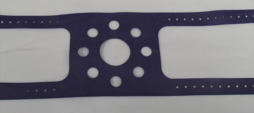
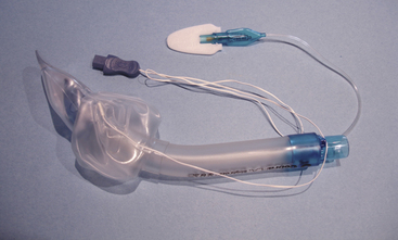
When positioning the mask, the clinician must be careful not to compress the facial nerve and artery, the eyes, or the lips. Face mask fit can be engaged with the help of a head strap (Fig. 16-1) attached to a four-prong ring that encircles the circuit fitting. The head strap is helpful for the clinician with small hands, when the patient is edentulous or has a large face or beard, or to allow providers to have their hands free when the patient is breathing spontaneously.
Oral and Nasopharyngeal Airways
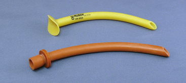
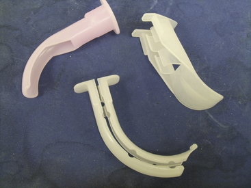
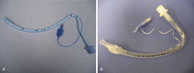
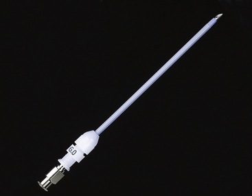
An oral airway prevents the base of tongue and the epiglottis from obstructing the pathway to the larynx. With a few exceptions, oral airways are made from a hard plastic and are inserted into the mouth with their concave surface facing cephalad. Once well within the oral cavity, the airway is rotated 180 degrees so that the preformed concavity comes to its final position following the contour of the tongue. The proximal end of the airway has a flange to prevent the entire device from falling into the mouth; the distal tip sits just above the epiglottis. Because of the position against the base of tongue and posterior pharyngeal wall, oral airways are poorly tolerated in the awake or inadequately anesthetized patient. Nasal airways are made from soft, flexible materials and are tolerated better in awake patients than are oropharyngeal airways (Fig. 16-2). Appropriate nasal airway sizing is determined by measuring the distance from the patient’s bony mandible or nostril to the meatus of the ear. Some of the commonly available oral airways include the Berman-Guedel, the split Berman, and the Ovassapian and Williams airways used in fiberoptic laryngoscopy (Fig. 16-3).
Supraglottic Airways
Obstruction of the airway was a poorly understood phenomenon prior to 1874. Opening the mouth with a wooden screw and drawing out the tongue with a forceps or steel-gloved fingers was the height of airway management.1 Recognition that the base of the tongue falling against the posterior pharyngeal wall accounted for most airway obstruction did not occur until 1880.2 Credit for the first use of a true supraglottic airway is given to Joseph Thomas Clover (1825–1882), although it is possible that similar devices were used toward the end of the second millennium.3 Clover used a nasopharyngeal tube for the delivery of chloroform anesthesia. The O’Dwyer tube was introduced in 1884, a device that consisted of a curved metal tube with a conical end that could seal the laryngeal inlet when placed into the oropharynx.3 Although designed for the treatment of narcotic overdose, it was later modified to be used with volatile anesthetics. Over the next 50 years, several modifications of the basic oropharyngeal airway were described. In the 1930s, Ralph Waters introduced the now familiar flattened-tube oral airway.4 Guedel modified Waters’ concept by fitting his airway within a stiff rubber envelope in an attempt to reduce mucosal trauma.5
Tracheal intubation was first described in 1788 as a means of resuscitation of the “apparently dead”6 but was not used for the delivery of anesthesia until almost 100 years later.7 The forerunner of the modern tracheal tube was designed by the German otolaryngologist, Dr. Franz Kuhn (1866–1929), who developed a flexible metallic tube that resisted kinking and could be shaped to the patient’s upper airway anatomy.8 The tube was inserted using a rigid stylet, and the hypopharynx was sealed with oiled gauze packing. Sir Ivan Magill and Stanley Rowbotham are credited with the initial development of modern tracheal intubation. Performing anesthesia for reconstructive facial surgery during World War I, they developed a two-tube nasal system. One narrow tube of a gum elastic design was passed through the nares and guided into the larynx using a surgical laryngoscope. The other tube was blindly passed into the pharynx to provide for the escape of gases. During use of this “Magill” tube, the exhaust lumen would occasionally pass into the larynx, leading Sir Ivan to describe blind nasal intubation.9
Cuffed supralaryngeal airways were initially described in the early part of the twentieth century. The impetus for the development of these devices was threefold. First, the introduction of cyclopropane, an explosive agent, required an airtight circuit for appropriate evacuation. Second, blind and laryngoscope-guided tracheal intubation remained a difficult task. Third, protection of the lower airway from blood and surgical debris in the upper airway was an important concern.10 The Primrose cuffed oropharyngeal tube, the Shipway airway—which was a Guedel oropharygeal airway fitted with a cuff and circuit connector designed by Sir Ivan Magill—and the Lessinger airway were predecessors of the modern supralaryngeal devices. In 1937 Leech introduced a “pharyngeal bulb gasway” with a noninflatable cuff that fit snugly into the hypopharynx.11 The use of supralaryngeal airways remained dominant until the introduction of curare in 1942 and the mass training of anesthetists in tracheal intubation in anticipation of and during World War II.12 Mendelson’s description of gastric contents aspiration in obstetric cases (66 of 44,016 patients, with 2 deaths) further pushed the move toward tracheal intubation in most surgical procedures.13 Within a few years, proficiency in direct laryngoscopy and tracheal intubation became a mark of professionalism.14 The advent of succinylcholine in 1951 furthered the dominance of tracheal intubation by providing rapid and profound muscle relaxation.
By 1981, two types of airway management prevailed: tracheal intubation and the anesthesia face mask/Guedel airway. Although both were time-tested devices, each had its failings (apart from airway failure in a small number of patients). Tracheal intubation was associated with both dental and soft tissue injury and cardiovascular stimulation, and mask ventilation often required a hands-on-the-airway technique. These difficulties led to the reconsideration of supralaryngeal airways.
Laryngeal Mask Airway
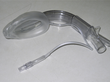
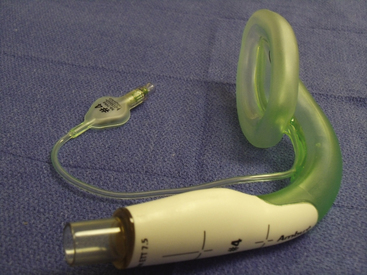
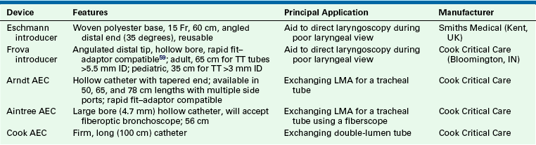
The laryngeal mask airway (LMA) was developed by Dr. Archie Brain in 1982. An exhaustive review of the history of the LMA and its inventor can be found in the text by Joseph Brimacombe.15 The “classic” LMA (LMA Classic; LMA North America, San Diego, CA) became commercially available in 1988 in England (1992 in the United States). At the time of this writing, the LMA had been used in an estimated 200 million patients. Its components are 100% silicone rubber (no latex), except for a metal spring and a polypropylene component in the inflation valve. It is a reusable device that has a lifespan of 40 uses or cleanings. The mask consists of three components: an inflatable cuff, an airway barrel, and an inflation line (Fig. 16-4). The airway tube is semirigid and semitransparent. Proximally, a standard 15-mm circuit adaptor is permanently fused to the barrel; distally, the barrel is fused to the inflatable cuff. Two flexible aperture bars cross the junction between the barrel and the mask and prevent obstruction by the epiglottis. The aperture bars are flexible enough to allow instrumentation (e.g., intubation) without their removal. The mask is oblong and based on plaster casts of cadavers. The distal aspect is narrow (over the esophageal inlet), whereas the proximal cuff is broad (upper hypopharynx). With the pilot cuff and syringe tip–activated air valve, the inflation line emerges from the most proximal aspect of the cuff, just behind the barrel-cuff junction.16 The LMA Classic comes in sizes 1 through 6, with smaller half sizes (1.5 and 2.5); cuff length changes approximately 15% between sizes. The LMA Classic was released in 1998 in a single-use version made of polyvinyl chloride (PVC). Although the LMA Unique has identical dimensions to the LMA Classic, the barrel is more rigid. A rerelease of this device, the LMA Unique in 2000, had a softer barrel and cuff backplate. The LMA has been used in a wide variety of surgical and resuscitative procedures, including spontaneous and controlled ventilation cases,17 laparoscopy,18 otolaryngology, and cardiothoracic surgery, in all body positions, in morbidly obese patients, and in other applications.16 The most feared complication of supraglottic airway (SGA) use, an increased rate of aspiration of gastric contents, has not been realized when the LMA has been used correctly in appropriate patients.19
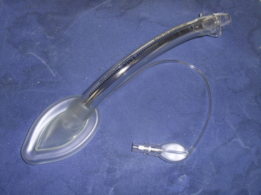
FIGURE 16-4 Single-use version of the classic Laryngeal Mask Airway, the LMA Unique (LMA North America, San Diego, CA).
Other versions of the LMA, which were never commercially available, include the nasal LMA, with the barrel and mask assembled in the pharynx; the double-lumen LMA, in which the second lumen is used for instrumentation; the malleable LMA, with a malleable external stylet that allows shaping; the split LMA, to facilitate fiberoptic-aided tracheal intubation; the short-tube LMA, to facilitate through-LMA tracheal intubation; the wide-barrel LMA, to accept a 9-mm tracheal tube; and the gastroscope LMA, to allow passage of an endoscope. Descriptions and citations for these devices can be found in exhaustive reviews by Brimacombe.15
A number of accessory devices have been developed by Brain, independent clinicians, and researchers. Two devices have been introduced by Brain to facilitate deflation of the LMA cuff—the block deflation tool and the spring-loaded shoehorn deflation tool.20 A wide range of insertion aids include an artificial palate, intralumenal devices, extralumenal devices, and laryngoscope-like blades.21 Commonly available airway devices have been used to facilitate both tracheal intubation via the classic LMA and its removal after intubation, including the gum elastic bougie, fiberscopes, gastric tubes, and guidewires.22 Likewise, many different devices have been used to verify the position of the in situ LMA, including light wands, fiberscopes, and the Patil intubation guide (Anesthesia Associates, San Marcos, CA).22
Although the LMA shows some resistance to low-power laser strikes, these devices are generally considered non–laser compatible. Details on resistance to a variety of laser sources are available.23 The metallic spring in the pilot cuff of the LMA Classic and some other LMAs is not MRI compatible; however, no morbidities have been associated with its use, although there have been reports of the spring interfering with the quality of the magnetic resonance image (MRI).24 An MRI-compatible LMA is available that uses a plastic spring. The metal reinforcement in the LMA Flexible and LMA ProSeal is non–MRI compatible, as is the barrel of the reusable Fastrach and Ctrach LMAs. The silicone cuff of the LMA is permeable to nitrous oxide (N2O), and intracuff pressure will increase during N2O anesthesia.25,26 The LMA contains no natural latex.
Cleaning and sterilization are important steps in the use of any reusable device, and appropriate cleaning improves the safety and longevity of LMA products. Manual cleaning is done with sodium bicarbonate, soapy water, or a mild enzymatic cleaner. Other chemical agents should be avoided, and a soft brush should be used to remove secretions. During cleaning, every attempt should be made to keep the inflation valve dry because water may cause malfunction. After cleaning, the device should be reinspected for soiling or damage. Sterilization is by steam autoclave, and the cuff of all LMAs should be emptied of air immediately before autoclaving (spontaneous reinflation will occur if the device is left for hours prior to sterilization). Immediate spontaneous reinflation may indicate a faulty inflation valve; if this happens, the device should be discarded. Small amounts of gas in the cuff may cause rupture during autoclaving, and autoclave temperature should not exceed 135° C. The duration of the autoclave cycle can be from 3 to 15 minutes depending on the autoclave mechanism. The manufacturer suggests that all reusable LMAs be discarded after 40 uses.
Although a number of LMA modifications have been made, only a handful have found widespread acceptance and commercial success. The following devices are based on the classic LMA but incorporate changes in the barrel or mask design that facilitate usability or improve safety.
The flexible LMA (FLMA; LMA Flexible, LMA North America) was designed to be used in surgical cases where the area in and around the airway must be shared with the surgical team. The barrel of the FLMA is longer and narrower than the classic LMA and is wire reinforced. It may be deflected away from the surgical field without kinking or placing torque on the cuff. When the surgical field includes the head or neck and heavy drapes cover the airway, the drapes can fall on the FLMA barrel with impunity. The FLMA is available in sizes 2 to 6, including a size 2.5. Neither the LMA Classic nor the FLMA is laser resistant, nor are they MRI compatible because of the reinforced barrel. The FLMA has been used for a wide variety of otolaryngeal surgeries, including adenotonsillectomy, uvulopalatoplasty, and dental, intranasal, ear, and eye procedures.27-29 The narrow barrel of the FLMA is not compressed by a surgical mouth gag, but placement requires cooperation between the anesthesiologist and surgeon. The barrel is placed midline under the grooved blade of the Dingman (or similar) mouth gag. Outward tension is applied on the FLMA barrel as the mouth gag is placed; this maneuver prevents redundancy of the barrel in the pharynx, which occurs as the blade shortens the distance over the tongue. During the mouth gag placement, care must be taken to ensure the FLMA inflation line is not trapped and occluded. The blade of the mouth gag must be appropriately sized; too large a blade can crush the proximal FLMA cuff, and too small a blade can pull the cuff out of position.
The principal concern among clinicians contemplating otolaryngeal procedures with the laryngeal mask has been airway protection from surgical blood and debris. Studies have shown superior airway protection compared with the use of a tracheal tube (or nasal mask in dental surgery) by virtue of the supraglottic seal.30
The cleaning procedure and life expectancy of the FLMA are identical to those of the LMA Classic. A single-use FLMA is also available.
ProSeal LMA
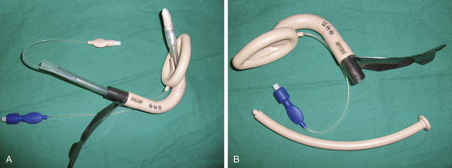
The ProSeal LMA (PLMA) was introduced in 2001 as an improved version of the LMA Classic. The PLMA is a relatively complex device compared with other laryngeal masks (Fig. 16-5, A and B). Differences in the ProSeal, compared with the LMA Classic, are listed in Table 16-1.
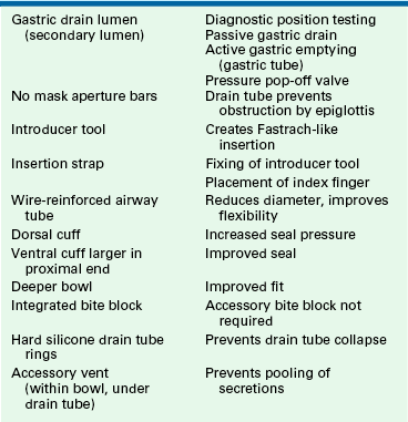
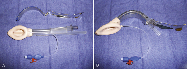
FIGURE 16-5 A, ProSeal Larygneal Mask Airway (LMA North America, San Diego, CA). B, With insertion handle attached.
There are three primary improvements of the PLMA: 1) diagnosis of device position, 2) access to the alimentary track, and 3) higher airway pressures. Although the incidence of complications during LMA anesthesia is similar to that of the tracheal tube, it is believed that poor positioning contributes to most of these events.19 In one well-described case report, aspiration of gastric contents occurred because of PLMA misplacement. Importantly, the clinician did not perform any confirmatory test to ensure the device’s correct position.31 Several techniques have been described to determine whether the PLMA is correctly inserted (Table 16-2).
TABLE 16-2
Tests to Ensure Proper Positioning of ProSeal Laryngeal Mask Airway∗
| Test | Observation | Reference |
| Bite block test | Depth of bite block adequate | 32 |
| Suprasternal notch test | Pressing on suprasternal notch moves bubble placed on gastric drain | 33 |
| Leak test | No gas leak from drain tube | 34 |
| Gastric tube placement | Tube placed into stomach ensures patency | 35 |
Because of the upper esophageal positioning of the PLMA’s nonairway lumen, access to the alimentary tract is possible. Gastric emptying may occur that may be passive, via regurgitation, or active, via Salem sump placement. Table 16-3 lists the maximum gastric tube diameter for each PLMA size. Brain suggests that the gastric tube not be left in situ during the maintenance phase of the anesthetic because the lumen of the gastric drain should be left unobstructed (see Table 16-3).
TABLE 16-3
Maximum Gastric Tube Diameters for ProSeal Laryngeal Mask Airways∗
| Airway Size | OG Tube Size |
| 1½ | 10 Fr |
| 2 | 10 Fr |
| 2½ | 14 Fr |
| 3 | 16 Fr |
| 4 | 16 Fr |
| 5 | 18 Fr |
Although the LMA Classic typically achieves a seal pressure of 20 to 25 cm H2O, some patients, such as the morbidly obese, may require positive airway pressure beyond this.36 Because of its deep bowl, and possibly the back cuff, the PLMA seals the airway to 40 to 45 cm H2O or more.37
LMA Supreme
The LMA Supreme may first be considered a disposable ProSeal LMA because of a similarly configured drain tube. The LMA Supreme also has a fixed-curve airway tube, like the Fastrach LMA. The LMA Supreme consists of a preformed airway tube, integrated bite block, gastric drain for placement confirmation and gastric decompression, and fixation tabs that help maintain the correct insertion depth. The LMA Supreme is available in adult sizes 3 to 5 (Fig. 16-6).
Fastrach LMA
The Fastrach (LMA North America), or intubating LMA (ILMA), was introduced in 1995 to improve the technique of tracheal intubation through the LMA. Several intubation techniques have been described through the LMA Classic, including blind, retrograde wire-assisted, flexible fiberoptic, light wand, bougie, and tracheal tube exchange catheter placements. Table 16-4 examines the problems with tracheal intubation via the LMA Classic and how the ILMA corrects these problems.
TABLE 16-4
Problems with Tracheal Intubation
| LMA Classic | Intubating LMA |
| 22 cm in length, requires long tracheal tube | 14 cm in length |
| Diameter accepts up to size 7.0 tracheal tube | Size 8.0 ID tracheal tube |
| Obstruction by epiglottis | Lifting bar raises epiglottis away from tracheal tube path |
| Difficult removal of LMA while leaving the tracheal tube in situ | Removal facilitated by large diameter and short length |
| Flexible barrel hinders readjustment | Stainless steel barrel |
| Fingers must be placed in the mouth during placement | Stainless steel handle facilitates insertion |
The stainless steel, silicone-coated barrel of the ILMA is anatomically shaped to fit the oral cavity–pharynx-hypopharynx axis, when the head is in the neutral position. This curve was based on the analysis of 60 sagittal MRI sections of patients with normal airways. The barrels of the three available sizes—3, 4, and 5—are identical. The masks vary in the size of the cuff and the placement of the epiglottic lifting bar (ELB). The ELB is a vertically oriented semirigid bar fixed at the proximal end of the bowl aperture and positioned to sit beneath the epiglottis in situ. As a tracheal tube is passed through the barrel, the EBL lifts the epiglottis out of its path to the larynx. A handle at the proximal end of the barrel is used for insertion, repositioning, and removal. A secondary advantage of the handle is that the operator does not need to place fingers into the patient’s mouth (Fig. 16-7).
The Fastrach is designed to be used with a straight, armored, silicone tracheal tube (Euromedics, Malaysia), although standard or Parker Flex-tip (Parker Medical, Englewood, CO) PVC tracheal tubes have been used.38 The Fastrach is indicated for routine, elective intubation and for anticipated and unanticipated difficult intubation. Because it was designed to facilitate blind tracheal intubation, the presence of airway secretions, blood, or edema, such as from previous intubation attempts or trauma, has not hindered its usefulness as a ventilating and intubating device after failed rapid-sequence intubation.38
Paraesophageal Devices
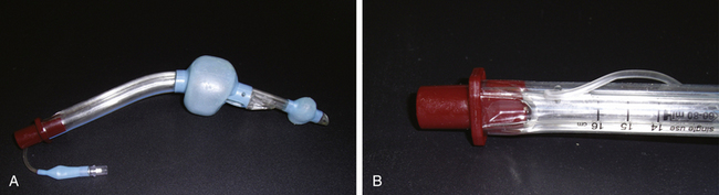
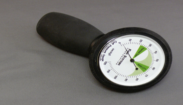
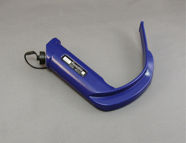
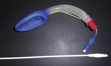
The King laryngeal tube (LT; King Systems, Noblesville, IN), is a latex-free, single-use, single-lumen silicone tube that consists of a 130-degree angled airway tube, an average barrel diameter of 1.5 cm, esophageal and oropharyngeal low-pressure cuffs, and two ventilation ports. The distal esophageal tube seals the esophagus and protects against regurgitation, while the proximal oropharyngeal tube sits in the oropharynx and seals both the oral and nasal cavities. During ventilation through the two ventilation ports, the trachea is oxygenated. The King LT is available in sizes 3 to 5 in the United States and in sizes 0 to 2 outside the United States. A double-lumen version of the King LT suction (LTS) also is available. One lumen is available for ventilation, and the other lumen is used for decompression of the stomach, suctioning, and placement verification. Both the King LT and King LTS are available in disposable versions (Fig. 16-8).39 Cuff pressures in supraglottic airways should never exceed 60 cm H2O. Devices are available to easily measure intra-cuff pressures (Fig. 16-9).
I-Gel
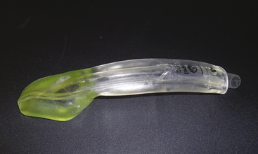
The I-Gel (Intersurgical, Liverpool, NY) is a single-use cuffless supraglottic device made from a thermoplastic elastomer that helps create a seal of the pharyngeal, laryngeal, and perilaryngeal structures. Compression trauma is limited with the use of this material. The I-Gel has a gastric lumen and a built-in bite block along with a buccal cavity stabilizer that aids insertion and eliminates rotation within the oropharynx. The device is available in adult sizes 3 to 5 and accommodates nasogastric tube sizes 12 to 14 (Fig. 16-10).40
SLIPA Pharyngeal Liner
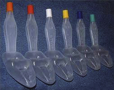
The SLIPA streamlined pharyngeal liner (CurveAir Limited, London, UK) is a hollow, cuffless, preformed pharyngeal liner. No cuff is needed for the device to seal the pharynx. The SLIPA was named because it is shaped like a slipper, with a “toe,” “bridge,” and “heel.” During insertion, the jaw is lifted forward “to negotiate the toe of the chamber past the bend in the pharynx at the base of the tongue.” The bridge fits into the piriform fossa, sealing the upward outlet at the base of the tongue. The heel anchors the SLIPA into position, sealing off the nasopharynx. The hollow bowl acts as a reservoir for secretions and aids in preventing aspiration as a result of regurgitation. The nonlatex SLIPA is available in six sizes related to patient height and the dimension across the thyroid cartilage. Preformed indentations in the SLIPA help spare the hypoglossal nerve from compression, and the stem aids in placement without the need for fingers to be inserted in the mouth. This is a single-use device (Fig. 16-11).41
Cobra Plus
The Cobra Plus (Engineered Medical Systems, Memphis, TN) is a single-use, nonlatex supraglottic device designed positioned in the hypopharynx. The device has an airway tube, standard 15-mm connector, and a distal ventilation port surrounded by a slotted port cover that helps prevent the soft tissue and the epiglottis from obstructing the ventilation port. In addition, the Cobra Plus has the ability to monitor the patient’s core temperature, has a distal carbon dioxide sampling port, and is available in pediatric sizes. Fiberoptic intubation can be facilitated by this device, which is available in adult and pediatric sizes, ½ to 6 (Fig.16-12).42
Aura
The Aura (Ambu Inc., Ballerup, Denmark) is a supraglottic device that has a preformed anatomic curve that simulates human anatomy. This device has no epiglottic bars on the anterior surface of the cuff and has a built-in bite block and an easily removable 15-mm connector that aids in fiberoptic intubation. The Aura comes in reusable and disposable designs, and Ambu recently introduced a wire-reinforced flexible device and devices with straight airway tubes. The Ambu devices are available in sizes 1 to 6, and the reinforced device is available in sizes 2 to 6 (Fig. 16-13).42
Obturator and Gastric Tube Airways
Although direct laryngoscopy and tracheal intubation were the standard of airway management in the 1960s, especially in patients who were at risk for gastric content aspiration, concerns regarding out-of-hospital resuscitation were dominant in the emergency medicine literature.39 Failure of tracheal intubation outside the hospital was common. Recognizing that blind passage of a device into the mouth typically resulted in esophageal intubation, devices that took advantage of this observation flourished. The esophageal obturator airway (EOA) was the first such device.43 The EOA consisted of a face mask with a blind-ended, cuffed, esophageal obturator, or blocker. Once placed in the esophagus, ventilation could be achieved via perforations in the obturator tube as long as the proximal mask was tightly sealed on the face. Proliferation of EOA use resulted in many criticisms, including reports of accidental tracheal intubations with failure to ventilate, esophageal perforation, gastric insufflations because of cuff failure, and distortion of upper airway anatomy.11 A modification of the EOA, the esophageal gastric tube airway (EGTA), allowed emptying of the stomach. The concept of the EOA and EGTA was further transformed by Dr. Michael Frass, who substituted a pharyngeal cuff for the poorly fitting face mask of the original devices.
Combitube
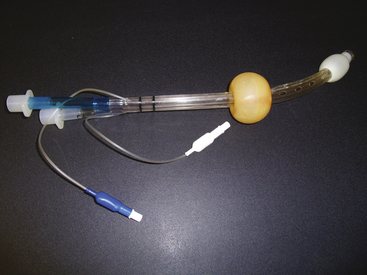
The Combitube (Tyco Healthcare [now Covidien], Mansfield, MA) was introduced in 1987 as a substitute for tracheal intubation, especially when trained personnel, proper equipment, or adequate patient access was not available for emergency airway management. The Combitube also has been used for routine anesthetic delivery44,45 and is available in two sizes: the 37 Fr size is for patients 120 cm to 180 cm in height, and the 41 Fr size is for patients taller than 180 cm. The Combitube is a double-lumen airway composed of a pharyngeal lumen and a tracheoesophageal lumen. The pharyngeal lumen has a standard 15-mm connector at the proximal end (outside the patient) but ends blindly. At the level of the pharynx are multiple perforations that when properly placed are juxtaposed to the laryngeal inlet. The second lumen also has a standard 15-mm connector at the proximal end but terminates with a patent lumen distal to the pharyngeal perforation of the pharyngeal lumen. When properly placed, the distal end of the tracheoesophageal lumen lies within the esophagus. Two cuffs seal the airway; an oropharyngeal balloon lies proximal to the pharyngeal perforations, just posterior to the hard palate. When inflated, the balloon presses ventrocaudally against the tongue and dorsocranially against the soft palate. The distal cuff lies just proximal to the open end of the tracheoesophageal lumen (Fig. 16-14). This configuration allows placement of the distal end of the Combitube into the esophagus (95% of blind placements) or into the trachea. In the esophageal position, which is assumed a priori on first placement, ventilation of the lungs occurs via the pharyngeal perforations; the operator ventilates via the pharyngeal lumen proximally, which is colored blue. In this position, projectile decompression of the stomach via the tracheoesophageal lumen often occurs. Attesting to the ability of the Combitube to decompress the stomach is a “deflation elbow” that can be attached to the esophageal lumen prior to Combitube insertion to prevent soiling.
If tracheal position of the distal Combitube occurs, which can be presumed if ventilation via the pharyngeal lumen is inadequate, the operator switches ventilation to the clear plastic tracheoesophageal lumen. In addition, the Combitube can be inserted with the patient’s head in a neutral or extended position; the classic “sniffing” position may impede insertion. In general, the patient’s airway reflexes must be obtunded for adequate insertion, which may be performed blindly or with a standard laryngosocope.
The Combitube has been left in situ for 8 hours and can be used with mechanical ventilation. Upper limits of achievable airway pressure have been recorded at 50 cm H2O. The Combitube also may be substituted with a standard tracheal tube by several techniques. The oropharyngeal cuff is deflated, and a laryngocsope or flexible fiberscope is used to achieve tracheal intubation; nasal fiberoptic intubation has also been described with minimal deflation of the pharyngeal cuff, allowing continuous ventilation during the procedure.44 Once tracheal intubation has been confirmed, the distal cuff is deflated, and the Combitube is removed. If tracheal intubation proves difficult, the pharyngeal cuff is reinflated, and ventilation via the Combitube is resumed.
A similar device released in 2006, the Rusch Easy Tube (Teleflex Medical, Research Triangle Park, NC), also was devised for either tracheal or esophageal intubation, specifically for difficult or emergent intubation. The device consists of a “large-volume pharyngeal nonlatex cuff tapering down from a dual lumen above the pharyngeal cuff to a single lumen at the tip, thereby reducing the potential for trauma to either the trachea or esophagus.” The Easy Tube is available in 28 and 41 Fr sizes. The Easy Tube is considerably smaller than the Combitube and affords a better fiberoptic view. The insertion of the Easy Tube is similar to the placement of the Combitube, and the exchange for an endotracheal tube (ETT) can be carried out using techniques described above for the Combitube.46
Endotracheal Tubes
The art of endotracheal anesthesia is more than 100 years old. The first orotracheal intubation anesthetic was in 1880 by Glasgow surgeon Sir William Macewen.47 In 1901 the German physicist Franz Kuhn modified the ETT for an easier intubation.48
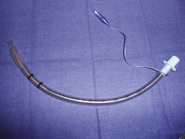
Several indications exist for ETT intubation. Some important indications for intubation are oxygenation and positive-pressure ventilation, pulmonary toilet, and airway protection. ETTs initially were made of rubber for multiple uses; however, these devices were prone to kinking, and they were unsuitable for patients sensitive to latex. ETTs today are made of many materials, although the most commonly used material is PVC. PVC is inexpensive, and the tubes conform to patient anatomy through thermoplasticity and are more resistant to kinking.49 ETTs must conform to the American Society for Testing and Materials International (ASTM) standard, which includes specifications for inside and outside diameters, distance markers from the tip, material toxicity, angle and direction of the tip, size and shape of the Murphy eye, and radius of the tube curvature.50 ETTs may either be cuffed or uncuffed; cuffs provide a seal between the ETT and trachea, thereby protecting the trachea from gastric contents. ETTs in use today have high-volume, low-pressure cuffs that disperse force on the tracheal tissues.
Armored Tubes
Armored tubes, both anode or flexometallic, have a reinforced metal or nylon wire wound in a spiral throughout the shaft of the tube. These tubes are resistant to kinking and compression and often are used in head, neck, and tracheal surgery and in positions in which the neck is flexed. A disadvantage of this tube construction is that once it is kinked or compressed, it does not revert to its original shape; this can result in airway obstruction (Fig. 16-15).41
Preformed Tubes
Preformed tubes, such as Ring-Adair-Elwyn (RAE) tubes, have a preformed bend and are available for both oral and nasal intubations to prevent the ETT from hindering access to the surgical field. They are predominantly used in oromaxillofacial and nasal procedures (Fig. 16-16).41
Parker Flex-Tip Tube
The Parker Flex-Tip ETT (Parker Medical, Highlands Ranch, CO) is designed to facilitate the passage of the tube into the trachea during flexible fiberoptic-aided laryngoscopy. Clefts between the bevel of standard tracheal tubes and the fiberscope may result in entrapment of the right arytenoid cartilage, vocal folds, or other structures. However, the bevel of the Parker Flex-Tip tube decreases the distance between the fiberoptic scope insertion cord and the ETT, thereby increasing the success of first-attempt passage of the ETT.41
Hunsaker Mon Jet Tube
The Hunsaker Mon Jet tube (Xiomed, Jacksonville, FL) is designed for elective jet ventilation. The tube consists of a flexible, collapsible cage that positions the distal end of the tube in a midline tracheal position, a 3-mm laser-resistant shaft with a stylet, and a carbon dioxide sampling line. The Hunsaker tube has a Luer-lock top that allows for connection to a jet ventilation device. The carbon dioxide sampling line allows for monitoring of the end-tidal carbon dioxide or airway pressure in an effort to avoid barotrauma. This tube can be used with both carbon dioxide and yttrium-aluminum-garnet (YAG) lasers (Fig. 16-17).51
Laryngoscopy
Since the 1940s, the most common device used to facilitate tracheal intubation has been the direct laryngoscope (DL). A rapid, easily learned, and highly successful technique, direct laryngoscopy has universal acceptance. The practice of direct laryngoscopy is one of creating a nonanatomic access through a line of sight from the operator to the larynx. With the introduction of anatomically compliant devices (discussed below), the DL is likely to have reduced importance in the future.
All direct laryngoscopes have three basic components: the handle, the blade, and the light source. Although the modern DL in use by the anesthesiologist is based on a right-angle relationship of the handle and blade (with some exceptions), U-type configurations also have been produced and remain popular in otolaryngology. Although fixed-handle blades have been used in the past, most modern systems use a folding latch connector between the two, which also acts as a switch for powering the source of illumination by a variety of mechanisms. Adaptors that can be placed between the handle and blade allow the right angle to be modified to various clinical situations.
The first direct laryngoscopes used external light sources—direct sunlight, head mirrors, and headlamps—to illuminate the larynx.52 In 1902, Einhorn developed a lightbulb carrier that could be mounted on the blade. In 1907, Jackson developed a blade that used this carrier to provide distal illumination. In 1913, batteries were incorporated into the handle by Janeway. Although the batteries in the handle/lightbulb-on-blade configuration were standard for more than 80 years, the GreenLine DL system (SunMed, Largo, FL) incorporates the entire light-producing mechanism, batteries and light bulb, into the handle. Light transmission to the larynx occurs via a rigid, steel-encased fiberoptic cable. This system offers the advantages of keeping the electrical components in a sealed case and reducing the exposure of the patient to a hot light source.53
The DL blade is used to create an axis of visualization of the larynx. The blade spatula compresses the tongue into the mandibular space, while the flange (if present) is used to move the tongue laterally and create a visual lumen. The spatula may be straight, curved, or angular, but the resulting lumen must be a straight line. Flanges have been designed in a variety of cross-sectional shapes that include C, U, and O shapes (the O shape is a completely enclosed tube). The cross-sectional height of the flange is termed the step.
The distal end of the blade is referred to as the tip and is used to elevate the epiglottis. The tip may be placed either underneath the epiglottis, to lift it directly, or in the vallecula, where stretching of the glossoepiglottic ligament causes elevation. The tip generally is blunt and thickened to reduce trauma.
Although more than 50 DL blades have been designed and marketed, the straight Miller blade and curved Macintosh blade are the predominant ones in clinical use. In lieu of a detailed discussion of each, the unique properties of various blades are highlighted in Box 16-1.
Indirect Laryngoscopy
Advances in the engineering of light-transmitting fibers in the 1950s led to the development of tracheal intubation devices that used indirect imaging of the larynx; a direct line of sight from the operator to the patient larynx was no longer required. Subsequent to this development, the miniaturization of electronics allowed the development of cheaper and more durable devices.
Suspension Laryngoscopy
Suspension laryngoscopy is done with the patient under general anesthesia and consists of a hollow scope used to expose the patient’s pharynx and larynx. The laryngoscope is suspended by an external support that allows the surgeon’s hand to be free for procedures.
A Dedo scope, a U-shaped scope used during suspension laryngoscopy, is designed to allow examination of the vocal cords at the anterior commissure in patients who have challenging airways. These scopes can be adapted to allow exposure of the airway with microscopes and fiberoptic light sources, tissue removal with lasers, adaptation to video for teaching purposes, and oxygenation and ventilation with a Venturi device. These scopes typically are used by otorhinolaryngologists.57
Devices
The concept of the fiberscope was first considered in 1954 with the development of glass fiber bundles. Light entering one end of a glass rod undergoes repeated reflections until it emerges from the distal terminus, and small amounts of light are lost with each reflection in the rod. When the glass rod is heated, it may be stretched to a diameter of less than 25 μm. At this diameter, the glass becomes flexible. Reflections of transversing light occur at approximately 10,000 per meter. During transmission down a single fiber, all incoming light is blended to a single, averaged color. Therefore a complex image cannot be transmitted down a single glass fiber; rather, a single colored “pixel” is transmitted. By fusing the terminals of many fibers (e.g., 10,000 to 30,000) and applying an image-magnifying lens, a complex image may be focused onto the objective end of the bundle. The pixelated image is then transmitted to the operator’s fused terminus, where a second lens can be used to produce a focused image. The greater the number of fibers and the smaller their size (albeit >8 μm), the higher the resolution of the image. The fiber bundle is fused only at the two termini, maintaining the flexibility of the rest of the bundle. The bundle also must be coherent—that is, the fiber arrangement must be identical at the two termini—if the pixelated image is to be reproduced from one end to the other. Noncoherent fibers, which are less expensive to produce, may be used for applications in which an image is not transmitted, such as with an illuminating source. A second layer of glass, 1 μm thick and with a lower refractive index than the fiber, is fused to the individual fibers; this is termed the cladding, and it reduces the amount of light lost with each intrafiber reflection and prevents interfiber light contamination.
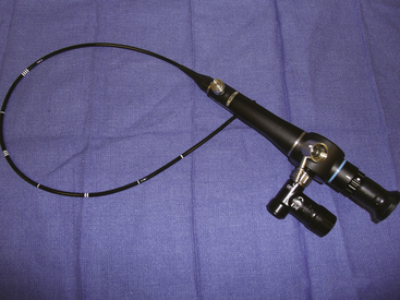
The fiber bundle described above comprises the primary functional element of the flexible fiberoptic intubation scope. The remaining elements add functionality. All elements are bound together within a protective, waterproof plastic cover and together are referred to as the insertion cord (Fig. 16-18).
Optical Quality
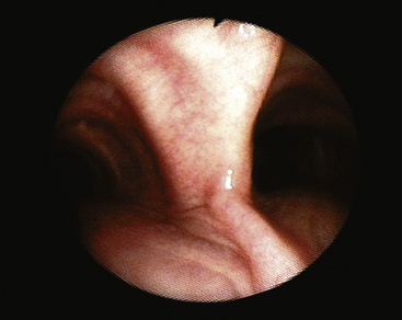
As mentioned, the resolution of the image delivered to the operator at the eyepiece or video screen (Fig. 16-19) depends on the number of fibers as well as the fiber size. The objective (distal insertion cord) has a fixed focus lens. The depth of field is typically 3 to 5 mm. When the tip-bending mechanism is in the neutral position, the field of view is cone shaped. The field of view of the typical fiberscope is 55 to 120 degrees, and the conical field of view may be swung in an arch around the hinged angle.
Light Bundles
As previously mentioned, illumination is provided by noncoherent fiber bundles that travel with the image bundle to bring light to the object. Modern fiberscopes have one or two such bundles. Proximally, the light fibers are supplied with an external light source or battery-powered sources.
Distal Tip–Bending Mechanism
Anterior-posterior bending of the distal tip of the insertion cord is achieved by manipulation of two fine wires embedded in the respective surfaces of the cord. A lever in the handle of the fiberscope is used to tighten or slacken the opposing wires, causing motion of a multifacet joint near the distal end; attempting to bend the tip against force may result in wire damage and inability to direct the tip. Anterior-posterior tip deflection may be purposely asymmetric (i.e., flexion in one direction may be greater than in the opposite direction). The degree of flexion may be up to 180 degrees and depends on the manufacturer and model of the fiberscope.
Working Channel
Most adult intubation fiberscopes house an open lumen that runs the length of the fiberscope from the distal tip to the handle, which also houses the directional controls and proximal optical elements. The working channel of newer fiberscopes has three apertures: one at the distal end of the insertion cord and two on the fiberscope handle. The most proximal aperture, or port, is typically fitted with a valve that allows intermittent application of suction or compressed oxygen. The midport, also on the fiberscope handle, typically has a Luer-lock fitting; syringes for drug or lavage delivery, diaphragm-sealed access ports, biopsy and foreign body retrieval loops, or cleaning brushes may be attached or inserted into this port. Because the working channel is not integral to the primary operation of the fiberscope, it often is eliminated in favor of smaller insertion cord diameters, such as in pediatric models.54
Charge-Coupled Devices
Although indirect optical intubation devices have historically used glass fibers to provide image conveyance around anatomic angles, new instruments have incorporated electronic technology to improve image quality and device durability. Charge-coupled device (CCD) technology uses a two-dimensional array of light-sensitive capacitors, which sit at the objective end of the “scope.” These light-sensitive silicone semiconductors are buried under multiple layers of polysilicon charge-coupled “gates” that propagate the signal to an interpreting circuit. As photons pass through the gates and strike the semiconductors, a charge is created. The number of photons striking an individual semiconductor is proportional to the intensity of the light. Each semiconductor in the array is electrically isolated from its neighbor and acts as a pixel generator of the final image. In the highest quality imagers, three CCD panels detect the three primary colors, which requires a large area. In most medical and lower cost systems, color is instead detected by the incorporation of a Beyer pattern, which consists of alternating red-green and green-blue filters. These systems can be designed to be significantly more compact than the three-CCD system. Under this scheme, color information for each pixel is determined by interpolation of the signal from its neighboring pixels. For example, a pixel under a red-green filter will determine the correct color information by examining the intensity of light striking its neighboring pixels beneath red-green and green-blue filters.
A CCD system eliminates the need for fragile glass fibers and can give excellent clarity because of the minimal elements between the objective and the chip. At the time of this writing, flexible CCD intubation scopes were four to five times more expensive than a traditional fiberscope.54
Rigid Laryngoscopes
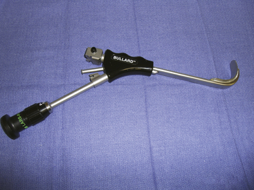
The Bullard laryngoscope (Gyrus ACMI, Southborough, MA) is the prototypical anatomically shaped rigid fiberscope. This device consists of a blade 1.3 cm wide and 13.2 cm in length with a fixed anterior curve (3.4 cm radius) meant to replicate the typical adult oral-to-pharyngeal anatomy. To provide indirect imaging around this angle, a fiberoptic bundle is embedded on the posterior surface of the blade, which is 0.64 cm thick. The objective lens is 2.6 cm from the distal end of the blade. Parallel to the embedded image fiber is a 3.7-mm working channel and an illumination fiber bundle. The operator handle with eyepiece and adjustable diopter, standard laryngosocpe handle latch with recessed light bulb, and working channel aperture with Luer-Lock fit a nonmalleable tracheal tube stylet that follows the underside of the blade. The distal 2 cm of the stylet is angled toward the midline. When viewed through the eyepiece, the stylet tip can be seen to direct the path of the tracheal tube as it is extended off the stylet. Three Bullard scope accessories include a hollow tracheal tube stylet, a single-use blade extender, and an external light source cable adaptor. Pediatric and adult sizes are available (Fig. 16-20).
WuScope System
The WuScope (Pentax Medical, Tokyo) is similar to the Bullard laryngoscope in that is uses a fixed, shaped blade assembly meant to follow intrinsic patient anatomy. The fiberoptic elements, image and illumination, are provided by a separate, flexible fiberscope (Olympus LF-1, LF-2, or ENF-P3 rhinoscope) that follows a dedicated groove manufactured on the lateral aspect of the blade assembly. A working channel closely parallels the fiberscope groove to provide lens-clearing suction or oxygen insufflation. The WuScope handle is conical and holds the fiberscope handle. The two-blade assembly is attached to the distal handle to produce a channel through which the tracheal tube passes. Optionally, a suction catheter may be passed through the tracheal tube and used as a guide for intubation. Once the glottis is visualized and the tracheal tube has been passed, the blade is disassembled and removed from the mouth. Nasal intubation has been described with the WuScope; the tracheal tube is passed though the nose and into the pharynx, the blade is assembled around the tracheal tube, the glottis is visualized, and the tracheal tube is passed.55
Upsher Scope
The Upsher scope and Upsher Ultra scope (Mercury Medical, Clearwater, FL) consist of a C-shaped stainless steel blade encasing fiberoptic bundles, channeled ETT guide, horizontal flange beyond the tube-guided channel, distal lens, and proximal eyepiece. The earlier Upsher scope had an eyepiece that could be focused. The later version, Upsher Ultra, does not have an eyepiece that can be focused, thereby allowing the device to be fully immersible for cleaning.
The device is placed with the patient’s head in the neutral position. A small degree of neck flexion may aid in elevating the epiglottis to improve glottic visualization. The Upsher scope can negotiate a 15-mm mouth opening and accommodates size 7.0, 7.5, and 8.0 ETTs. The Upsher Ultra differs from the original scope in that the C-shaped steel blade now has a curvature of almost 90 degrees to more closely approximate the curvature of the base of the tongue and oropharynx. In addition, the Upsher Ultra has a power handle for adaptation to a fiberoptic light source, a snap-on camera that adapts to the eyepiece for remote viewing on a monitor, and the ability to insufflate oxygen down the ETT during intubation, which can be facilitated by passing a bougie down the ETT through the glottis opening and sliding the ETT over the bougie.56
Bonfils-Brambrink Endoscope
The Bonfils-Brambrink (infant) endoscopes (Karl-Storz)are optical stylets similar to the Levitan (Clarus Medical, Golden Valley, MN) and Shikani endoscopes. These are rigid-shaft endoscopes with a distal-end fixed deflection. The optical and illuminating elements are encased in a stainless steel shaft, and one model incorporates a working channel. The Bonfils devices also have an adjustable-angle eyepiece to improve ergonomic function. Unlike other optical stylets, the Bonfils-Brambrink endoscopes use a retromolar approach similar to that proposed for the Henderson laryngoscope blade. The endoscope, with a loaded tracheal tube, is guided lateral to the molars. A chin lift or chin-tongue lift maneuver increases the pharyngeal space. Once the pharynx is reached, the scope is rotated until the larynx can be viewed. The tracheal tube is then guided off the stylet and into the larynx under indirect visualization.58
Lighted Malleable Stylets
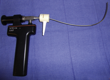
The Shikani optical stylet (Clarus Medical, Minneapolis, MN) is a high-resolution fiberoptic stylet that has a preformed curvature. The metallic casing of the distal scope is malleable and may be shaped by the user. The Shikani has an integrated oxygen port for insufflation and an adjustable tube stop. Made of stainless steel, it is available in adult and pediatric sizes and can be used as an adjunct to direct laryngoscopy or as an independent device. The light source can be a laryngoscope handle or an external cabled light source. A complementary metal oxide semiconductor system is now available (Fig. 16-21).
Levitan
The Levitan (Clarus Medical) is a high-resolution fiberoptic stylet with a malleable distal end. It has an integrated oxygen port, but it does not have an adjustable tube stop. The Levitan also can be used as an adjunct to direct laryngoscopy or as an independent device. It is available only in adult sizes.
Foley Flexible Airway Scope Tool
The Foley flexible airway scope tool (Clarus Medical) is a flexible stylet with a tip that cannot be directed. This device is used as an adjunct to aid tracheal intubation through an intubating laryngeal mask; it can be used for extubation as well. This device also has been adapted for nasal intubation.
Clarus Video Airway System
This system combines a malleable stylet with a 4-inch liquid crystal display (LCD) screen for video assistance. An optional flexible stylet is available.59
Alternative Rigid Imaging Devices
An early criticism of the LMA Fastrach was the blindness of the tracheal intubation.60 Although recognized as being a significant advance in the difficult airway armamentarium, especially with its combined faculities of ventilation and intubation, the principle of visualization for verification of glottic intubation was violated.61 An advanced Fastrach, the CTrach (LMA North America), was introduced in 2005 (Fig. 16-22). The CTrach has a silicone-coated stainless steel barrel and silicone mask identical to that of the Fastrach. Two embedded fiberoptic cables, an image cable and an illumination cable, descend on the lateral aspects of the barrel, from a magnetic latch connector on the proximal barrel, and terminate in the Fastrach-like bowl of the CTrach at a point just distal to the barrel orifice. This objective lens and illumination source position lies directly under the lower third of the epiglottic elevating bar (EEB). To allow illumination and visualization, a window has been cut into the EEB. An LCD display encased in a rechargeable monitor connects with the magnetic latch to give a view of the structures beyond the EEB. The view angle of the CTrach lens is unique among airway devices in that it occurs from a posterior position. Because of this arrangement, the arytenoids, aryepiglottic folds, tracheal tube barrel, and glottic aperture are all often visible during the act of intubation. Contrary to this interesting and useful view is the effect of gravity on secretions, which may pool near the lens. The fiberoptic elements comprise a bundle of 10,000 plastic fibers that gives adequate resolution but is not as clear as many other fiberoptic devices.
The CTrach is inserted in much the same way as the Fastrach. After adequate anesthesia, either general or topical, the barrel handle is held on the chest as the lubricated and completely deflated distal mask tip is placed against the hard palate (this initial position prevents monitor attachment). A backward, sweeping, rotational movement introduces the mask into the hypopharynx. Either in mid sweep or after full insertion, the monitor is attached; if placed mid sweep, the passing structures can be appreciated. Next, the mask is inflated, and the glottis should be appreciated at this time. If not, maneuvers common to those used for the Fastrach can be applied, such as Chandy’s maneuver (lifting of the mask off the posterior wall) or an up-down maneuver (a 6-cm outward and return “replacement” of the inflated mask).62 Observation via the monitor during these maneuvers may reveal the location of the laryngeal anatomy.
As with the Fastrach, the CTrach functions adequately as a supraglottic ventilation device. This can be achieved in initial placements regardless of the fiberoptic view.63 Failure to ventilate adequately and with appropriate airway pressures is most often corrected with the up-down maneuver or Chandy’s first maneuver,62 in which the barrel handle is manipulated to find an ideal optical position.
The imaging capability of the CTrach offers the operator information for diagnosing misplacement during failed Fastrach intubation attempts; a down-folded epiglottis, a distant epiglottis/larynx, and an arytenoid entrapped by the EBB can be seen and corrected with manipulation or CTrach size change.64 However, failure to obtain an adequate or any image does not preclude adequate ventilation or attempts at intubations.
GlideScope
The GlideScope (Verathon Medical, Bothell, WA; Figs. 16-23 and 16-24) uses an acutely angled blade (60-degree arch) that curves around the base of the tongue. A high-resolution CCD color camera is integrated near the distal tip to give the operator a view of the airway anatomy beyond the curve. Illumination is provided by diodes, eliminating the need for an external light source, and the system also has antifogging capability. Power is provided through a cord emanating from the handle and attached to a portable LCD screen, and both alternating current (AC) and battery-powered units are available. Because of the location of the camera, significant alignment of the oral and pharyngeal axes is unnecessary.65 The GlideScope has been proven superior to the direct laryngosocpe blade in pediatric and obese patients, those with cervical spine disease, those with a high Cormack and Lehane score (on routine laryngoscopy), patients outside the operating room, as well as where portability is important. Both awake and anesthetized techniques have been used. In one large study, laryngeal view scores of I or II were recorded in 99% of patients, far above what is expected with direct laryngoscopy.66 Although the laryngeal view may be almost universally achieved, tracheal intubation had a failure rate of 3.7%, despite a grade I or II laryngeal view, in the uncontrolled clinical series.65 Although the procedure of GlideScope insertion into the airway is familiar to the anesthesiologist, in that it is similar to the procedure of direct laryngoscope placement, ETT placement differs; because of the acute angle of the blade and the fixed shape of the ETT, hand manipulation occurs in an unaccustomed fashion.
Unlike direct laryngoscopy, the GlideScope is inserted in the midline. Airway structures, such as the uvula and epiglottis, should be viewed as the GlideScope moves through the airway. Most investigators recommend that the tip of the blade be placed anterior to the epiglottis, and an ETT with a nonmalleable stylet is recommended. The ETT should be preshaped prior to laryngoscopy: a 60-degree curve can be achieved, similar to that of the GlideScope blade, but operators may find their own ideal contour. Maneuvers that can increase the success of the GlideScope include external laryngeal pressure, sharper angle shaping of the ETT, and placement of an intubating bougie under GlideScope observation and slight withdrawal of the GlideScope blade. A preformed, rigid stylet developed for use with the GlideScope is available, as is a digital video recorder to record intubations, confirm tube placement, and facilitate teaching. Verathon has released a disposable version that uses single-use blades over a CCD baton. Versions that allow video recording and USB drive capability are also available, along with four blade sizes (Table 16-5).65
McGrath Laryngoscope
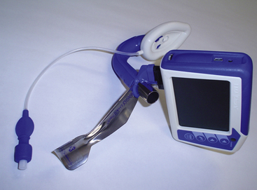
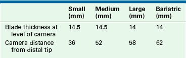
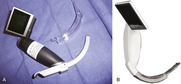
The McGrath laryngoscope (Aircraft Medical, Edinburgh, UK) is a portable rigid glottic imaging device that replicates the look and feel of the direct laryngoscope but with a blade angulation similar to that of the GlideScope. The McGrath Series 5 (Fig. 16-25, A) uses a handle and blade configuration reminiscent of the direct laryngoscope but with several additions: a color microcamera is fitted on the distal aspect of a reusable “camera stick,” to which a single-use polymer blade is fitted. The handle-to-tip distance is adjustable. The VGA Digital Imaging Sensor transmits the laryngeal image to a flat-panel screen mounted on the handle. The McGrath Mac Scope has a less angulated blade of fixed length (Fig. 16-25, B); whereas the Series 5 is an indirect visualization device, the McGrath Mac Scope is meant to allow direct or indirect laryngeal vision techniques. The maximum interdental width of the blade is 14 mm. Although data are limited, several abstracts favorably compare intubation success with the McGrath to the GlideScope.59
Airtraq
The Airtraq (Prodol Meditec, Bilbao, Spain) is a channeled, portable optical device. The optical channel contains prisms, and the guiding channel accommodates the ETT. The device has an in situ antifogging mechanism that activates within 60 seconds, and the internal light source lasts 90 minutes. The Airtraq is inserted midline, and the glottis can be viewed through an eyepiece, adapted to a monitor, or visualized through an optional wireless camera and monitor. The Airtraq is available in both pediatric and adult sizes, and variations of this single-use device include a double-lumen tube and nasotracheal intubation devices (Fig. 16-26).59
Tracheal Tube Stylet Devices
As an aid to direct or indirect laryngoscopy, several devices have been introduced for use during tracheal intubation, intubation verification, extubation, and tracheal tube exchange. Although they differ in design and capabilities, all essentially function as stylets. These devices and their distinctive features are listed in Table 16-6.59
Alternative Intubation
air-Q Intubating Laryngeal Mask
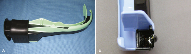
The air-Q (Mercury Medical) is an intubating laryngeal airway with a hypercurved airway tube, large mask cavity, and recessed anterior portion. The circuit adaptor is removable, and intubation can be achieved by a large airway tube that is not easily kinked. Intubation is most often described with adjunctive use of a fiberscope. Removal of the air-Q after intubation is facilitated by a removal stylet. The air-Q also has a built-in bite block and is available in adult and pediatric sizes and as reusable and disposable units (Figs. 16-27 and 16-28).59
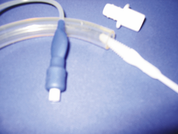
Lightwand
Illumination Technique
The first report of the use of transcutaneous illumination, a light source in the airway seen externally, to facilitate tracheal intubation was described in 1959 by Yamamura and colleagues.67 The transillumination technique relies on the relatively superficial position of the laryngeal tissues in the neck compared with the esophagus. A light source in the larynx produces a well-defined illumination over the neck, typically just below the thyroid prominence; the same light source in the esophagus produces a diffuse glow. The advantage of using a lighted stylet in this manner is that it is independent of visualization of the glottis, a blind technique, and can be successfully used in the “wet” or bloody airway. Several devices are available (Table 16-7).
TABLE 16-7
| Device | Manufacturer |
| Trachlight | Laerdal Medical, Stavanger, Norway (discontinued 2009) |
| Fiberoptic intubation stylet | Benson Medical Industries, Markham, Ontario, Canada |
| Flexilume (single use) | Plastic Specialties, Industry, CA |
| Tube-Stat (single use) | Medtronic, Minneapolis, MN |
| Fiberoptic lighted stylet | Fiberoptic Medical Products, Allentown, PA |
The disadvantages to this technique are that it is a blind intubation technique facilitated by reducing ambient light: some devices are short (Tube-Stat [Medtronic, Inc., Minneapolis, MN] and Flexilume [Plastic Specialties, Industry, CA] are 25 cm) and may result in inadvertent extubation, and some require two hands to operate the light and place the tube, and the light beam is directed forward (Tube-Stat, fiberoptic lighted intubation stylet [Benson Medical Industries, Markham, Ontario, Canada], fiberoptic lighted stylet [Fiberoptic Medical Products, Allentown, PA]) as opposed to anteriorly (Trachlight; Fig. 16-29).
The Trachlight (Laerdal Medical, Stavanger, Norway), which is no longer manufactured, was specifically marketed for lightwand intubation. It is a reusable device consisting of three parts: a handle with battery pack, a flexible guide with lighted distal tip, and a malleable stylet. The Trachlight is powered by three AAA alkaline batteries. Other features include a locking clamp that holds the tracheal tube in place on the stylet until intubation is complete; a timing device, which causes the light to blink after 30 seconds; and an adjustable handle to accommodate varying tracheal tube lengths. The brightly lit tip will achieve a maximum surface temperature of 60° C, and it projects anteriorly.
Minimally Invasive Airway Techniques
Access to the airway through the cricothyroid membrane, cricotracheal ligament, or intratracheal ligaments increases the clinician’s options in both elective airway management and airway rescue. A variety of devices are available.
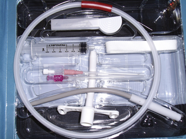
Cook Retrograde Wire Intubation Kit
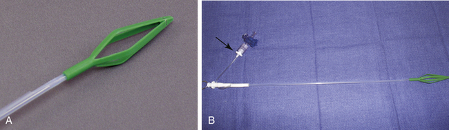
Retrograde intubation was described as early as 1960. The technique involves the passage of a catheter or wire via a percutaneous needle through the larynx or trachea and out the upper airway. A tracheal tube can then be threaded over the wire and into the larynx. The catheter or wire is then removed, leaving the tracheal tube in situ.59 The technique can be awkward if the correct equipment is not immediately available. Kits such as the Cook Retrograde Wire Intubation Kit (Cook Medical, Bloomington, IN) are helpful in this regard. The basic elements of the kit are a 110-cm (0.032-inch) wire and a stainless steel percutaneous needle. This kit also contains a 20-gauge angiocath that may be used instead of the stainless steel needle, a clamp for securing the wire at the puncture site, and a Cook Airway Exchange Catheter (AEC). The Cook AEC can be used to significantly improve the technique, helping overcome two of the most significant procedural difficulties. First, by placing the AEC over the retrograde wire prior to placement of the tracheal tube, the gap that normally occurs between the tracheal tube and the wire is obliterated. This reduces or eliminates hang-up of the tracheal tube on the vocal cords. Second, because the AEC is threaded completely into the larynx and is graduated with centimeter markings, the depth of the tracheal tube passage into the airway can be measured.59
Percutaneous Cricothyrotomy
Melker Emergency Cricothyrotomy Catheter Kit
The Melker Emergency Cricothyrotomy catheter set (Cook Medical) is designed for emergency airway access when intubation and ventilation are not possible. The cricothyroid membrane is located with an 18-gauge introducer, and air is aspirated to confirm placement. Next, an Amplatz extra-stiff guidewire is placed, and dilation of the tract follows with a curved dilator. Lastly, a radiopaque airway catheter with a 15-mm adaptor is fed over the guidewire, using a Seldinger-type technique (Fig. 16-30).59
Melker Cuffed Emergency Cricothyrotomy Catheter Kit
This kit functions the same as the Melker Emergency Cricothyrotomy Catheter Kit, except the airway catheter has a cuff that allows positive-pressure ventilation in much the same way as an ETT. This cuffed version can be used for short general anesthetic cases. However, the cricothyrotomy does not function as a tracheotomy, and prolonged use of the cricothyrotomy may damage the laryngeal cartilage.59
Pertrach Emergency Cricothyrotomy Kit
The Pertrach emergency cricothyrotomy kit (Engineered Medical Systems) is used for cricothyrotomy or tracheotomy in an emergency situation. Rather than using the Seldinger technique, this device uses “splitting needles.” Rather than cutting, the splitting needle divides the tissue, which results in less bleeding and scarring. This device is available cuffed or uncuffed in adult and pediatric sizes.59
Quicktrach Emergency Cricothyrotomy
The Quicktrach emergency cricothyrotomy device (VBM Medizintechnik, Sulz, Germany) is a preassembled kit used for securing the airway emergently. The device has a built-in stopper to prevent posterior perforation of the trachea. A precision-beveled needle allows insertion into the airway without the use of a scalpel, which results in less bleeding. The Quicktrach is available in pediatric and adult sizes, cuffed and uncuffed.
Ravussin Transtracheal Jet Ventilation Catheter
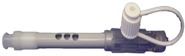
The Ravussin Transtracheal Jet Ventilation Catheter (VBM Medizintechnik) uses a stainless steel needle that allows easy puncture and kink-free insertion. The needle is covered with a Teflon catheter that is anatomically curved and allows for laser surgery. The catheter has three holes that facilitate centering of the catheter during jet ventilation. A 15-mm adaptor allows positive-pressure ventilation, and a Luer lock aids manual and high-frequency jet ventilation. The catheter is available in three sizes for adults, children, and infants.59
Transtracheal Jet Ventilation
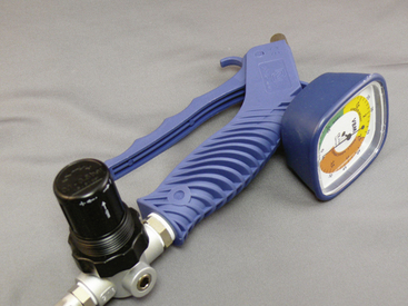
The Manujet III (VBM Medizintechnik) is a hand-held, manually operated jet ventilation valve attached to a 50-psi oxygen source. It includes a 4-mm pressure hose, Luer-lock connecting tubing (for attachment to a jetting needle or jet ETT), Endojet adapter and catheter (for ventilation with an ETT, face mask, or LMA), and pressure regulator. It is indicated for elective airway cases, when the surgeon requests no ETT, or in an urgent “can’t ventilate, can’t intubate” situation. This device can be used independently with a jetting needle or a Hunsaker Mon Jet ETT. Alternatively, the included Endojet adapter and catheter can be used through an ETT, LMA, or a face mask. This reusable device must be used in an unobstructed airway (Fig. 16-31).59
Ventrain
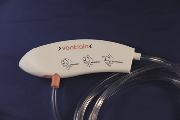
A new concept in jet ventilation is expiratory ventilatory assistance (EVA), in which the Venturi effect is used to assist gas removal during the expiratory phase. The Ventrain (Dolphys Medical, Eindhoven, The Netherlands) device uses EVA. The Ventrain is designed to be used for transtracheal rescue ventilation or electively in laryngeal surgery (Fig. 16-32). EVA may be particularly important in the rescue of a completely obstructed airway, in which the ventilation of gases must occur via a small-bore rescue catheter. Preliminary studies demonstrate that Ventrain ventilation results in superior carbon dioxide removal compared with non-EVA jet ventilation devices.
AincA Manual Jet Ventilator
The AincA manual jet ventilator (Anesthesia Associates) is similar to the Manujet III and has the same indications. The AincA has an on/off thumb control and an internal filter and can be customized to individual specifications (hose lengths, oxygen source connector, and pressure gauge).59
Enk Oxygen Flow Modulator
Unlike the above-mentioned devices, the Enk oxygen flow modulator (Cook Medical) is portable, self-contained, and disposable. It is indicated in emergency airway situations when a jet ventilator is not available. The Enk allows manually controlled oxygen flow by portholes on the oxygen flow modulator, which are finger occluded to start gas flow. The device can attain nearly 14.7 psi (1 atm) (Fig. 16-33).59
Cook Emergency Transtracheal Airway Catheters
These coil-reinforced, nonkinkable catheters are used for emergency access through the cricothyroid membrane when intubation and ventilation are precluded. These 6 Fr catheters have a 2-mm internal diameter and are available in two lengths. They are superior to angiocatheters because flow is not occluded by kinking (Fig. 16-34).59
Positioning Pillows
In morbidly obese patients, it is often difficult to stack pillows and blankets to optimize neck extension and potential airway exposure. The Troop device (Mercury Medical) is a sturdy foam pillow designed to place the patient in a head-elevated laryngoscope position. The pillow is for single use only. A head pillow and accompanying arm board pillows also are available.
Pi Pillow Positioning Device
The Pi pillow positioning device (American Eagle Medical, Coram, NY) is a two-part pillow with a base and a removable pad. Both parts together allow comfortable patient positioning. Once general anesthesia is induced, the top pad is removed and the patient’s head achieves a “sniffing” position. The Pi pillow comes in single-use and reusable forms and five sizes that range from pediatric to morbidly obese. Once a sniffing position has been achieved, the pillow also facilitates central line placement, Swan Ganz placement, and interscalene blockade. The pillow also facilitates surgical procedures such as thyroidectomy and laryngectomy.
References
1. Sykes W. Essays on the first hundred years of anesthesia. London: Churchill Livingstone; 1982.
2. Lyman H.M. Artificial anaesthesia and anaesthetics. New York: William Wood and Co; 1881.
3. Brimacombe J. Laryngeal mask anesthesia: principles and practice, ed 2. Philadelphia: Saunders; 2005.
4. Ball C., Westhorpe R. Clearing the airway: the development of the pharyngeal airway. Anesth Intensive Care. 1997;25:451.
5. Gudel A. A non-traumatic pharyngeal airway. JAMA. 1933;100:1862.
6. Brandt L. The first reported oral intubation of the human trachea. Anesth Analg. 1987;66:1198–1199.
7. Sweeny B. Franz Kuhn: his contribution to anaesthesia. Anaesthesia. 1985;40:1000–1005.
8. Westhorpe R. Kuhn’s endotracheal tube. Anesth Intensive Care. 1991;19:489.
9. Magill I. Technique in endotracheal anaesthesia. Proc R Soc Med. 1928;22:83–88.
10. Brimacombe J. Laryngeal mask anesthesia: principles and practice, ed 2. Philadelphia: Saunders; 2005. p 7
11. Brimacombe J. Laryngeal mask anesthesia: principles and practice, ed 2. Philadelphia: Saunders; 2005. p 6
12. Griffith H.R., Johnson G.E. The use of curare in general anesthesia. Anesthesiology. 1942;3:418–420.
13. Mendelson C. The aspiration of gastric contents into the lungs during obstetric anesthesia. Am J Obstet Gynecol. 1946;52:191–204.
14. IP Latto, Rosen M. Changing times: changing standards. In: Difficulties in tracheal intubation. London: WB Saunders; 2000. pp ix-x
15. Brimacombe J., ed. Laryngeal mask anesthesia: principles and practice, ed 2, Philadelphia: W.B. Saunders, 2005.
16. Brain A.I. The laryngeal mask—a new concept in airway management. Br J Anesth. 1983;55:801–805.
17. Verghese C., Brimacombe J.R. Survey of laryngeal mask airway usage in 11,910 patients: safety and efficacy for conventional and nonconventional usage. Anesth Analg. 1996;82:129–133.
18. Maltby J.R., Beriault M.T., Watson N.C., Fick G.H. Gastric distension and ventilation during laproscopic cholescystectomy: LMA-Classic vs. tracheal intubation. Can J Anesth. 2000;47(7):622–626.
19. Brimacombe J.R., Berry A. The incidence of aspiration associated with the laryngeal mask airway: a meta-analysis of published literature. J Clin Anesth. 2005;47(7):297–305.
20. Brimacombe J., Brain A., Branagan H., Spry M., Schofield J. Optimal shape of the laryngeal mask cuff: the influence of three deflation techniques. Anaesthesia. 1996;51:673–676.
21. Brimacombe J. Laryngeal mask anesthesia: principles and practice, ed 2. Philadelphia: W.B. Saunders; 2005. p 47
22. Brimacombe J. Laryngeal mask anesthesia: principles and practice, ed 2. Philadelphia: W.B. Saunders; 2005. p 48
23. Brimacombe J. Laryngeal mask anesthesia: principles and practice, ed 2. Philadelphia: W.B. Saunders; 2005. p 53
24. Langton J.A., Wilson I., Fell D. Use of the laryngeal mask airway during magnetic resonance imaging. Anaesthesia. 1992;47:532.
25. Brimacombe J. Laryngeal mask anesthesia: principles and practice, ed 2. Philadelphia: W.B. Saunders; 2005. p 57
26. Reference deleted in proofs
27. Heath M.L., Sinnathamby S.W. The reinforced laryngeal mask airway for adenotonsilectomy. Br J Anaesth. 1994;72:728–729.
28. Parry M., Glaisyer H., Bailey P. Removal of LMA in children. Br J Anaesth. 78, 1997. 337–344
29. Williams P.J., Thompsett C., Bailey P.M. Comparison of the reinforced laryngeal mask airway and the tracheal tube for nasal surgery. Anaesthesia. 1995;50:987–989.
30. Boisson-Bertrand D. Tonsillectomies and the reinforced laryngeal mask. Can J Anesth. 1995;42:857–861.
31. Brimacombe J., Keller C. Aspiration of gastric contents during use of a ProSeal LMA secondary to unidentified foldover malposition. Anesth Analg. 2003;97:1192–1194.
32. Stix M.S., O’Connor C.J., Jr. Depth of insertion of the ProSeal laryngeal mask airway. Br J Anaesth. 2003;90:235–237.
33. O’Connor C.J., Borromeo C.J., Stix M.S. Assessing ProSeal laryngeal mask position: the suprasternal notch test (letter). Anesth Analg. 2002;94:1374.
34. Brain A.I., Verghese C., Strube P.J. The LMA ‘ProSeal’—a laryngeal mask with an oesophageal vent. Br J Anaesth. 2000;84:650.
35. Brimacombe J., Keller C., Berry A. Gastric insufflation with the ProSeal laryngeal mask. Anesth Analg. 2001;92:1614.
36. Maltby J.R., Beriault M.T., Watson N.C., Liepert D., Fick G.H. The LMA ProSeal is an effective alternative to tracheal intubation for laparoscopic cholecystectomy. Can J Anesth. 2002;49(8):857–862.
37. Brimacombe J., Keller C., Fukkekrug B., et al. A multicenter study comparing the ProSeal and Classic Laryngeal Mask Airway in anesthetized, nonparalyzed patients. Anesthesiology. 2002;96(2):289–295.
38. Rosenblatt W.H., Murphy M. The intubating laryngeal mask: use of a new ventilating-intubating device in the emergency department. Ann Emerg Med. 1999;33:234–238.
39. Gaitini L., Varda S., Somri M., et al. An evaluation of the laryngeal tube during general anesthesia using mechanical ventilation. Anesth Analg. 2003;96:1750–1755.
40. Osborn I, Reinhard PK: Current concepts and clinical use of the supraglottic airway, anesthesiology news guide to airway management, ed 2, New York, 2009, McMahon Publishing, p 58.
41. Sinha P., Misra S. Supraglottic airway devices other than Laryngeal Mask Airway and its prototype. Indian J Anaesth. 2005;49(4):281–292.
42. Osborn I, Reinhard PK: Current concepts and clinical use of the supraglottic airway, anesthesiology news guide to airway management, ed 2, Mumbai, India, 2009, Medknow Publications and Media, p 54.
43. Michael T.A., Lambert E.H., Mehran A. “Mouth-to-lung airway” for cardiac resuscitation. Lancet. 1968;2:1329.
44. Gaitini L.A., Vaida S.J., Mostafa S., et al. The Combitube in elective surgery: a report of 200 cases. Anesthesiology. 2001;94(1):79–82.
45. Gaitini L.A., Vaida S.J., Somri M., Fradis M., Ben-David B. Fiberoptic-guided airway exchange of the esophageal-tracheal Combitube in spontaneously breathing versus mechanically ventilated patients. Anesth Analg. 1999;88:193–196.
46. Gaitini L., Vaida S., Somri M., Yanovski B., Toame P. Comparison of the esophageal- tracheal Combitube and Easy Tube in paralyzed anesthetized adult patients [abstract]. Anesthesiology. 101, 2004. A517
47. James C.D. Sir William Macewen and anesthesia. Anaesthesia. 1974;29:743–753.
48. Sweeney B. Franz Kuhn: his contribution to anesthesia. Anaesthesia. 1985;40:1000–1010.
49. Dorsch JA, Dorsch SE: Tracheal tubes, understanding anesthesia equipment, ed 4, Baltimore, 1998, Williams & Wilkins, pp 557–671.
50. American Society for Testing and Materials [ASTM]. Standard Specification for Cuffed and Uncuffed Tracheal Tubes (ASTM F1242-96). West Conshohocken, PA: ASTM; 1996.
51. Davies J., Hillel A., Maronian N., Posner K. The Hunsaker Mon Jet tube with jet ventilation is effective for microlaryngeal surgery. Can J Anaesth. 2009;56(4):284–290.
52. Cooper R. Laryngoscopy: its past and future. Can J Anesth. 2004;51(6):R21–R25.
53. Alberti P.W. The history of laryngology: a centennial celebration. Otolaryngol Head Neck Surg. 1996;114:345–354.
54. Ovassapian A. Fiberoptic endoscopy and the difficult airway. Raven Press; 1996.
55. Rosenblatt W.: Airway management in clinical anesthesia. In Barash P.G., Cullen B.F., editors: Clinical anesthesia, ed 6, Philadelphia, 2009, Lippincott Williams & Wilkins
56. Friedrich P., Frass M., Krenn C.G., et al. The Upsher scope in routine and difficult airway management: a randomized controlled clinical trial. Anesth Analg. 1997;85:1373–1381.
57. DedoScope, Pilling Surgical Instruments, Teleflex Medical, Research Triangle Park, NC.
58. Bein B., Worthmann F., Scholz J., et al. A comparison of the intubating laryngeal mask airway and the Bonfils intubation fiberscope in patients with predicted difficult airways. Anaesthesia. 2004;59:668–674.
59. Hagberg C.A. Current concepts in the management of the difficult airway. Anesthesiology New Guide to Airway Management. 2010. pp 49–71
60. Ferson D.Z., Rosenblatt W.H., Johansen M.J., Osborne I., Ovassapian A. Use of the Intubating LMA-Fastrach in 254 patients with difficult-to-manage airways. Anesthesiology. 2001;95:1175–1181.
61. Barnes T.A., Macdonald D., Nolan J., et al. American Heart Association, International Liaison Committee on Resuscitation: Cardiopulmonary resuscitation and emergency cardiovascular care: airway devices. Ann Emerg Med. 2001;37(Suppl 4):S145–S151.
62. Verghese C. Laryngeal mask devices: three maneuvers for any clinical situation. Anesthesiology News: Guide to Airway Management. 2009:66–67. May
63. Goldman A.J. TD, Rosenblatt WH: The Laryngeal Mask Airway CTrach: a multicenter observational series of 230 cases. J Clin Anesth. 2005;18(4):319–320.
64. Goldman A.J., Rosenblatt W.H. Use of the fibreoptic intubating LMA-CTrach in two patients with difficult airways. Anaesthesia. 2006;61:601–603.
65. Cooper R.M. Use of a new videolaryngoscope (GlideScope) in the management of a difficult airway. Can J Anesth. 2003;50(6):611–613.
66. el-Ganzouri A.R., McCarthy R.J., Tuman K.J., Tanck E.N., Ivankovich A.D. Preoperative airway assessment: predictive value of a multivariate risk index. Anesth Analg. 1996;82:1197–1204.
67. Yamamura H., Y.T., Kamiyana M. Device for blind nasal intubation. Anesthesiology. 1959;20:221.