Electrical and Fire Safety∗
The myriad electrical and electronic devices in the modern operating room (OR) greatly improve patient care and safety. However, these devices also subject both the patient and OR personnel to increased risks. To reduce the risk of electrical shock, most ORs have electrical systems that incorporate special safety features. It is incumbent upon the anesthesiologist to have a thorough understanding of the basic principles of electricity and an appreciation of the concepts of electrical safety applicable to the OR environment.
Principles of Electricity
One basic principle of electricity is known as Ohm’s law, which is represented by the following equation, where E is electromotive force (in volts [V]), I is current (in amperes [A]), and R is resistance (in ohms [Ω]):

Ohm’s law forms the basis for the following physiologic equation:

Here, the blood pressure (BP) of the vascular system is analogous to voltage, the cardiac output (CO) is analogous to current, and the systemic vascular resistance (SVR) is analogous to the forces opposing the flow of electrons. Electrical power (p) is measured in watts. power is the product of the voltage (E) and the current (I), as defined by the formula:

The amount of electrical work done is measured in watts multiplied by a unit of time. The watt-second (a joule [J]) is a common designation for electrical energy expended in doing work. The energy produced by a defibrillator is measured in watt-seconds (joules). The kilowatt-hour is used by electrical utility companies to measure larger quantities of electrical energy.
Wattage can be thought of as a measure not only of work done but also of heat produced in any electrical circuit. Substituting Ohm’s law in the formula:


Thus, power (in watts) is equal to the square of the current I (amperage) multiplied by the resistance, R. With these formulas, it is possible to calculate the number of amperes and the resistance of a given device if the wattage and the voltage are known. For example, a 60 W lightbulb operating on a household 120 V circuit would require 0.5 A of current for operation. Rearranging the formula so that I equals p/E:


Using this in Ohm’s law (R = E/I), the resistance can be calculated to be 240 Ω:


It is obvious from the previous discussion that 1 V of electromotive force (EMF) flowing through a 1 Ω resistance will generate 1 A of current. Similarly, 1 A of current induced by 1 V of electromotive force will generate 1 W of power.
Direct and Alternating Currents
Any substance that permits the flow of electrons is called a conductor. Current is characterized by electrons flowing through a conductor. If the electron flow is always in the same direction, it is referred to as direct current (DC). However, if the electron flow reverses direction at a regular interval, it is termed alternating current (AC). Either of these types of current can be pulsed or continuous in nature.
The previous discussion of Ohm’s law is accurate when applied to DC circuits. However, when dealing with AC circuits, the situation is more complex because the flow of the current is opposed by a more complicated form of resistance, known as impedance.
Impedance
Impedance, designated by the letter Z, is defined as the sum of the forces that oppose electron movement in an AC circuit. Impedance consists of resistance (ohms [Ω]) but also takes capacitance and inductance into account. In actuality, when referring to AC circuits, Ohm’s law states that voltage equals current multiplied by impedance:

An insulator is a substance that opposes the flow of electrons. Therefore an insulator has a high impedance to electron flow, whereas a conductor has a low impedance to electron flow.
In AC circuits the capacitance and inductance can be important factors in determining the total impedance. Both capacitance and inductance are influenced by the frequency (cycles per second, or hertz [Hz]) at which the AC current reverses direction. The impedance is directly proportional to the frequency (f) times the inductance (IND):

In addition, the impedance is inversely proportional to the product of the frequency (f) and the capacitance (CAP):

As the AC current increases in frequency, the net effect of both capacitance and inductance increases. However, because impedance and capacitance are inversely related, total impedance decreases as the product of the frequency and the capacitance increases. Thus as frequency increases, impedance falls and more current is allowed to pass.
Capacitance
A capacitor consists of any two parallel conductors separated by an insulator (Fig. 31-1). A capacitor has the ability to store charge. Capacitance is the measure of a substance’s ability to store charge. In a DC circuit the capacitor plates are charged by a voltage source (i.e., a battery), and there is only a momentary current flow. The circuit is not completed, and no further current can flow unless a resistance is connected between the two plates and the capacitor is discharged.
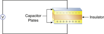
FIGURE 31-1 A capacitor consists of two parallel conductors separated by an insulator. The capacitor is capable of storing charge supplied by a voltage source (V).
In contrast to DC circuits, a capacitor in an AC circuit permits current flow even when the circuit is not completed by a resistance. This is because of the nature of AC circuits, in which the current flow is constantly being reversed. Because current flow results from the movement of electrons, the capacitor plates are alternately charged—first positive and then negative, with every reversal of the AC current direction—resulting in an effective current flow as far as the remainder of the circuit is concerned, even though the circuit is not completed.
Because the effect of capacitance on impedance varies directly with the AC frequency in hertz, the greater the AC frequency, the lower the impedance. Therefore, high-frequency currents (0.5 to 2 million Hz), such as those used by electrosurgical units (ESUs), will cause a marked decrease in impedance.
Electrical devices use capacitors for various beneficial purposes. However, a phenomenon known as stray capacitance is capacitance that was not designed into the system but is incidental to the construction of the equipment. All AC-operated equipment produces stray capacitance. An ordinary power cord, for example, that consists of two insulated wires running next to each other will generate significant capacitance simply by being plugged into a 120 V circuit, even though the piece of equipment is not turned on. Another example of stray capacitance is found in electric motors. The circuit wiring in electric motors generates stray capacitance to the metal housing of the motor. The clinical importance of capacitance will be emphasized later in the chapter.
Inductance
Whenever electrons flow in a wire, a magnetic field is induced around the wire. If the wire is coiled repeatedly around an iron core, as in a transformer, the magnetic field can be very strong. Inductance is a property of AC circuits in which an opposing EMF can be electromagnetically generated in the circuit. The net effect of inductance is to increase impedance. Because the effect of inductance on impedance also depends on AC frequency, increases in frequency will increase the total impedance. Therefore the total impedance of a coil will be much greater than its simple resistance.
Electrical Shock Hazards
Alternating and Direct Currents
Whenever an individual contacts an external source of electricity, an electric shock is possible. An electric current can stimulate skeletal muscle cells to contract and thus can be used therapeutically in devices such as pacemakers or defibrillators. However, casual contact with an electrical current, whether AC or DC, can lead to injury or death. Although it takes approximately three times as much DC as AC to cause ventricular fibrillation, this by no means renders DC harmless. Devices such as an automobile battery or a DC defibrillator can be sources of direct current shocks.
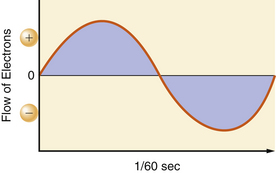
In the United States, utility companies supply energy in the form of alternating currents of 120 V at a frequency of 60 Hz. The 120 V of EMF and 1 A of current are the effective voltage and amperage in an AC circuit. This is also referred to as root-mean-square (RMS). It takes 1.414 A of peak amperage in the sinusoidal curve to give an effective amperage of 1 A. Similarly, it takes 170 V (120 × 1.414) at the peak of the AC curve to get an effective voltage of 120 V. The 60 Hz refers to the number of times in 1 second that the current reverses its direction of flow. Both the voltage and current waveforms form a sinusoidal pattern (Fig. 31-2).
To have the completed circuit necessary for current flow, a closed loop must exist, and a voltage source must drive the current through the impedance. If current is to flow in the electrical circuit, there has to be a voltage differential, or a drop in the driving pressure across the impedance. According to Ohm’s law, if the resistance is held constant, the greater the current flow, the larger the voltage drop must be.
The power company attempts to maintain the line voltage constant at 120 V. Therefore by Ohm’s law, the current flow is inversely proportional to the impedance. A typical power cord consists of two conductors: one, designated as hot, carries the current to the impedance; the other is neutral, and it returns the current to the source. The potential difference between the two is effectively 120 V (Fig. 31-3). The amount of current flowing through a given device is frequently referred to as the load. The load of the circuit depends on the impedance. A very high impedance circuit allows only a small current to flow and thus has a small load. A very low impedance circuit will draw a large current and is said to carry a large load. A short circuit occurs when there is a zero impedance load with a very high current flow.1
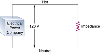
FIGURE 31-3 A typical alternating current (AC) circuit. A potential difference of 120 V exists between the hot and neutral sides of the circuit. The current flows through a resistance, which in AC circuits is more accurately referred to as impedance, and then returns to the electrical power company.
Source of Shocks
Electrical accidents or shocks occur when a person becomes part of, or completes, an electrical circuit. To receive a shock, a person must contact the electrical circuit at two points, and there must be a voltage source that causes the current to flow through the individual (Fig. 31-4).
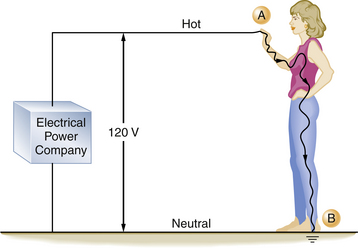
FIGURE 31-4 An individual can complete an electrical circuit and receive a shock. If the person is standing on the ground (point B), by coming in contact with the hot side of the circuit (point A), the contact point and the ground provide the two contact points necessary for a completed circuit. The severity of the shock received depends on the individual’s skin resistance.
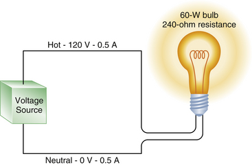
FIGURE 31-5 A 60 W lightbulb has an internal resistance of 240 Ω and draws a 0.5 A current. The voltage drop in the circuit is from 120 V in the hot wire to zero in the neutral wire, but the current is 0.5 A in both the hot and neutral wires.
When an individual comes in contact with a source of electricity, injury occurs in one of two ways. First, the electrical current can disrupt the normal electrical function of cells. Depending on its magnitude, the current can contract muscles, alter brain function, paralyze respiration, or disrupt normal heart function, leading to ventricular fibrillation. The second mechanism involves the dissipation of electrical energy throughout the body’s tissues. An electrical current passing through any resistant substance raises the temperature of that substance. If enough thermal energy is released, the temperature will rise sufficiently to produce a burn. Accidents involving household currents usually do not result in severe burns. However, in accidents involving very high voltages (i.e., power transmission lines), severe burns are common.
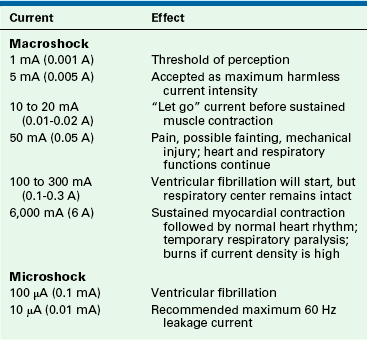
The severity of an electrical shock is determined by the amount of current (amperes) and the duration of the current flow. For the purposes of this discussion, electrical shocks are divided into two categories: macroshock refers to large amounts of current flowing through a person, which can cause harm or death; microshock refers to very small amounts of current. Concern for injury with microshock applies only to the electrically susceptible patient, an individual who has an external conduit that is in direct contact with the heart; this can be a pacing wire or a saline-filled catheter, such as a central venous or pulmonary artery catheter. In the case of the electrically susceptible patient, even minute amounts of current (microshocks) can cause ventricular fibrillation.
Table 31-1 shows the effects typically produced by various currents following a 1-second contact with a 60 Hz current. When an individual contacts a 120-V household current, the severity of the shock will depend on his or her skin resistance, the duration of the contact, and the current density. Skin resistance can vary from a few thousand to 1 million Ω. If a person with a skin resistance of 1000 Ω contacts a 120 V circuit, he or she would receive 120 mA of current, which would probably be lethal. However, if that same person’s skin resistance is 100,000 Ω, the current flow would be 1.2 mA, which would barely be perceptible.


The longer an individual is in contact with the electrical source, the more dire the consequences because more energy will be released, and more tissue will be damaged. Also, there will be a greater chance of ventricular fibrillation from excitation of the heart during the vulnerable period of the electrocardiogram (ECG) cycle.
Current density is a way of expressing the amount of current applied per unit area of tissue. The diffusion of current in the body tends to be in all directions. The greater the current or the smaller the area to which it is applied, the higher the current density. In relation to the heart, a current of 100 mA (100,000 μA) is generally required to produce ventricular fibrillation when applied to the surface of the body. However, only 100 μA (0.1 mA) is required to produce ventricular fibrillation when that minute current is applied directly to the myocardium through an instrument with a very small contact area, such as a pacing wire electrode. In this case, the current density is a thousandfold greater when applied directly to the heart; therefore only  of the energy is required to cause ventricular fibrillation. An electrically susceptible patient can be electrocuted with currents well below 1 mA, which is the threshold of perception for humans.
The frequency at which the current reverses is also an important factor in determining the amount of current an individual can safely contact. Utility companies in the United States produce electricity at a frequency of 60 Hz, because higher frequencies cause greater power loss through transmission lines, and lower frequencies cause a detectable flicker from light sources.2 The “let go” current is defined as that current above which sustained muscular contraction occurs and at which an individual would be unable to let go of an energized wire. The let-go current for 60 Hz AC power is 10 to 20 mA,1,3,4 whereas at a frequency of 1 million Hz, up to 3 A (3000 mA) is generally considered safe. It should be noted that very high frequency currents do not excite contractile tissue; consequently, they do not cause cardiac dysrhythmias.
It can be seen that Ohm’s law governs the flow of electricity. For a completed circuit to exist, a closed loop must exist with a driving pressure to force a current through a resistance, just as in the cardiovascular system, in which BP must drive the cardiac output through the peripheral resistance. Figure 31-5 illustrates that a hot wire carrying a 120 V pressure through the resistance of a 60 W lightbulb produces a current flow of 0.5 A. The voltage in the neutral wire is approximately zero volts, whereas the current in the neutral wire remains at 0.5 A. This correlates with our cardiovascular analogy, in which a mean BP decrease of 80 mm Hg between the aortic root and the right atrium forces a cardiac output of 6 L/min through a systemic vascular resistance of 13.3 resistance units. However, the flow—in this case, the cardiac output, or in the case of the electrical model, the current—is still the same everywhere in the circuit. That is, the cardiac output on the arterial side is the same as the cardiac output on the venous side.
Grounding
To fully understand electrical shock hazards and their prevention, the clinician must have a thorough knowledge of the concepts of grounding. These concepts of grounding probably constitute the most confusing aspects of electrical safety, because the same term is used to describe several different principles. In electrical terminology, the term grounding is applied to two separate concepts. The first is the grounding of electrical power, and the second is the grounding of electrical equipment. Thus the concepts that power can be grounded or ungrounded and that power can supply electrical devices that are themselves grounded or ungrounded are not mutually exclusive. It is vital to understand this point as the basis of electrical safety. Whereas electrical power is grounded in the home, it is usually ungrounded in the OR (Table 31-2). In the home, electrical equipment may be grounded or ungrounded, but it should always be grounded in the OR.

Electrical Power: Grounded
Electrical utilities universally provide power that is grounded (by convention, the earth-ground potential is zero, and all voltages represent a difference between potentials); that is, one of the wires supplying the power to a home is intentionally connected to the earth. The utility companies do this as a safety measure to prevent electrical charges from building up in their wiring during electrical storms. This also prevents the very high voltages used in transmitting power by the utility from entering the home in the event of an equipment failure in their high-voltage system.
The power enters the typical home via two wires attached to the main fuse box or circuit breaker box at the service entrance. The “hot” (electrified) wire supplies power to the hot distribution strip. The neutral wire is connected to the neutral distribution strip and to a service entrance ground (i.e., a pipe buried in the earth; Fig. 31-6). From the fuse box, three wires leave to supply the electrical outlets in the house. In the United States, the hot wire is color-coded black and carries a 120 V above-ground potential. The second wire is the neutral wire color-coded white; the third wire is the ground wire, which is either color-coded green or is uninsulated (bare wire). The ground and the neutral wires are attached at the same point in the circuit breaker box and are also connected to a cold-water pipe (Figs. 31-7 and 31-8). Thus, this grounded power system is also referred to as a neutral grounded power system. The black wire is not connected to the ground, because this would create a short circuit. The black wire is attached to the hot distribution strip (i.e., 120 V above ground) on which the circuit breakers or fuses are located. From here, numerous branch circuits supply electrical power to the outlets in the house. Each branch circuit is protected by a circuit breaker or fuse that limits current to a specific maximum amperage. Most electrical circuits in the house are 15 or 20 A circuits. These typically supply power to the electrical outlets and lights in the house. Several higher amperage circuits are also provided for certain devices, such as electric stoves or clothes dryers. These devices are powered by 240 V circuits, which can draw from 30 to 50 A of current. The circuit breaker or fuse will interrupt the flow of current on the hot side of the line in the event of a short circuit, or if the demand placed on that circuit is too high. For example, a 15 A branch circuit is capable of supporting 1800 W of power.
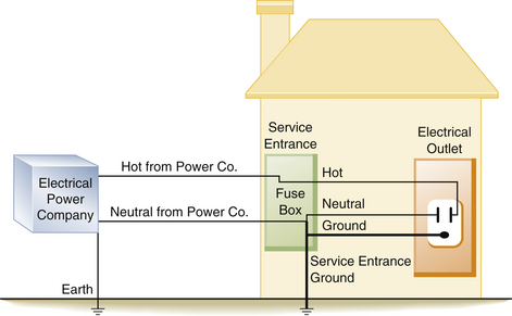
FIGURE 31-6 In a neutral grounded power system, the electric company supplies two lines to the typical home. The neutral wire is connected to ground by the power company and is also connected to a service entrance ground when it enters the fuse box or breaker panel. Both the neutral and ground wires are connected together in the supply box at the neutral bus bar, which is also attached to the service entrance ground.
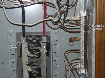
FIGURE 31-7 Inside a breaker panel with the circuit breakers removed. The arrowheads indicate the hot wires energizing the strips where the circuit breakers are located. The arrows point to the neutral bus bar, where the neutral and ground wires are connected.


Therefore if two 1500 W hair dryers were simultaneously plugged into one outlet, the load would be too great for a 15 A circuit, and the circuit breaker would open (trip), or the fuse would melt. This is designed to prevent the supply wires in the circuit from melting and starting a fire. The amperage of the circuit breaker on the branch circuit is determined by the thickness of the wire that it supplies. If a 20 A breaker is used with wire rated for only 15 A, the wire could melt and start a fire before the circuit breaker would trip. It is important to note that a 15 A circuit breaker does not protect an individual from lethal shocks; the 15 A of current that would trip the circuit breaker far exceeds the 100 to 200 mA that will produce ventricular fibrillation.
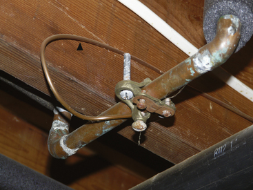
The wires that leave the circuit breaker supply the electrical outlets and lighting for the rest of the house. In older homes the electrical cable consists of two wires, a hot and a neutral, which supply power to the electrical outlets (Fig. 31-9). In newer homes, a third wire has been added to the electrical cable (Fig. 31-10). This third wire is either green or uninsulated (bare) and serves as a ground wire for the power receptacle (Fig. 31-11). On one end, the ground wire is attached to the receptacle (Fig. 31-12); on the other, it is connected to the neutral distribution strip in the circuit breaker box along with the neutral (white) wires (Fig. 31-13).
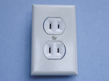
FIGURE 31-9 An older style electrical outlet. Only two wires are present, a hot and a neutral. There is no ground wire.
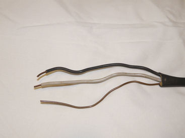
FIGURE 31-10 Modern electrical cable in which a third wire, or ground, has been added. Wires from top to bottom are hot, neutral, and ground.
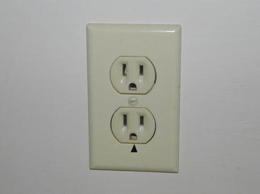
FIGURE 31-11 Modern electrical outlet in which the ground wire is present. The arrowhead points to the part of the receptacle where the ground wire connects.
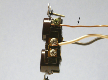
FIGURE 31-12 Detail of modern electrical power receptacle. The arrow points to the ground wire (bare wire), which is attached to the green grounding screw on the power receptacle.
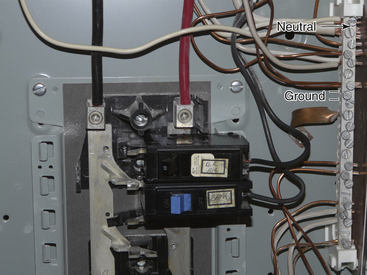
FIGURE 31-13 The ground wires (bare wires) from the power outlet are run to the neutral bus bar, where they are connected with the neutral wires (white wires; arrow).
It should be realized that in both the old and new situations, the power is grounded. That is, a 120 V potential exists between the hot (black) and the neutral (white) wire and between the hot wire and the ground. In this case, the ground is the earth (Fig. 31-14). In modern home construction, a 120 V potential difference exists between the hot and the neutral wire, and a difference of 120 V is found between the equipment ground wire, which is the third wire, and also between the hot wire and the earth (Fig. 31-15).
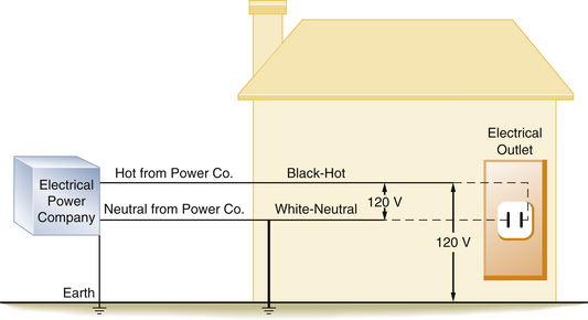
FIGURE 31-14 Diagram of a house with older style wiring that does not contain a ground wire. A 120 V potential difference exists between the hot and the neutral wires and between the hot wire and the earth.
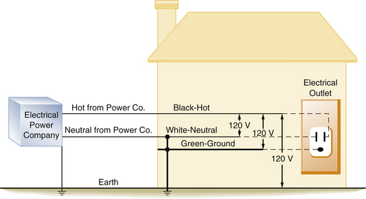
FIGURE 31-15 Diagram of a house with modern wiring in which a third wire, or ground, has been added. The 120 V potential difference exists between the hot and neutral wires, the hot and the ground wires, and the hot wire and the earth.
A 60 W lightbulb can be used as an example to further illustrate this point. Normally, the hot and neutral wires are connected to the two wires of the lightbulb socket, and throwing the switch will illuminate the bulb (Fig. 31-16). Similarly, if the hot wire is connected to one side of the bulb socket, and the other wire from the lightbulb is connected to the equipment ground wire, the bulb will still illuminate. If there is no equipment ground wire, the bulb will still light if the second wire is connected to any grounded metallic object, such as a water pipe or a faucet. This illustrates the fact that the 120 V potential difference exists not only between the hot and the neutral wires but also between the hot wire and any grounded object. Thus in a grounded power system, the current will flow between the hot wire and any conductor with an earth ground.
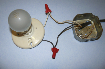
FIGURE 31-16 A simple lightbulb circuit. The hot (black) and neutral (white) wires are connected with the corresponding wires from the lightbulb fixture.
As previously stated, current flow requires a closed loop with a source of voltage. For an individual to receive an electric shock, he or she must contact the loop at two points. Because we may be standing either on the ground or in contact with an object that is referenced to the ground, only one additional contact point is necessary to complete the circuit and thereby receive an electrical shock. This is an unfortunate and inherently dangerous consequence of grounded power systems. Modern wiring systems have added the third wire, the equipment ground wire, as a safety measure to reduce the severity of a potential electrical shock. This is accomplished by providing an alternate, low-resistance pathway through which the current can flow to the ground.
Over time the insulation covering the wires may deteriorate. It is then possible for a bare, hot wire to contact the metal case or frame of an electrical device. The case would then become energized and would create a shock hazard to anyone coming in contact with it. Figure 31-17 illustrates a typical short circuit, in which the individual has come in contact with the hot (electrified) case of an instrument. This illustrates the type of wiring found in older homes: there is no ground wire in the electrical outlet, nor is the electrical apparatus equipped with a ground wire. Here, the individual completes the circuit and receives a severe shock. Figure 31-18 illustrates a similar example, except that now the equipment ground wire is part of the electrical distribution system. In this example, the equipment ground wire provides a pathway of low impedance through which the current can travel; therefore most of the current would travel through the ground wire. In this case, the person may get a shock, but it is unlikely to be fatal.
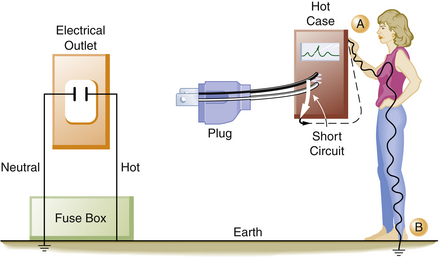
FIGURE 31-17 When a faulty piece of equipment without an equipment ground wire is plugged into an electrical outlet that also does not contain a ground wire, the case of the instrument will become hot. An individual touching the hot case (point A) will receive a shock because he or she is standing on the earth (point B), completing the circuit. The current (dashed line) will flow from the instrument through the individual touching the hot case.
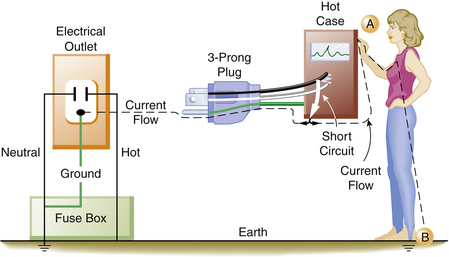
FIGURE 31-18 When a faulty piece of equipment with an equipment ground wire is properly connected to an electrical outlet with a grounding connection, the current (dashed line) will preferentially flow down the low-resistance ground wire. An individual touching the case (point A) while standing on the ground (point B) will still complete the circuit; however, only a small part of the current will go through the individual.
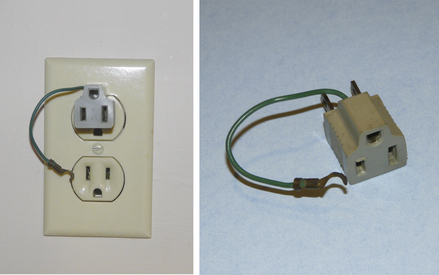
The electrical power supplied to homes is always grounded. A 120 V potential always exists between the hot conductor and the ground or earth. The third or equipment ground wire used in modern electrical wiring systems does not normally have current flowing through it. In the event of a short circuit, an electrical device with a three-prong plug (i.e., a ground wire connected to its case) will conduct the majority of the short-circuited or “fault” current through the ground wire and away from the individual. This provides a significant safety benefit to someone accidentally contacting the defective device. If a large enough fault current exists, the ground wire also will provide a means to complete the short circuit back to the circuit breaker or fuse, and this will either melt the fuse or trip the circuit breaker. Thus, in a grounded power system, it is possible to have either grounded or ungrounded equipment, depending on when the wiring was installed and whether the electrical device is equipped with a three-prong plug that contains a ground wire. Obviously, attempts to bypass the safety system of the equipment ground should be avoided. Devices such as a “cheater plug” (Fig. 31-19) should never be used because they defeat the safety feature of the equipment ground wire.
Electrical Power: Ungrounded
Numerous electronic devices, together with power cords and puddles of saline solution on the floor, make the OR an electrically hazardous environment for both patients and personnel. Bruner and colleagues5 found that 40% of electrical accidents in hospitals occurred in the OR. The complexity of electrical equipment in the modern OR demands that electrical safety be a factor of paramount importance. To provide an extra measure of safety from macroshock, the power supplied to most ORs is ungrounded. In this ungrounded power system, the current is isolated from ground potential. The 120 V potential difference exists only between the two wires of the isolated power system (IPS), but no circuit exists between the ground and either of the isolated power lines.
Supplying ungrounded power to the OR requires the use of an isolation transformer (Fig. 31-20). This device uses electromagnetic induction to induce a current in the ungrounded or secondary winding of the transformer from energy supplied to the primary winding. No direct electrical connection exists between the power supplied by the utility company on the primary side and the power induced by the transformer on the ungrounded, or secondary, side. Thus, the power supplied to the OR is isolated from ground (Fig. 31-21). Because the 120 V potential exists only between the two wires of the isolated circuit, neither wire is hot or neutral with reference to ground; in this case, they are simply referred to as line 1 and line 2 (Fig. 31-22). Using the example of the lightbulb, if the two wires of the bulb socket are connected to the two wires of the IPS, the bulb will illuminate. However, if one of the wires is connected to one side of the isolated power, and the other wire is connected to the ground, the light will not illuminate. If the wires of the IPS are connected, the short circuit will trip the circuit breaker. In comparing the two systems, standard grounded power has a direct connection to ground, whereas the isolated system imposes a very high impedance to any current flow to ground. The added safety of this system can be seen in Figure 31-23. In this case, a person has come in contact with one side of the IPS (point A). Because standing on the ground (point B) does not constitute a part of the isolated circuit, the individual does not complete the loop and will not receive a shock. This is because the ground is part of the primary circuit, and the person is contacting only one side of the isolated secondary circuit. The person does not complete either circuit; that is, the person does not have two contact points; therefore this situation does not pose an electric shock hazard. Of course, if the person contacts both lines of the IPS, an unlikely event, he or she would receive a shock.
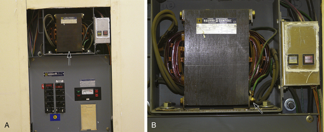
FIGURE 31-20 A, Isolated power panel showing circuit breakers, line isolation monitor, and isolation transformer (arrow). B, Detail of an isolation transformer with the attached warning lights. The arrow points to ground wire connection on the primary side of the transformer. Note that no similar connection exists on the secondary side of the transformer.
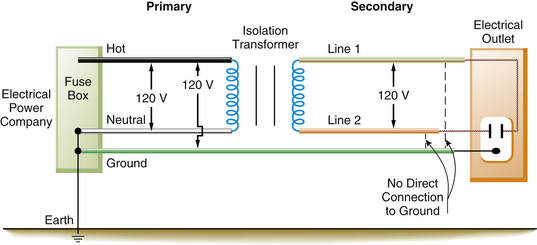
FIGURE 31-21 In the operating room, the isolation transformer converts the grounded power on the primary side to an ungrounded power system on the secondary side of the transformer. A 120 V potential difference exists between line 1 and line 2. There is no direct connection from the power on the secondary side to ground. The equipment ground wire, however, is still present.
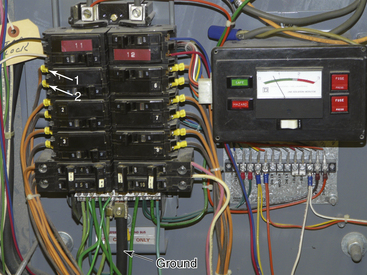
FIGURE 31-22 Detail of the inside of a circuit breaker box in an isolated power system. The bottom arrow points to ground (green) wires meeting at the common ground terminal. Arrows 1 and 2 indicate lines 1 and 2 (orange and brown) from the isolated power circuit breaker. Neither line 1 nor line 2 is connected to the same terminals as the ground wires. This is in marked contrast to Figure 31-13, where the neutral and ground wires are attached at the same point.

FIGURE 31-23 A safety feature of the isolated power system (IPS). An individual in contact with one side of the IPS (point A) and standing on the ground (point B) will not receive a shock. In this instance, the individual is not contacting the circuit at two points and thus is not completing the circuit. Point A is part of the IPS, and point B is part of the primary or grounded side of the circuit.
If a faulty electrical appliance with an intact equipment ground wire is plugged into a standard household outlet, and the home wiring has a properly connected ground wire, the amount of electrical current that will flow through a person is considerably less than what will flow through the low-resistance ground wire. Here, an individual would be fairly well protected from a serious shock. However, if that ground wire were broken, the person might receive a lethal shock. No shock would occur if the same faulty piece of equipment were plugged into the IPS, even if the equipment ground wire were broken. Thus the IPS provides a significant amount of protection from macroshock. Another feature of the IPS is that the faulty piece of equipment, even though it may be partially short-circuited, will not usually trip the circuit breaker. This is an important feature, because the faulty piece of equipment may be part of a life-support system for a patient. It is important to note that even though the power is isolated from ground, the case or frame of all electrical equipment is still connected to an equipment ground. The third wire, the equipment ground wire, is a necessary component of any electrical safety program.
Figure 31-24 illustrates a scenario involving a faulty piece of equipment connected to the IPS. This does not represent a hazard; it merely converts the isolated power back to a grounded power system as exists outside the OR. In fact, a second fault is necessary to create a hazard.
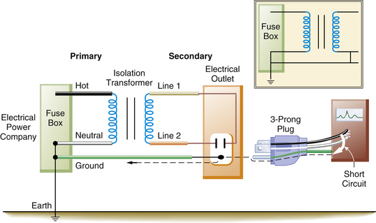
FIGURE 31-24 A faulty piece of equipment plugged into the isolated power system (IPS) does not present a shock hazard. It merely converts the IPS into a grounded power system. The inset illustrates that the IPS is now identical to the grounded power system. The dashed line indicates current flow in the ground wire.
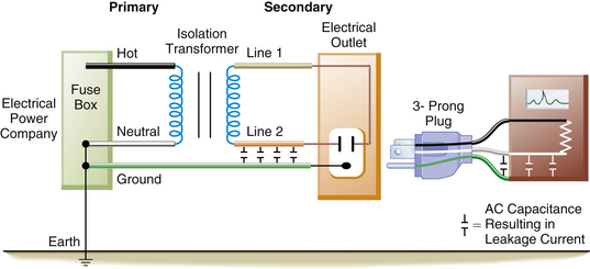
The previous discussion assumes that the IPS is perfectly isolated from ground. Actually, perfect isolation is impossible to achieve; all AC-operated power systems and electrical devices manifest some degree of capacitance. As previously discussed, electrical power cords, wires, and electrical motors exhibit capacitive coupling to the ground wire and metal conduits, and they leak small amounts of current to ground (Fig. 31-25). This so-called leakage current partially ungrounds the IPS; this does not usually amount to more than a few milliamperes in an OR, so a person coming in contact with one side of the IPS would receive only a very small shock (1 to 2 mA). Although this amount of current would be perceptible, it would not be dangerous.
Line Isolation Monitor
The line isolation monitor (LIM) is a device that continuously monitors the integrity of an IPS. If a faulty piece of equipment is connected to the IPS, this will, in effect, change the system back to a conventional grounded system. Also, the faulty piece of equipment will continue to function normally. Therefore it is essential that a warning system be in place to alert personnel that the power is no longer ungrounded. The LIM continuously monitors the isolated power to ensure that it is indeed isolated from ground, and the device has a meter that displays a continuous indication of the integrity of the system (Fig. 31-26). The LIM is actually measuring the impedance to ground of each side of the IPS. As previously discussed, with perfect isolation, impedance would be infinitely high, and no current would flow in the event of a first-fault situation (Z = E/I; if I = 0, then Z = ∞). Because all AC wiring and all AC-operated electrical devices have some capacitance, small leakage currents are present that partially degrade the isolation of the system. The meter of the LIM will indicate (in milliamperes) the total amount of leakage in the system resulting from capacitance, electrical wiring, and any devices plugged into the IPS.
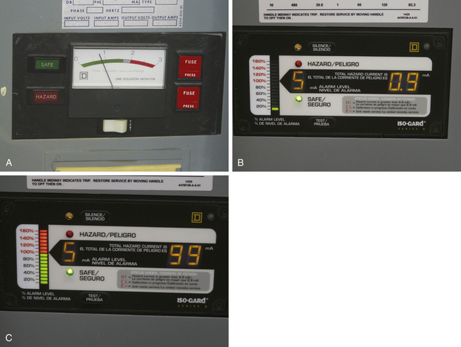
FIGURE 31-26 The meter of the line isolation monitor (LIM) is calibrated in milliamperes. If the isolation of the power system is degraded such that more than 2 mA of current (5 mA in newer systems) could flow, the hazard light will illuminate, and a warning buzzer will sound. Note the button for testing the hazard warning system. A, Older LIM that will trigger an alarm at 2 mA. B, Newer LIM that will trigger an alarm at 5 mA. C, The LIM alarm is triggered, and the red hazard stripe is illuminated; the number on the right shows 9.9 mA of potential current flow.
The reading on the LIM does not mean that current is actually flowing; rather it indicates how much current would flow in the event of a first fault. The LIM is set to alarm at 2 or 5 mA, depending on the age and brand of the system. Once this preset limit is exceeded, visual and audible alarms are triggered to indicate that the isolation from ground has been degraded beyond a predetermined limit (Fig. 31-27). This does not necessarily mean that a hazardous situation exists; rather it shows that the system is no longer totally isolated from ground; a second fault is required to create a dangerous situation. For example, if the LIM were set to alarm at 2 mA, using Ohm’s law, the impedance for either side of the IPS would be 60,000 Ω:
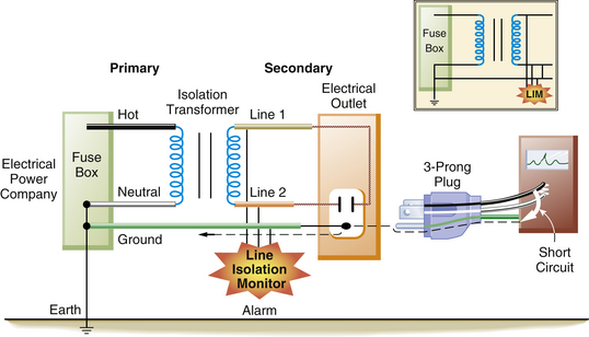
FIGURE 31-27 When a faulty piece of equipment is plugged into the isolated power system, it will markedly decrease the impedance from line 1 or line 2 to ground. This will be detected by the line isolation monitor, which will sound an alarm.


Therefore if either side of the IPS had less than 60,000 Ω impedance to ground, the LIM would trigger an alarm. This might occur in two situations. In the first, a faulty piece of equipment is plugged into the IPS. In this case, a true fault to ground exists from one line to the ground. Now the system would be converted to the equivalent of a grounded power system. This faulty piece of equipment should be removed and serviced as soon as possible, although it could still be used safely if it were essential for the care of the patient. It should be remembered, however, that continuing to use this faulty piece of equipment would create the potential for a serious electrical shock. This would occur if a second faulty piece of equipment were simultaneously connected to the IPS.
The second situation involves connecting many perfectly normal pieces of equipment to the IPS. Although each piece of equipment has only a small amount of leakage current, if the total leakage exceeds 2 mA, the LIM will trigger an alarm. Assume that 30 electrical devices are present in the OR, and each has 100 μA of leakage current; the total (30 × 100 μA) would be 3 mA. The impedance to ground would still be 40,000 Ω (120/0.003), and the LIM alarm would sound in this instance, because the 2 mA set point was violated. However, the system is still safe and represents a state significantly different from that in the first situation. For this reason, the newer LIMs are set to alarm at 5 mA instead of 2 mA.
The newest LIMs are referred to as third-generation monitors. The first-generation monitor, or static LIM, was unable to detect balanced faults (i.e., a situation in which there are equal faults to ground from both lines 1 and 2). The second-generation monitor, or dynamic LIM, did not have this problem but could interfere with physiologic monitoring. Both of these monitors would trigger an alarm at 2 mA, which led to annoying “false” alarms. The third-generation LIM corrects the problems of its predecessors and has the alarm threshold set at 5 mA.6 Proper functioning of the LIM depends on having both equipment ground wires intact and its own connection to ground. First- and second-generation LIMs could not detect the loss of the LIM ground connection. The third-generation LIM can detect this loss of ground to the monitor. In this case, the LIM alarm would sound, and the red hazard light would illuminate, but the LIM meter would read zero; this condition will alert the staff that the LIM needs to be repaired. In any event, the LIM still cannot detect broken equipment ground wires. An example of the third-generation LIM is the Iso-Gard, made by Square D (Monroe, NC).
The equipment ground wire is again an important part of the safety system. If this wire is broken, a faulty piece of equipment plugged into an outlet would operate normally, but the LIM would not alarm. A second fault could therefore cause a shock without any alarm from the LIM. Also, in the event of a second fault, the equipment ground wire provides a low-resistance path to ground for most of the fault current (see Fig. 31-24). The LIM will only be able to register leakage currents from pieces of equipment that are connected to the IPS and that have intact ground wires.
If the LIM alarm is triggered, the first thing to do is to check the gauge to determine whether it is a true fault; the other possibility is that too many pieces of electrical equipment have been plugged in, and the 2 mA limit has been exceeded. If the gauge is between 2 and 5 mA, it is probable that too much electrical equipment has been plugged in. If the gauge reads over 5 mA, most likely a faulty piece of equipment is present. The next step is to identify the faulty equipment, which is done by unplugging each piece of equipment until the alarm ceases. If the faulty piece of equipment is not of a critical nature, it should be removed from the OR. If it is a vital piece of life-support equipment, it can be safely used. (Note: if a critical piece of life-support equipment, such as the cardiopulmonary bypass machine, is the suspected cause of the alarm, do not disconnect it until it is no longer needed.) It must be remembered that the protection of the IPS and the LIM is no longer operative. Therefore if possible, no other electrical equipment should be connected during the remainder of the case, or at least until the faulty piece of equipment can be safely removed.
Ground Fault Circuit Interrupter
The ground fault circuit interrupter (GFCI, or occasionally GFI) is another popular device used to prevent individuals from receiving an electrical shock in a grounded power system. Electrical codes for most new construction require that a GFCI circuit be present in potentially hazardous (e.g., wet) areas such as bathrooms, kitchens, or outdoors. The GFCI may be installed as an individual power outlet (Fig. 31-28), or a special circuit breaker may be installed to which all the individual protected outlets are connected at a single point. The special GFCI circuit breaker is located in the main breaker box and can be distinguished by its red test button (Fig. 31-29). As Figure 31-5 demonstrates, the current flowing in both the hot and neutral wires is usually equal. The GFCI monitors both sides of the circuit for the equality of current flow; if a difference is detected, the power is immediately interrupted. If an individual should contact a faulty piece of equipment such that current flowed through the person, an imbalance between the two sides of the circuit would be created, which would be detected by the GFCI. Because the GFCI can detect very small current differences (in the range of 5 mA), the GFCI will open the circuit within a few milliseconds, thereby interrupting the current flow before a significant shock occurs. Thus the GFCI provides a high level of protection at a very modest cost. If the OR has a GFCI that tripped, an attempt should first be made to reset it by pushing the reset button; this is because a surge may have caused the GFCI to trip. If it cannot be reset, the equipment must be removed from service and checked by the biomedical engineering staff. It is essential that when GFCIs are used in an OR, only one outlet should be protected by each GFCI. They should never be “daisy-chained” such that one GFCI protects multiple outlets.
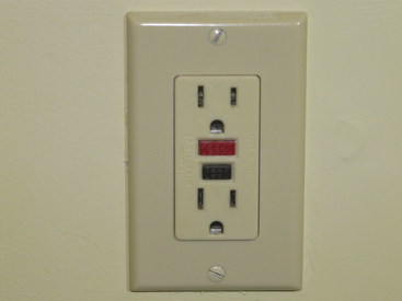
FIGURE 31-28 A ground fault circuit interrupter electrical outlet with integrated test (black) and reset (red) buttons.
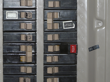
FIGURE 31-29 Special ground fault circuit interrupter circuit breaker. Note the distinguishing red test button.
The disadvantage of using a GFCI in the OR is that it interrupts the power without warning. A defective piece of equipment could no longer be used, which could be a problem if it were essential for life support; whereas if the same faulty piece of equipment were plugged into an IPS, the LIM would alarm, but the equipment could still be used.
Double Insulation
One instance in which it is acceptable for a piece of equipment to have only a two-prong and not a three-prong plug is when the instrument has what is termed double insulation. These instruments have two layers of insulation and usually have a plastic exterior. Double insulation is found in many home power tools and is seen in hospital equipment such as infusion pumps. Double-insulated equipment is permissible in the OR with IPSs; however, if water or saline should get inside the unit, it could present a hazard because the double insulation is bypassed. This is even more serious if the OR has no isolated power or GFCIs.7
Microshock
As previously discussed, macroshock involves relatively large amounts of current applied to the surface of the body. The current is conducted through all the tissues in proportion to their conductivity and area in a plane perpendicular to the current. Consequently, the “density” of the current (amperes per meter squared) that reaches the heart is considerably less than what is applied to the body surface. However, an electrically susceptible patient—one who has a direct external connection to the heart, such as through a central venous pressure catheter or transvenous cardiac pacing wires—may be at risk from very small currents; this is called microshock.8 The catheter orifice or electrical wire with a very small surface area in contact with the heart produces a relatively large current density at the heart.9 Stated another way, even very small amounts of current applied directly to the myocardium will cause ventricular fibrillation. Microshock is a particularly difficult problem because of the insidious nature of the hazard.
In the electrically susceptible patient, ventricular fibrillation can be produced by a current that is below the threshold of human perception. The exact amount of current necessary to cause ventricular fibrillation in this type of patient is unknown. Whalen and colleagues10 were able to produce fibrillation with 20 μA of current applied directly to the myocardium of dogs. Raftery and colleagues11 produced fibrillation with 80 μA of current in some patients. Hull12 used data obtained by Watson and collagues13 to show that 50% of patients would fibrillate at currents of 200 μA. Because 1000 μA (1 mA) is generally regarded as the threshold of human perception with 60 Hz AC, the electrically susceptible patient can be electrocuted with one tenth of the normally perceptible currents. This is not only of academic interest but also of practical concern, because many cases of ventricular fibrillation from microshock have been reported.14-18
The stray capacitance that is part of any AC-powered electrical instrument may result in significant amounts of charge buildup on the case of the instrument. If an individual simultaneously touches the case of an instrument where this has occurred in the electrically susceptible patient, he or she may unknowingly cause a discharge to the patient that results in ventricular fibrillation. Once again, the equipment ground wire constitutes the major source of protection against microshock for the electrically susceptible patient. In this case, the equipment ground wire provides a low-resistance path by which most of the leakage current is dissipated instead of stored as a charge.
Figure 31-30 illustrates a situation involving a patient with a saline-filled catheter in the heart with a resistance of about 500 Ω. The ground wire with a resistance of 1 Ω is connected to the instrument case, and a leakage current of 100 μA will divide according to the relative resistances of the two paths: in this case, 99.8 μA will flow through the equipment ground wire, and only 0.2 μA will flow through the fluid-filled catheter. This extremely small current does not endanger the patient. However, if the equipment ground wire were broken, the electrically susceptible patient would be at great risk, because all 100 μA of leakage current could flow through the catheter and cause ventricular fibrillation (Fig. 31-31). Currently, electronic equipment is permitted 100 μA of leakage current.
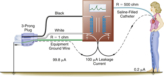
FIGURE 31-30 The electrically susceptible patient is protected from microshock by the presence of an intact equipment ground wire. The equipment ground wire provides a low-impedance path in which the majority of the leakage current (dashed lines) can flow. R, resistance.
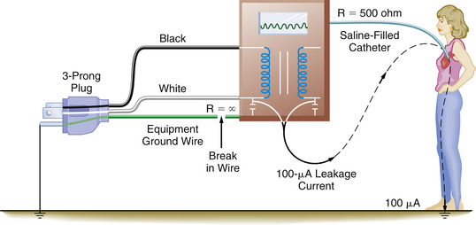
FIGURE 31-31 A broken equipment ground wire results in a significant hazard to the electrically susceptible patient. In this case, the entire leakage current can be conducted to the heart and may result in ventricular fibrillation. R, resistance.
Modern patient monitors incorporate another mechanism to reduce the risk of microshock for electrically susceptible patients.19 This mechanism involves electrically isolating all direct patient connections from the power supply of the monitor by placing a very high impedance between the patient and any device. This limits the amount of internal leakage through the patient connection to a very small value; the standard currently is less than 10 μA. For instance, the output of an ECG monitor’s power supply is electrically isolated from the patient by placing a very high impedance between the monitor and the patient’s ECG leads.20 Isolation techniques are designed to inhibit hazardous electrical pathways between the patient and the monitor while allowing the passage of the physiologic signal.
An intact equipment ground wire is probably the most important factor in preventing microshock. There are, however, other things that the anesthesiologist can do to reduce the incidence of microshock, such as to never simultaneously touch an electrical device and a saline-filled central catheter or external pacing wires. When handling a central catheter or pacing wires, it is best to insulate oneself by wearing rubber gloves. Also, never let any external current source, such as a nerve stimulator, come into contact with the catheter or wires. Finally, be alert to potential sources of energy that can be transmitted to the patient; even stray radiofrequency current from the ESU (cautery) can, under the right conditions, be a source of microshock.21 It must be remembered that the LIM is not designed to provide protection from microshock. The microampere currents involved in microshock are far below the LIM threshold of protection. In addition, the LIM does not register the leakage of individual monitors but rather indicates the status of the total system. The LIM reading indicates the total amount of leakage current resulting from the entire capacitance of the system. This is the amount of current that would flow to ground in the event of a first-fault situation.
The essence of electrical safety is a thorough understanding of all the principles of grounding; the objective of preventing injury is to make it difficult for electrical current to pass through people. For this reason, both the patient and the anesthesiologist should be isolated from ground as much as possible. That is, their resistance to current flow should be as high as is technologically feasible.
In the inherently unsafe electrical environment of an OR, several measures can be taken to help protect against contacting hazardous current flows. First, the grounded power provided by the utility company can be converted to ungrounded power by means of an isolation transformer. The LIM will continuously monitor the status of this isolation from ground and will issue a warning when the isolation of the power (from ground) has been lost, in the event that a defective piece of equipment is plugged into one of the isolated circuit outlets. In addition, the shock that an individual could receive from a faulty piece of equipment is determined by the capacitance of the system and is limited to a few milliamperes. Because all equipment plugged into the IPS has an equipment ground wire attached to the case of the instrument, this equipment ground wire will provide an alternative low-resistance pathway to enable potentially dangerous currents to flow to ground. Thus the patient and the anesthesiologist should be as insulated from ground as much as possible, and all electrical equipment should be grounded.
The equipment ground wire serves three functions. First, it provides a low-resistance path for fault currents to reduce the risk of macroshock. Second, it dissipates leakage currents that are potentially harmful to the electrically susceptible patient. Third, it provides information to the LIM on the status of the ungrounded power system. If the equipment ground wire is broken, a significant factor in the prevention of electrical shock is lost. Additionally, the IPS will appear safer than it actually is, because the LIM is unable to detect broken equipment ground wires.
Because power cords, plugs, and receptacles are subjected to greater abuse in the hospital than in the home, the Underwriters Laboratories (Melville, NY) has issued a strict specification for special “hospital grade” plugs and receptacles (Fig. 31-32). The plugs and receptacles that conform to this specification are marked by a green dot.22 The hospital-grade plug is one that can be visually inspected or easily disassembled to ensure the integrity of the ground wire connection; molded opaque plugs are not acceptable. Edwards23 reported that of 3000 non–hospital-grade receptacles installed in a new hospital building, 1800 (60%) were found to be defective after 3 years. When 2000 of the non–hospital-grade receptacles were replaced with hospital-grade receptacles, no failures occurred after 18 months of use.
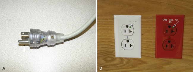
FIGURE 31-32 A, A hospital-grade plug that can be visually inspected. The arrow points to the equipment ground wire, whose integrity can be readily verified. Note that the prong for the ground wire (arrow) is longer than the hot or neutral prong, so that it is the first to enter the receptacle. B, The arrows point to the green dot, denoting a hospital-grade power outlet. The red outlet on the right is connected to the emergency power (generator) system.
Electrosurgery
On that fateful October day in 1926, when Dr. Harvey W. Cushing first used an electrosurgical (ESU) machine invented by Professor William T. Bovie to resect a brain tumor, the course of modern surgery and anesthesia was forever altered.24 The ubiquitous use of electrosurgery attests to the success of Professor Bovie’s invention. However, this technology was not adopted without a cost. The widespread use of electrocautery has, at the very least, hastened the elimination of explosive anesthetic agents from the OR. In addition, as every anesthesiologist is aware, few things in the OR are immune to interference from the “Bovie.” The high-frequency electrical energy generated by the ESU interferes with everything from the ECG signal to cardiac output computers, pulse oximeters, and even implanted cardiac pacemakers.25
The ESU operates by generating currents of a very high frequency—in the radiofrequency range, anywhere from 500,000 to 1 million Hz. Heat is generated whenever a current passes through a resistance, and the amount of heat produced (H) is proportional to the square of the current and inversely proportional to the area through which the current passes (H = I2/A).26 By concentrating the energy at the tip of the “Bovie pencil,” the surgeon can produce either a cut or a coagulation at any given spot. This very-high-frequency current behaves differently from the standard 60 Hz AC current and can pass directly across the precordium without causing ventricular fibrillation.26 This is because high-frequency currents have a low tissue penetration and do not excite contractile cells.
Although the ESU is used safely hundreds of thousands of times each year, there is evidence that under certain circumstances it has been the cause of ventricular fibrillation.27-30 The mechanism is thought to be low frequency (50 to 60 Hz) “stray current” generated when the ESU is activated. Current in the 50 to 60 Hz range can cause ventricular fibrillation. These cases have been associated with use of the coagulation mode, when the surgeon is using the device near the heart, and when the patient has a conductor in the heart such as a central venous pressure or pulmonary artery catheter. However, the exact mechanism has not been proven.
The large amount of energy generated by the ESU can pose other problems to the operator and the patient. Cushing became aware of one such problem. He wrote, “Once the operator received a shock which passed through a metal retractor to his arm and out by a wire from his headlight, which was unpleasant to say the least.”31 The ESU cannot be safely operated unless the energy is properly routed from the ESU through the patient and back to the unit. Ideally, the current generated by the active electrode is concentrated at the ESU tip, constituting a very small surface area. This energy has a high current density and is able to generate enough heat to produce a therapeutic cut or coagulation. The energy then passes through the patient to a dispersive electrode of large surface area that returns the energy safely to the ESU (Fig. 31-33).
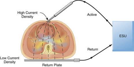
FIGURE 31-33 A properly applied electrosurgical unit (ESU) return plate. The current density at the return plate is low, resulting in no danger to the patient.
One unfortunate quirk in terminology concerns the return (dispersive) plate of the ESU. This plate, often incorrectly referred to as a ground plate, is actually a dispersive electrode of large surface area that safely returns the generated energy to the ESU via a low current density pathway. When inquiring whether the dispersive electrode has been attached to the patient, OR personnel frequently ask, “Is the patient grounded?” Because the aim of electrical safety is to isolate the patient from ground, this expression is worse than erroneous; it can lead to confusion. Because the area of the return plate is large, the current density is low; therefore, no harmful heat is generated, and no tissue destruction occurs. In a properly functioning system, the only tissue effect is at the site of the active electrode held by the surgeon.
Problems can arise if the electrosurgical return plate is improperly applied to the patient or if the cord connecting the return plate to the ESU is damaged or broken. In these instances, the high-frequency current generated by the ESU will seek an alternate return pathway. Anything attached to the patient, such as ECG leads or a temperature probe, can provide this alternate return pathway. The current density at the ECG pad will be considerably higher than normal, because its surface area is much less than that of the ESU return plate; this may result in a serious burn at this alternate return site. Similarly, a burn may occur at the site of the ESU return plate if it is not properly applied to the patient, or if it becomes partially dislodged during the operation (Fig. 31-34). This is not merely a theoretical possibility but is evidenced by the numerous case reports involving patients who have received ESU burns.32-37
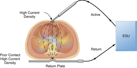
FIGURE 31-34 An improperly applied electrosurgical unit (ESU) return plate. Poor contact with the return plate results in a high current density and a possible burn to the patient.
The original ESUs were manufactured with the power supply connected directly to ground by the equipment ground wire. These devices made it extremely easy for ESU current to return by alternate pathways. The ESU would continue to operate normally even without the return plate connected to the patient. In most modern ESUs, the power supply is isolated from ground to protect the patient from burns.38 It was hoped that by isolating the return pathway from ground, the only route for current flow would be via the return electrode. Theoretically, this would eliminate alternate return pathways and greatly reduce the incidence of burns. However, Mitchell39 found two situations in which the current could return via alternate pathways, even with the isolated ESU circuit. If the return plate were left either on top of an uninsulated ESU cabinet or in contact with the bottom of the OR table, the ESU could operate fairly normally, and the current would return via alternate pathways. It should be recalled that the impedance is inversely proportional to the capacitance times the current frequency. The ESU operates at 500,000 to more than 1 million Hz, which greatly enhances the effect of capacitive coupling and causes a marked reduction in impedance. Therefore even with isolated ESUs, the decrease in impedance allows the current to return to the ESU by alternate pathways. In addition, the isolated ESU does not protect the patient from burns if the return electrode does not make proper contact with the patient. Although the isolated ESU does provide additional patient safety, it is by no means foolproof protection against the patient receiving a burn.
Preventing patient burns from the ESU is the responsibility of all professional staff in the OR. Not only the circulating nurse but also the surgeon and the anesthesiologist must be aware of proper techniques and be vigilant to potential problems. The most important factor is the proper application of the return plate; it is essential that the return plate has the appropriate amount of electrolyte gel and an intact return wire. Reusable return plates must be properly cleaned after each use, and disposable plates must be checked to ensure that the electrolyte has not dried out during storage. In addition, it is prudent to place the return plate as close as possible to the site of the operation; ECG pads should be placed as far from the site of the operation as is feasible. In addition, OR personnel must be alert to the potential for pools of flammable “prep” solutions, such as alcohol and acetone, to ignite when the ESU is used. If the ESU must be used on a patient with a demand pacemaker, the return electrode should be located below the thorax; in addition, preparations for treating potential dysrhythmias should be available, including a defibrillator, an external pacemaker, and a magnet to convert the pacemaker to a fixed rate. It is best to keep the pacemaker out of the path between the surgical site and the dispersal plate.
The ESU has also caused other problems in patients with pacemakers, including reprogramming and microshock.40,41 If the surgeon requests higher than normal power settings on the ESU, this should alert both the circulating nurse and the anesthesiologist to a potential problem. The return plate and cable must be immediately inspected to ensure that it is functioning and properly positioned. If this does not correct the problem, the return plate should be replaced.42,43 If the problem remains, the entire ESU should be taken out of service. Finally, an ESU that is dropped or damaged must be removed immediately from the OR and thoroughly tested by a qualified biomedical engineer. Following these simple safety steps will prevent most patient burns from the ESU.
The previous discussion concerned only unipolar ESUs; a second type of ESU, in which the current passes only between the two blades of a pair of forceps, is also used. This type of device is referred to as a bipolar ESU. Because the active and return electrodes are the two blades of the forceps, it is not necessary to attach another dispersive electrode to the patient, unless a unipolar ESU is also being used. The bipolar ESU generates considerably less power than the unipolar device and is mainly used for ophthalmic and neurologic surgery.
In 1980 Mirowski and colleagues44 reported the first human implantation of a device to treat intractable ventricular tachydysrhythmias. This device, known as the automatic implantable cardioverter-defibrillator (AICD), is capable of sensing ventricular tachycardia and ventricular fibrillation and automatically defibrillating the patient. Since 1980, thousands of patients have received AICD implants.45,46 Because some of these patients may come in for noncardiac surgery, it is important that the anesthesiologist be aware of potential problems.47 The use of a unipolar ESU may cause electrical interference that could be interpreted by the AICD as a ventricular tachydysrhythmia. This would trigger a defibrillation pulse to be delivered to the patient and would likely cause an actual episode of ventricular tachycardia or ventricular fibrillation. The patient with an AICD is also at risk for ventricular fibrillation during electroconvulsive therapy.47 In both cases, the AICD should be disabled by placing a magnet over the device or by use of a specific protocol to shut it off; the device can be reactivated by reversing the process. In any event, it is best to consult with someone experienced with the device before starting surgery. Also, an external defibrillator and a noninvasive pacemaker should be in the OR whenever a patient with an AICD is anesthetized.
Electrical safety in the OR is a matter of combining common sense with some basic principles of electricity. Once OR personnel understand the importance of safe electrical practices, they are able to develop a heightened awareness to potential problems. All electrical equipment must undergo routine maintenance, service, and inspection to ensure that it conforms to designated electrical safety standards. Records of these test results must be kept for future inspection, because human error can easily compound electrical hazards. Starmer and colleagues48 cited one case concerning a newly constructed laboratory, where the ground wire was not attached to a receptacle. In another study Albisser and colleagues49 found a 14% (198 of 1424) incidence of improperly or incorrectly wired outlets.
Potentially hazardous situations should be recognized and corrected before they become a problem. For instance, electrical power cords are frequently placed on the floor where they can be crushed by various carts or the anesthesia machine. These cords could be located overhead or placed in an area of low traffic flow. Multiple-plug extension boxes should not be left on the floor where they can come in contact with electrolyte solutions. These could easily be mounted on a cart or on the anesthesia machine. Pieces of equipment that have been damaged or have obvious defects in the power cord must not be used until they have been properly repaired. If everyone is aware of what constitutes a potential hazard, dangerous situations can be prevented with minimal effort.
Sparks generated by the ESU may provide the ignition source for a fire with resulting burns to the patient and OR personnel. This is a particular risk when the ESU is used in an oxygen-enriched environment as may be present in the patient’s airway or in close proximity to the patient’s face. The administration of high-flow nasal oxygen to a sedated patient during procedures on the face and eye is particularly hazardous. Most plastics that would not burn in room air, such as tracheal tubes and components of the anesthetic breathing system, will ignite in the presence of oxygen or nitrous oxide. Tenting of the drapes to allow dispersion of any accumulated oxygen or its dilution by room air or use of a circle anesthesia breathing system with minimal to no leak of gases around the anesthesia mask will decrease the risk of ignition from a spark generated by a nearby ESU.
Conductive Flooring
In the past, conductive flooring was mandated for ORs where flammable anesthetic agents were being administered to minimize the buildup of static charges that could cause a flammable anesthetic agent to ignite. The standards have now been changed to eliminate the necessity for conductive flooring in anesthetizing areas where flammable agents are no longer used.
Environmental Hazards
A number of potential electrical hazards in the OR are of concern to the anesthesiologist. The potential for electrical shock is present not only for the patient but also for OR personnel. In addition, cables and power cords to electrical equipment and monitoring devices can become hazardous through wear and misuse. Finally, all OR personnel should have a plan that outlines what to do in the event of a power failure.
Today’s OR is populated with literally dozens of pieces of electrical equipment. It is not uncommon to have numerous power cords lying on the floor, where they are vulnerable to damage. If the insulation on the power cable becomes damaged, it is fairly easy for the hot wire to come in contact with a piece of metal equipment. If the OR does not have isolated power, that piece of equipment can become energized and pose a potential electrical shock hazard.50 Having isolated power minimizes the risk to the patient and OR personnel. Clearly, getting electrical power cords off the floor is desirable. This can be accomplished by having electrical outlets in the ceiling or by having ceiling-mounted articulated arms that contain electrical outlets. Also, the use of multiple-outlet extension boxes that sit on the floor can be hazardous and should be avoided. In addition, these can become contaminated with fluids, which could easily trip the circuit breaker. In one case, it apparently tripped the main circuit breaker for the entire OR and resulted in a loss of all electrical power except for the overhead lights.51
Modern monitoring devices have many safety features incorporated into them. Virtually all of them have isolated the patient input from the power supply of the device. This is frequently done with optocoupler isolation circuits, an important feature that was lacking in the original ECG monitors. In the early days, patients could actually become part of the electrical circuit of the monitor. Relatively few problems have been experienced with patients and monitoring devices since the advent of isolated inputs. However, between 1985 and 1994, the Food and Drug Administration (FDA) received approximately 24 reports in which infants and children had received an electrical shock, including five children who died by electrocution.52,53 These electrical accidents occurred because the electrode lead wires from either an ECG monitor or an apnea monitor were plugged directly into a 120 V electrical outlet instead of the appropriate patient cable. In 1997, the FDA issued a new performance standard for electrode lead wires and patient cables that requires exposed male connector pins from the electrode lead wires to be eliminated. Therefore, the lead wires must have female connections, and the connector pins must be housed in a protected patient cable (Fig. 31-35). This effectively eliminates the possibility of the patient being connected directly to an AC source, because no connector pins on the lead wires are exposed.
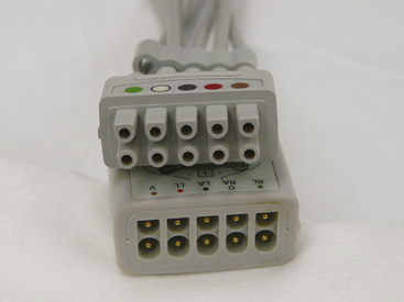
FIGURE 31-35 The current standard for patient lead wires (top) requires a female connector. The patient cable (bottom) has shielded connector pins that the lead wires plug into.
All health care facilities are required to have a source of emergency power. This generally consists of one or more electrical generators configured to start up automatically and provide power to the facility within 10 seconds after detecting a loss of power from the utility company. The facility is required to test these generators on a regular basis. However, in the past, not all health care facilities tested them under actual load. There are numerous anecdotal reports of generators not functioning properly during an actual power failure. If the generators are not tested under actual load, it is possible that many years will pass before a real power outage puts a severe demand on the generator. If the facility has several generators and one of them fails, the increased demand on the others may be enough to cause them all to fail in rapid succession. Under the current National Fire Protection Association (NFPA) 99 standards, hospitals must test their emergency power supply systems (generators) under connected load once a month for at least 30 minutes. If the generator is oversized for the application and cannot be loaded to at least 30% of its rating, it must be load-banked and run for a total of 2 hours every year. A fairly recent requirement is for emergency power supply systems to be tested once every 3 years for 4 continuous hours, with a recommendation that this be performed during peak usage of the system.54,55
Although all hospitals are required to have emergency generators to power essential equipment in the event of a power failure, they do not function in every circumstance. If there is a loss of power from the electrical utility, this is detected by a relay switch, which causes a series of events to activate the transfer of the power generation to the backup system. This usually happens seamlessly. However, if the transfer switch or the generator fails, there will be no back-up electricity.
Another cause of partial or total power failure has to do with construction mishaps. As hospitals frequently remodel, add new wings, or upgrade existing facilities, there is always a chance that the power will be accidentally interrupted, such as from a worker tripping a GFCI or a relay failure that causes a power transfer to a nonworking generator.56,57 Because the electrical utility is still supplying power, the generators may not be activated.
It is vitally important that each OR have a contingency plan for a power failure. There should be a supply of battery-operated light sources available in each OR. A laryngoscope can serve as a readily available source of light until flashlights and such can be located. The overhead lights in the OR should also be connected to some sort of battery-operated lighting system. Most anesthesia machines have a back-up battery that will last 30 to 60 minutes. If the power failure lasts longer than that, the anesthesiologist must plan how to continue the anesthetic. The newer electronic machines may be more problematic than older traditional machines, because they may have electronic gas or vaporization systems. The department should have a supply of battery-powered monitors, but it is unlikely there will be enough for every OR. Syringe pumps typically have a battery, and BP can be taken with a manual sphygmomanometer. Because many ORs use automated drug-dispensing systems, these devices will not work without power and a communication link to the hospital information system. In reality, the back-up generators will usually supply power in the event of an emergency. However, there are many circumstances in which a hospital could experience partial or total power loss. And although the cost of preparing for these contingencies is relatively small, the benefits can be invaluable in an emergency.
Electromagnetic Interference
Rapid advances in technology have led to an explosion in the number of wireless communication devices in the marketplace. These devices include cellular telephones, cordless telephones, walkie-talkies, and wireless Internet access devices. All of these devices have something in common: they emit electromagnetic interference (EMI). The problem with this most commonly manifests when traveling on airplanes: most airlines require that these devices be turned off when the plane is taking off or landing, and in some cases during the entire flight, because of a concern that the EMI emitted by these devices may interfere with the plane’s navigation and communication equipment.
In recent years, the number of people who own these devices has increased exponentially. Indeed, in some hospitals, such devices form a vital link in both the regular and emergency communication systems. It is not uncommon for physicians, nurses, paramedics, and other personnel to have their own cellular telephones. In addition, patients and visitors may also have cellular telephones and other types of communication devices. Hospital maintenance and security personnel frequently have walkie-talkie–type radios, and some hospitals have even instituted an in-house cellular telephone network that augments or replaces the paging system. However, concern has been raised that the EMI emitted by these devices may interfere with implanted pacemakers and various types of monitoring devices and ventilators in critical care areas.58 One patient death was reported when a ventilator malfunctioned secondary to EMI.59
Several studies have been done to find out whether cellular telephones cause problems with cardiac pacemakers. One report by Hayes and colleagues60 studied 980 patients with five different types of cellular telephones. They conducted more than 5000 tests and found that in more than 20% of the cases, they could detect some interference from the cellular telephone. Patients were symptomatic in 7.2% of the cases, and clinically significant interference occurred in 6.6% of the cases. When the telephone was held in the normal position over the ear, clinically significant interference was not detected. In fact, the interference that caused clinical symptoms occurred only if the telephone was directly over the pacemaker. Other studies have demonstrated changes such as erroneous sensing and pacer inhibition.61,62 Again, these occurred only when the telephone was close to the pacemaker. The changes were temporary, and the pacemaker reverted to normal when the cellular telephone was moved to a safe distance. Currently, the FDA guidelines are that the cellular telephones be kept at least 6 inches from the pacemaker. Therefore, a patient with a pacemaker should not carry a cellular telephone in a shirt pocket adjacent to the pacemaker. There appears to be little risk if hospital personnel carry a cellular telephone if they ensure that it is kept at a reasonable distance from patients with a pacemaker.
AICDs comprise another group of devices of concern to biomedical engineers. Fetter and colleagues63 conducted a study of 41 patients who had AICDs. They concluded that cellular telephones did not interfere with AICDs, although they did recommend keeping the cellular telephone at least 6 inches from the device.
EMI extends well beyond that of cellular telephones. Walkie-talkies, which are frequently used by hospital maintenance and security personnel; paging systems; police radios; and even televisions all emit EMI that could potentially interfere with medical devices. Although anecdotal reports abound, the amount of available scientific information on this problem is scant. Reports of interference include ventilator and infusion pumps that have been shut down or reprogrammed, interference with ECG monitors, and even an electronic wheelchair that was accidentally started because of EMI. It is a difficult problem to study because of the many different types of devices that emit EMI and the vast array of medical equipment with the potential to interact with these devices. Even though a device may seem safe in the medical environment, if two or three cellular telephones or walkie-talkies are brought together in the same area at the same time, unanticipated problems or interference may result.
Any time a cellular telephone is turned on, it is actually communicating with the cellular network even though a call is not in progress; therefore the potential to interfere with devices exists. The Emergency Care Research Institute (ECRI) reported in October 1999 that walkie-talkies were far more likely to cause problems with medical devices than cellular telephones.64 This is because they operate on a lower frequency than cellular telephones and have a higher power output. The ECRI recommends that cellular telephones be maintained at a distance of 1 m from medical devices, while walkie-talkies be kept at a distance of 6 to 8 m.
Some hospitals have made restrictive policies on the use of cellular telephones, particularly in critical care areas.65 These policies are supported by scant scientific documentation and are nearly impossible to enforce; indeed, the ubiquitous presence of cellular telephones carried by hospital personnel and visitors makes enforcing a ban virtually impossible. Even when people try to comply with the ban, failure is nearly inevitable because the general public is usually unaware that a cellular telephone in the standby mode is still communicating with the tower and generating EMI.
The real solution is to “harden” devices against EMI. This is difficult to do because of the many different frequencies over which these devices operate, and education of medical personnel is essential; when working in an OR or critical care area, all personnel must be alert to the fact that electronic devices and pacemakers can be interfered with by EMI. Creating a restrictive policy would certainly irritate personnel and visitors, and, in some cases, may actually compromise emergency communications.66
Construction of New Operating Rooms
Frequently, an anesthesiologist is asked to consult with hospital administrators and architects in designing new ORs or remodeling older facilities. In the past a strict electrical code was enforced because of the use of flammable anesthetic agents. This code included a requirement for IPSs and LIMs. The NFPA revised its standard for health care facilities in 1984 (NFPA 99-1984), and the new standards did not require IPSs or LIMs in areas designated for use of nonflammable anesthetic agents only.67,68 Although not mandatory, NFPA standards are usually adopted by local authorities when revising their electrical codes.
This change in the standard created a dilemma. The NFPA 99-2012 Health Care Facilities Code mandates that “wet procedure locations shall be provided with special protection against electrical shock.” Section 6.3.2.2.8.2 further states that “this special protection shall be provided as follows: (1) Power distribution system that inherently limits the possible ground-fault current due to a first fault to a low value, without interrupting the power supply. (2) Power distribution system in which the power supply is interrupted if the ground-fault current does, in fact, exceed the trip value of a Class A GFCI.”69
The decision of whether to install isolated power hinges on two factors. The first is whether the OR is considered a wet location, and, if so, whether an interruptible power supply is tolerable. When power interruption is tolerable, a GFCI is permitted as the protective means. However, the standard also states that “the use of an isolated power system (IPS) shall be permitted as a protective means capable of limiting ground fault current without power interruption.”
Most people who have worked in an OR would attest to its being a wet procedure location. The presence of blood, body fluids, and saline solutions spilled on the floor all contribute to making this a wet environment. The cystoscopy suite serves as a good example.
Once the premise that the OR is a wet location is accepted, it must be determined whether a GFCI can provide the means of protection. The argument against using GFCIs in the OR is illustrated by the following example. Assume that during an open heart procedure, the cardiopulmonary bypass pump and the patient monitors are plugged into outlets on the same branch circuit. Also assume that during bypass, the circulating nurse now plugs in a faulty headlight. If there is a GFCI protecting the circuit, the fault will be detected, and the GFCI will interrupt all power to the pump and the monitors. This undoubtedly would cause a great deal of confusion and consternation among the OR personnel and may place the patient at risk for injury. The pump would have to be manually operated while the problem was being resolved. In addition, the GFCI could not be reset, nor could power be restored, until the headlight was identified as the cause of the fault and unplugged from the outlet. However, if the OR were protected with an IPS and LIM, the same scenario would cause the LIM to alarm, but the pump and patient monitors would continue to operate normally. There would be no interruption of power, and the problem could be resolved without risk to the patient.
It should be realized that a GFCI is an active system. That is, a potentially hazardous current is already flowing and must be actively interrupted, whereas the IPS (with LIM) is designed to be safe during a first-fault situation. Thus, it is a passive system, because no mechanical action is required to activate the protection.70
Many hospital administrators and engineers wanted to eliminate IPSs in new OR construction by advocating that they were unnecessary and costly. They also grossly inflated the maintenance costs of the IPS. In fact the maintenance costs of modern systems are minimal, and the instillation costs are approximately 1% to 2% of the cost of constructing a new OR. The American Society of Anesthesiologists (ASA) and others, however, had advocated for the retention of IPSs.70-73 In 2006, through its representatives to NFPA-99 and its technical committee on electrical systems, the ASA launched a major campaign to have ORs default to being a wet procedure location. This was vigorously opposed by the American Hospital Association and the American Society of Healthcare Engineers. The final version of the NFPA-99 2012 edition contains the following language: “Section 6.3.2.2.8.4 ORs shall be considered to be a wet procedure location, unless a risk assessment conducted by the health care governing body determines otherwise.” In addition section 6.3.2.2.8.7 states: “Operating rooms defined as wet procedure locations shall be protected by either isolated power or ground fault circuit interrupters.” Although this code applies only to new or remodeled ORs, it is nonetheless a major victory for the ASA, our patients, and OR personnel. In the event that the health care facility wants to classify an ORs as a “dry” location, they will have to do a risk assessment, and the NFPA-99 annex (A.6.3.2.2.8.4) states that among others, this should include clinicians.69
Although not perfect,74 the IPS and LIM do provide both the patient and OR personnel with a significant amount of protection in an electrically hazardous environment. IPSs provide clean stable voltages, which are important for sensitive diagnostic equipment.75 Also, modern microprocessor-based LIMs require only yearly, instead of monthly, testing.
The value of the IPS is illustrated in a report by Day76 in 1994 of four instances of electrical shock to OR personnel in a 1-year period. The operating suite had been renovated and the IPS removed, and it was not until the OR personnel received a shock that a problem was discovered. Also, in 2010, Wills and colleagues77 reported an incident in which an OR nurse received a severe electrical shock while plugging in a piece of equipment. This case further illustrates the consequences of having a wet floor in an OR with no IPS or GFCIs.
Anesthesiologists need to be aware of these new regulations and must strongly encourage others that new ORs be constructed with IPSs. The relatively small cost savings that the alternative would represent do not justify the elimination of such a useful safety system. The use of GFCIs in the OR environment can be acceptable if carefully planned and engineered. To avoid the loss of power to multiple instruments and monitors at one time, each outlet must be an individual GFCI. If that is the case, a fault will result in only one piece of equipment losing power. Using GFCIs also precludes the use of multiple plug strips in the OR.
Finally, in 2011, August78 reported on the opening of 24 new ORs in his facility. To their dismay, they found that the electrical service panels outside each OR were locked, and that the ORs had been reclassified as “dry” locations without the knowledge of the anesthesia department. Barker79 also reported an incident in which a postanesthesia critical care unit (PACU) monitor overheated and was billowing smoke. An attempt to shut off the power was met with a locked circuit breaker box. As a result, Barker also commented on the need to have ORs designated as wet procedure locations.
It is hoped that with the new NFPA-99 code, far fewer new ORs will be designated as “dry” locations, especially without the knowledge of the anesthesia department. It should be remembered that electrical safety is the concern of everyone in the OR. Accidents can be prevented only if appropriate safety equipment in the OR has been properly installaed and maintained and if OR personnel understand the concepts of electrical safety and are vigilant in their efforts to detect new hazards.80
Fire Safety
Fires in the OR are just as much a danger today as they were 100 years ago, when patients were anesthetized with flammable anesthetic agents.81,82 Because the potential consequences of a fire or explosion with ether or cyclopropane were well known and potentially devastating, OR fire safety practices were routinely followed.83,84
Today, the risk of an OR fire is probably as great or greater than in the days of ether and cyclopropane, in part because of the routine use of potential sources of ignition, including electrosurgical cauteries, in an environment rich in fuel sources (i.e., flammable materials) and oxidizers such as oxygen and nitrous oxide. Although the number of OR fires that occur annually in the United States is unknown, some estimates suggest that there are 550 to 650 fires each year, with as many as 5% to 10% associated with serious injury or death.85 In contrast to the era of flammable anesthetics, there currently appears to be a lack of awareness of the potential for an OR fire. In response to the risks presented by this situation, in 2008 the ASA released a practice advisory on the prevention and management of operating room fires (Box 31-1).86
For a fire to start, three components are necessary: the limbs of the “fire triad” are heat or an ignition source, fuel, and an oxidizer (Fig. 31-36).87 A fire occurs when a fuel reacts chemically with an oxidizer, rapidly combining to release energy in the form of heat and light. Many heat and ignition sources are present in the OR, such as the ESU, lasers, and the ends of fiberoptic light cords. The main oxidizers in the OR are air, oxygen, and nitrous oxide. Oxygen and nitrous oxide function equally well as oxidizers, so a combination of 50% oxygen and 50% nitrous oxide would support combustion, as would 100% oxygen. Fuel for a fire can be found everywhere in the OR: paper drapes, which have largely replaced cloth drapes, are much easier to ignite and can burn with greater intensity.88,89 Other sources of fuel include gauze dressings, endotracheal tubes, gel mattress pads, and even facial or body hair (Box 31-2).90

Fire prevention is accomplished by not allowing all three of the elements of the fire triad to come together at the same time.91 The challenge in the OR is that frequently each of the limbs of the fire triad is controlled by a different individual. For instance, the surgeon is frequently in charge of the ignition source, the anesthesiologist is usually administering the oxidizer, and the OR nurse frequently controls the fuel sources. It is not always evident to any one individual that all of these elements may be coming together at the same time. This is especially true where the possibility exists for oxygen or an oxygen–nitrous oxide mixture to be delivered around the surgical site. In these circumstances, the risk of an OR fire is markedly increased, and the need for communication among the surgeon, anesthesiologist, and OR nurses throughout the procedure is essential.
Several dangers may result from an OR fire. The most obvious is that the patient and OR personnel can sustain severe burns. However, a less obvious but potentially more deadly risk can be posed by the products of combustion, called toxicants. When materials such as plastics burn, a variety of injurious compounds can be produced. These include carbon monoxide, ammonia, hydrogen chloride, and even cyanide. Toxicants can produce injury by damaging airways and lung tissue, and they can cause asphyxia. OR fires can often produce significant amounts of smoke and toxicants, but they may not cause enough heat to activate overhead sprinkler systems. If enough smoke is produced, OR personnel may have to evacuate the area. Thus it is essential to have a carefully planned and considered evacuation plan prepared ahead of time for both the OR personnel and the patient.
OR fires can be divided into two different types. The more common type of fire occurs in or on the patient, especially during high-risk procedures in which an ignition source is used in an oxidizer-rich environment. These would include airway fires—including endotracheal tube fires; fires in the oropharynx, which may occur during a tonsillectomy; fires in the breathing circuit—and fires that occur during laparoscopy. In 2005, Katz and Campbell92 reported on a fire during a thoracotomy. A dry gauze lap pad was set on fire because 100% oxygen was present in the thoracic cavity while the surgeon was using the electrocautery. Cases that involve stripping of the pleura or resection of pulmonary blebs can easily result in high concentrations of oxygen in the thoracic cavity when the lung is reinflated because of gas leakage. Solutions to this problem include making sure that the lap pads are always wet, and if the surgeon needs the lung inflated, then doing continuous positive airway pressure (CPAP) with air instead of oxygen will greatly reduce the risk of a fire.
Fires that occur on patients mainly involve head and neck surgery done under regional anesthesia or monitored anesthesia care when the patient is receiving high flows of supplemental oxygen. Because these fires occur in an oxygen-enriched environment, items such as surgical towels, drapes, or even the body hair can be readily ignited and produce a severe burn. Oxygen-enriched atmospheres lower the ignition temperature for any fuel source.85 In addition, such fires will burn more vigorously and spread faster. The other type of OR fire is one that is remote from the patient. This would include an electrical fire in a piece of equipment or a carbon dioxide (CO2) absorber fire.
There no such thing as an inflammable material in the presence of an oxygen-enriched environment. Wolf and colleagues93 tested a number of surgical drape materials in 21%, 50%, and 95% oxygen. They found that the higher the concentration of oxygen, the more readily the material could be set on fire. In 50% and 95% oxygen, all the materials burned. In the case of a cotton huck towel, the time to ignition in 21% oxygen was a mean of 12 seconds. The same material ignited in 0.1 seconds in 95% oxygen.
The two major ignition sources for OR fires are the ESU and the laser. However, the ends of some fiberoptic light cords can also become hot enough to start a fire if they are placed on paper drapes. Although the ESU is responsible for igniting the majority of the fires,94 it is the laser that has generated the most attention and research. Laser is an acronym for light amplification by stimulated emission of radiation. A laser consists of an energy source and material that the energy excites to emit light.95-97 The material that the energy excites is called the lasing medium, and it provides the name for the particular type of laser (e.g., argon, yttrium-aluminum-garnet [YAG]). The important property of laser light is that it is coherent radiation, meaning that is monochromatic (a single wavelength), coherent (photons are in phase with each other), and collimated (the beam does not disperse as the distance from the source increases). This coherent light can be focused into very small spots that have very high power density.
Many different types of medical lasers are available, and each has a specific application. The argon laser is used in eye and dermatologic procedures, because argon is absorbed by hemoglobin and has a modest tissue penetration of between 0.05 and 2.0 mm. The potassium-titanyl-phosphate (KTP) or frequency-doubled YAG lasers are also absorbed by hemoglobin and have tissue penetrations similar to that of the argon laser. The tunable dye laser has a wavelength that is easily changed, and it can be used in different applications, particularly in dermatologic procedures. The neodymium-doped YAG (Nd:YAG) laser is the most powerful of the medical lasers. Because the tissue penetration is between 2 and 6 mm, it can be used for tumor debulking, particularly in the trachea and mainstem bronchi or in the upper airway. The energy can be transmitted through a fiberoptic cable placed down the suction port of a fiberoptic bronchoscope. The laser can then be used in a contact mode to treat a tumor mass. The CO2 laser has very little tissue penetration and can be used where great precision is needed. Carbon dioxide is also absorbed by water, so minimal heat is dispersed to surrounding tissues. The CO2 laser is used primarily for procedures in the oropharynx and in and around the vocal cords. The helium–neon laser (He-Ne) produces an intense red light and thus can be used for aiming the CO2 and the Nd:YAG lasers; because it has very low power, it presents no significant danger to OR personnel.
One of the most devastating types of OR fires occurs when an endotracheal tube is ignited in the patient.98-103 If the patient is being ventilated with oxygen and/or nitrous oxide, the endotracheal tube will essentially emit a blowtorch-type of flame that can result in severe injury to the trachea, lungs, and surrounding tissues (Fig. 31-37). Red rubber, polyvinyl chloride (PVC), and silicone endotracheal tubes all have oxygen-flammability indexes, defined as the minimum oxygen fraction in nitrogen that will just support a candlelike flame for a given fuel source using a standard ignition source104 of less than 26%.105 Historically, anesthesiologists attempted to improve the safety of these tubes by wrapping red rubber or PVC tubes with some sort of reflective tape. However, tape-wrapped tubes often became kinked, gaps formed in the tape and expose areas of the tube to the laser, and non–laser-resistant tape was sometimes unintentionally used. To prevent these problems during high-risk procedures, laser-resistant endotracheal tubes have been developed.106-108 Anesthesiologists can now use an endotracheal tube designed to be resistant to ignition by the specific type of laser that will be used during surgery. For instance, when using the CO2 laser, the LaserFlex (Mallinckrodt, St. Louis, MO; Fig 31-38) is an excellent choice. This is a flexible metal tube that has two cuffs that can be inflated with saline colored with methylene blue. The methylene blue enables the surgeon to easily recognize if one of the cuffs has been penetrated. The LaserFlex tube is highly resistant to being struck by the laser. If the Nd:YAG laser is being used, then the Lasertubus (Rüsch, Duluth, GA) can be used (Fig. 31-39). The Lasertubus has a soft rubber shaft covered by a corrugated silver foil that is in turn covered in a Merocel sponge jacket. In order to provide maximum protection, the Merocel (Medtronic; Mystic, CT) must be kept moist with saline. Of note, only the portion of the tube covered with the Merocel is laser resistant.
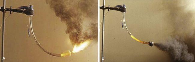
FIGURE 31-37 A, Burning endotracheal (ET) tube with a high concentration of O2 or O2/N2O will exhibit a “blowtorch” effect. B, A burning ET tube will produce a large amount of debris. (Copyright ECRI Institute. Used with permission.)
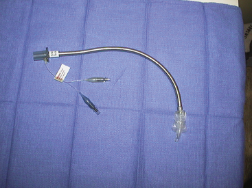
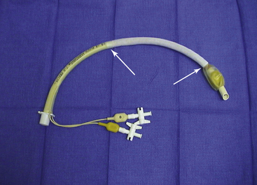
FIGURE 31-39 Lasertubus laser-resistant endotracheal tube (Rüsch, Duluth, GA). Arrows denote laser-resistant covering.
Another potential source of ignition for an OR fire is the ESU.109,110 A typical example of how an ESU could cause ignition would be during a tonsillectomy in a child in whom the anesthesiologist was using an uncuffed, flammable endotracheal tube. In this case, the oxygen or oxygen–nitrous oxide mixture could leak around the endotracheal tube and pool at the operative site, providing an oxidizer-enriched environment. When the surgeon uses the ESU or laser to cauterize the tonsil bed, the combination of a high concentration of oxidizer (O2 or an O2/N2O mixture), fuel (endotracheal tube), and ignition source (the ESU or laser) could easily start a fire.111,112
The best way to prevent this type of fire is to take steps to prevent the three legs of the fire triad from coming together. For example, mixing the oxygen with air will keep the inspired oxygen concentration as low as possible, thus reducing the available oxidizer. Another possibility would be to place wet pledgets around the endotracheal tube, which would prevent the escape of oxygen or oxygen–nitrous oxide mixture from the trachea into the operative field; this reduces the available oxidizer and would keep the endotracheal tube and tissues from becoming desiccated, thus reducing their suitability as fuel sources. However, the pledgets must be kept moist, lest they dry out and become an additional source of fuel for a fire.
A related situation that requires a different solution can arise when a critically ill patient requires a tracheostomy.113,114 These patients may require very high concentrations of inspired oxygen to maintain tissue oxygenation so that any decrease in inspired oxygen concentration or interruption of ventilation would not be tolerated. In this circumstance, the best option for preventing a fire would be to avoid the use of electrocautery (ignition source) when the surgeon enters the trachea.
The Nd:YAG laser can be used to treat tumors of the lower trachea and mainstem bronchi. Most commonly, the surgeon will use a fiberoptic bronchoscope (FOB) and pass the laser fiber through the suction port of the bronchoscope. The FOB can be used in conjunction with a rigid metal bronchoscope or can be passed through an 8.5 or 9.0 mm PVC endotracheal tube. A special laser-resistant tube would not be used in this circumstance, because the FOB and laser fiber pass through the endotracheal tube and focus on tissue distal to the tube. Fire safety precautions available in this setting include titrating the concentration of inspired oxygen to as low a concentration as the patient can tolerate, while maintaining a saturation of between 90% and 95%, ideally keeping the inspired oxygen below 30%, keeping the tip of the endotracheal tube and FOB away from the site of surgery and out of the “line of fire” of the laser, and removing charred and desiccated tissue from the surgical field.
The use of a rigid metal bronchoscope instead of an endotracheal tube will eliminate the possibility of setting the tube on fire but does not eliminate the possibility of setting the FOB on fire. This would also necessitate the use of a jet Venturi system to ventilate the patient, which would in turn deliver an inspired oxygen concentration of between 40% and 60%.
A number of basic safety precautions should be taken whenever a laser is used in surgery. Because laser light can be reflected off any metal surface, it is important that all OR personnel wear protective goggles specific to the type of laser being used. The anesthesiologist must be aware that laser goggles may make it difficult to read certain monitor displays. In addition, it is important that the patient’s eyes be covered with wet gauze or eye packs. In addition, OR personnel should wear high-filtration masks, because the laser “plume” may contain vaporized virus particles or chemical toxins. Finally, all doors to the OR should bear warning signs that a laser is in use, and all windows should be covered with black window shades.
Laparoscopic surgery in the abdomen is another potential risk for a surgical fire. Ordinarily, the abdomen is insufflated with carbon dioxide, which does not support combustion. It is important to verify that, indeed, only carbon dioxide is being used, as erroneous inclusion of oxygen can be disastrous.115,116 Also, nitrous oxide administered to the patient as part of the anesthetic can, over 30 minutes, diffuse into the abdominal cavity and attain a concentration that could support combustion.117 In fact, when sampling the abdominal gas contents after 30 minutes, the mean nitrous oxide concentration was 36%; however, in certain patients it reached a concentration of 47%. Both methane and hydrogen are flammable gases that are frequently present in bowel gas in significant concentrations. Methane concentration in bowel gas can be up to 56%, and hydrogen has been reported as high as 69%. With the maximum abdominal concentration of 47% nitrous oxide mixed with carbon dioxide, it would require the maximum of 56% of methane to be flammable. Therefore, this represents a relatively small hazard. In contrast, a concentration of 69% hydrogen is flammable if the nitrous oxide concentration is above 29%. Therefore a fire is possible if the surgeon enters the bowel while using the ESU, with a high concentration of hydrogen and an intraabdominal nitrous oxide content above 29%.
In recent years, fires on the patient seem to have become the most frequent type of OR fire. These cases occur most often during surgery in and around the head and neck, where the patient is receiving monitored anesthesia care, and supplemental oxygen is being administered by either a face mask or nasal cannula.118-122 In these cases, the oxygen can collect under the drapes if it is not properly vented; and when the surgeon uses the ESU or the laser, a fire can easily start. There are many things that can act as fuel, such as the surgical towels, paper drapes, disinfecting preparation solutions, sponges, plastic tubing from the oxygen face mask, and even the body hair. These fires start very quickly and can turn into an intense blaze in only a few seconds. Even if the fire is quickly extinguished, the patient will usually sustain significant burns.
The majority of OR fires occur with monitored anesthesia care during head and neck surgery. Invariably, this involves an oxygen-enriched atmosphere, because 75% of surgical fires are oxygen enriched. Currently, the Anesthesia Patient Safety Foundation (APSF) and ECRI Institute recommend that there be no open delivery of oxygen during these cases.85,123 If the patient needs increased levels of sedation during a time when the surgeon is using the ESU or laser, the airway should be secured with a laryngeal mask airway (LMA) or an endotracheal tube. Occasionally exceptional cases exist, in which the patient and the anesthesiologist need to communicate. An example of this might be a carotid endarterectomy or an awake craniotomy. In these cases it may be safe to use an FiO2 up to 30%. Preferably, the patient should receive only room air during these cases.
The most important principle that the anesthesiologist has to keep in mind to minimize the risk of fire is to titrate the inspired oxygen to the lowest amount necessary to keep patient’s oxygenation within safe levels. If the anesthesia machine has the ability to deliver air, the nasal cannula or face mask can be attached to the anesthesia circuit using a small (No. 3 or 4) 15-mm endotracheal tube adapter124 attached to the right-angle elbow of the circuit. If the anesthesia machine is equipped with an auxiliary oxygen flowmeter that has a removable nipple adapter, a humidifier can be installed in place of the nipple adapter. The humidifier has a Venturi mechanism through which room air is entrained; thus the oxygen concentration delivered to the face mask can be varied from 28% to 100%. Finally, if this machine has a common gas outlet that is easily accessible, a nasal cannula or face mask can be attached at this point using the same small (3 or 4 mm) endotracheal tube adapter (Fig. 31-40). If it is necessary to deliver more than 30% oxygen to the patient, delivering 5 to 10 L/min of air under the drapes will dilute the oxygen, and the oxygen should always be discontinued at least 1 minute before the surgeon uses the ESU. Also, the bipolar ESU is preferable to the monopolar ESU, and it is important that the drapes be arranged in such a manner that no oxygen buildup can occur beneath them. Tenting the drapes and having the surgeon use an adhesive sticky drape that seals the operative site from the oxygen flow are steps that will help reduce the risk of a fire.
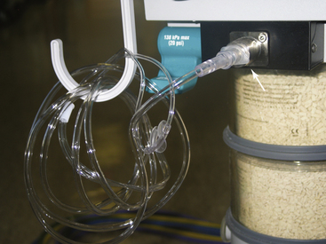
FIGURE 31-40 A nasal cannula connected to the alternate fresh gas outlet (arrow) on a Datex-Ohmeda Aestiva (GE Healthcare, Waukesha, WI) anesthesia machine.
It is possible to discontinue the use of oxygen before the surgeon plans to use the electrocautery or laser. This would have to be done several minutes beforehand in order to allow any built-up oxygen to dissipate. If the surgeon is planning to use the electrocautery or laser during the entire case, this may not be practical. Also, the bipolar ESU is preferable to the monopolar ESU in this situation.
Some newer surgical preparation solutions can contribute to surgical fires.125,126 These solutions typically come prepackaged in a “paint stick” applicator with a sponge on the end; the DuraPrep (St. Paul, MN) consists of iodophor mixed with 74% isopropyl alcohol, which is highly flammable and can easily provide fuel for an OR fire. In 2001, Barker and Polson118 reported just such a case. In a laboratory re-creation, they found that if the DuraPrep had been allowed to dry completely (4 to 5 min), the fire would not have occured (Fig. 31-41). The other problem with these types of preparation solutions is that small pools of the solution can accumulate if the person doing the preparation is not careful. The alcohol in these small puddles will continue to evaporate for a period of time, and the alcohol vapors are also extremely flammable. Flammable skin preparation solutions should be allowed to dry and puddles should be wiped up before the site is draped (Fig. 31-42).
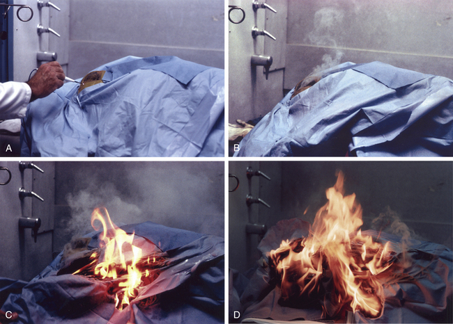
FIGURE 31-41 Simulation of fire caused by electricosurgical unit (ESU) electrode during surgery. A, Mannequin prepared and draped for surgery. An ESU monopolar pencil electrode is applied to the operative site at the start of surgery. B, Six seconds after ESU application, smoke appears from under the drapes. C, Fourteen seconds after ESU application, flames burst through the drapes. D, Twenty-four seconds after ESU application, the patient’s head and drapes in flames. (From Barker SJ, Polson JS: Fire in the operating room: a case report and laboratory study. Anesth Analg 2001; 93:960. Used with permission.)
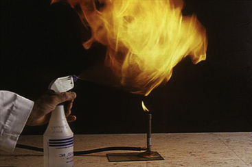
FIGURE 31-42 A demonstration of the intense heat and flame present in an alcohol fire. (Photograph courtesy Marc Bruley, ECRI Institute. Reprinted with permission. Copyright 2009, ECRI Institute, www.ecri.org.)
It is important to bear in mind that halogenation of hydrocarbon anesthetics confers relative, but not absolute, resistance to combustion. Even the newer, “nonflammable” volatile anesthetics can, under certain circumstances, present fire hazards. For example, sevoflurane is nonflammable in air but can serve as a fuel at concentrations as low as 11% in oxygen and 10% in nitrous oxide.127 In addition, sevoflurane and desiccated carbon dioxide absorbent, both soda lime and Baralyme, can undergo exothermic chemical reactions that have been implicated in several fires that involved the anesthesia breathing circuit.128-131 In 2003, the manufacturer of sevoflurane published a “Dear Health Care Provider” letter and advisory alert.132 To prevent futures fires, the manufacturer of sevoflurane has recommended that anesthesiologists use several measures to prevent fire that include avoiding the use of desiccated carbon dioxide absorbent and monitoring the temperature of the absorbers and the inspired concentration of sevoflurane. If elevated temperatures or an inspired sevoflurane concentration that differs unexpectedly from the vaporizer setting is detected, it is recommended that the patient be disconnected from the anesthesia circuit and monitored for signs of thermal or chemical injury and that the carbon dioxide absorbent be removed from the circuit and/or replaced.
Another way to prevent this type of fire is to use a carbon dioxide absorbent that does not contain a strong alkali, as do soda lime and Baralyme (no longer manufactured). Amsorb (Amstrong Medical Limited, Coleraine, UK) is a carbon dioxide absorbent that contains calcium hydroxide and calcium chloride but no strong alkali.133 In experimental studies, Amsorb was found to be unreactive with currently used volatile anesthetics, and it did not produce carbon monoxide or compound A with desiccated absorbent; therefore it will not interact with sevoflurane and undergo an exothermic chemical reaction.
If a fire does occur, it is important to extinguish it as soon as possible. The first step is to interrupt the fire triad by removing one component. This is usually best accomplished by removing the oxidizer from the fire. Therefore if an endotracheal tube is on fire, disconnecting the circuit from the tube or disconnecting the inspiratory limb of the circuit will usually result in the fire immediately going out. Simultaneously the surgeon should remove the burning tracheal tube. Once the fire is extinguished, the airway is inspected via bronchoscopy, and the patient may be reintubated.
If the fire is on the patient, the most rapid and effective method to extinguish it is with a basin of saline. A sheet or towel may also be used. If the drapes are burning, particularly paper drapes, they must be removed and put on the floor. Paper drapes are impervious to water, thus throwing water or saline on them will do little to extinguish the fire. Once the burning drapes are removed from the patient, the fire can then be extinguished with a fire extinguisher. In most OR fires, the sprinkler system is not activated, because sprinklers are not located directly over the OR table, and OR fires seldom get hot enough to activate them.
All OR personnel should receive OR fire safety education, which should include training in institutional fire safety protocols and learning the location and operation of the fire extinguishers. Fire safety education, including fire drills, allows each member of the OR team to learn and practice what his or her responsibilities and actions should be if a fire were to occur. Fire drills are an important part of the plan and can help personnel become familiar with the exits, evacuation routes, locations of fire extinguishers, and how to shut off medical gas and electrical supplies. Although institutional fire safety protocols vary, the general principles of responding to an OR fire can be summarized by the mnemonic ERASE: extinguish, rescue, activate, shut, and evaluate. Generally speaking, the team should first attempt to extinguish any fire on, in, or near the patient; depending on the situation, this may include the use of saline or a carbon dioxide fire extinguisher (this will be discussed later). If the initial attempts at extinguishing the fire are unsuccessful, the patient and all other persons at risk should be rescued, the OR should be evacuated if possible, and someone should activate the fire alarm. Once the OR is emptied of personnel, the doors should be shut, and the medical gas supply to the room should be shut off. The patient should then be evaluated, and any injuries should be appropriately managed.
Fire extinguishers are divided into three classes, termed A, B, and C based on the types of fires for which they are best suited. Class A extinguishers are used on paper, cloth, and plastic materials; class B extinguishers are used for fires when liquids or greases are involved; and class C extinguishers are used for energized electrical equipment. A single fire extinguisher may be useful for any one, two, or all three types of fires. Probably the best fire extinguisher for the OR is the carbon dioxide extinguisher, which can be used on class B and C fires and some class A fires. Other extinguishers provide a water mist or new environmentally friendly fluorocarbons, and these have replaced the Halon fire extinguisher. Finally, many ORs are equipped with a fire hose that supplies pressurized water at a rate of 50 gallons/min. Such equipment is best left to the fire department to use, except to rescue someone from a fire. In order to effectively use a fire extinguisher, the acronym PASS can be helpful: it stands for pull the pin to activate the fire extinguisher, aim at the base of the fire, squeeze the trigger, and sweep the extinguisher back and forth across the base of the fire. When responding to a fire, the acronym RACE is useful: it stands for rescue, alarm, confine, and extinguish. Clearly, having a plan that everyone is familiar with will greatly facilitate extinguishing any fire and will minimize harm to patients, personnel, and equipment. However, neither fire drills nor the presence and use of fire extinguishers should be relied on to provide a fire-safe operating environment. Only through heightened awareness, continuing education, and ongoing communication can the fire triad be avoided and the risk of an OR fire minimized.
References
1. Harpell T.R. Electrical shock hazards in the hospital environment: their causes and cures. Can Hosp. 1970;47:48.
2. Buczko G.B., McKay W.P.S. Electrical safety in the operating room. Can J Anaesth. 1987;34:315.
3. Wald A. Electrical safety in medicine. In: Skalak R., Chien S., eds. Handbook of bioengineering. New York: McGraw-Hill; 1987:34.
4. Dalziel C.F., Massoglia F.P. Let-go currents and voltages. AIEE Trans. 1956;75:49.
5. Bruner J.M.R., Aronow S., Cavicchi R.V. Electrical incidents in a large hospital: a 42 month register. JAAMI. 1972;6:222.
6. Bernstein M.S. Isolated power and line isolation monitors. Biomed Instrum Technol. 1990;24:221.
7. Gibby G.L. Shock and electrocution. In: Lobato E.B., Gravenstein N., Kirby R.R., eds. Complications in anesthesiology. Philadelphia: Wolters Kluwer/Lippincott Williams & Wilkins; 2008:780.
8. Weinberg D.I., Artley J.L., Whalen R.E., et al. Electric shock hazards in cardiac catheterization. Circ Res. 1962;11:1004.
9. Starmer C.F., Whalen R.E. Current density and electrically induced ventricular fibrillation. Med Instrum. 1973;7:158.
10. Whalen R.E., Starmer C.F., McIntosh H.D. Electrical hazards associated with cardiac pacemaking. Ann N Y Acad Sci. 1964;111:922.
11. Raftery E.B., Green H.L., Yacoub M.H. Disturbances of heart rhythm produced by 50-Hz leakage currents in human subjects. Cardiovasc Res. 1975;9:263.
12. Hull C.J. Electrocution hazards in the operating theatre. Br J Anaesth. 1978;50:647.
13. Watson A.B., Wright J.S., Loughman J. Electrical thresholds for ventricular fibrillation in man. Med J Aust. 1973;1:1179.
14. Furman S., Schwedel J.B., Robinson G., et al. Use of an intracardiac pacemaker in the control of heart block. Surgery. 1961;49:98.
15. Noordijk J.A., Oey F.J.I., Tebra W. Myocardial electrodes and the danger of ventricular fibrillation. Lancet. 1961;1:975.
16. Pengelly L.D., Klassen G.A. Myocardial electrodes and the danger of ventricular fibrillation. Lancet. 1961;1:1234.
17. Rowe G.G., Zarnstorff W.C. Ventricular fibrillation during selective angiocardiography. JAMA. 1965;192:947.
18. Hopps J.A., Roy O.S. Electrical hazards in cardiac diagnosis and treatment. Med Electr Biol Eng. 1963;1:133.
19. Baas L.S., Beery T.A., Hickey C.S. Care and safety of pacemaker electrodes in intensive care and telemetry nursing units. Am J Crit Care. 1997;6:301.
20. Leeming M.N. Protection of the electrically susceptible patient: a discussion of systems and methods. Anesthesiology. 1973;38:370.
21. McNulty S.E., Cooper M., Staudt S. Transmitted radiofrequency current through a flow directed pulmonary artery catheter. Anesth Analg. 1994;78:587.
22. Cromwell L., Weibell F.J., Pfeiffer E.A. Biomedical instrumentation and measurements, ed 2. Englewood Cliffs, NJ: Prentice-Hall; 1980. p 430
23. Edwards N.K. Specialized electrical grounding needs. Clin Perinatol. 1976;3:367.
24. Goldwyn R.M. Bovie: the man and the machine. Ann Plast Surg. 1979;2:135.
25. Lichter I., Borrie J., Miller W.M. Radio-frequency hazards with cardiac pacemakers. Br Med J. 1965;1:1513.
26. Dornette W.H.L. An electrically safe surgical environment. Arch Surg. 1973;107:567.
27. Klop W.M., Lohuis P.J., Strating R.P., Mulder W. Ventricullar fibrillation caused by electrocoagulation during laparoscopic surgery. Surg Endosc. 2002;16:362.
28. Fu Q., Cao P., Mi W.D., Zhang H. Ventricular fibrillation caused by electrocoagulation during thoracic surgery. Acta Anaesthesiol Scand. 2010;54:256.
29. Yan C.Y., Cai X.J., Wang Y.F., Yu H. Ventricular fibrillation caused by electrocoagulation in monopolar mode during laparoscopic subphrenic mass resection. Surg Endosc. 2011;25:309–311.
30. Dalibon N., Pelle-Lancien E., Puyo P., Leclerc J.F., Fischler M. Recurrent asystotle during electrocauterization: an uncommon hazard in common situations. Eur J Anaesthesiol. 2005;22:476–478.
31. Cushing H. Electro-surgery as an aid to the removal of intracranial tumors: with a preliminary note on a new surgical-current generator by W.T. Bovie. Surg Gynecol Obstet. 1928;47:751.
32. Meathe E.A. Electrical safety for patients and anesthetists. In: Saidman L.J., Smith N.T., eds. Monitoring in anesthesia. ed 2. Boston: Butterworth; 1984:497.
33. Rolly G. Two cases of burns caused by misuse of coagulation unit and monitoring. Acta Anaesthesiol Belg. 1978;29:313.
34. Parker E.O. Electrosurgical burn at the site of an esophageal temperature probe. Anesthesiology. 1984;61:93.
35. Schneider A.J.L., Apple H.P., Braun R.T. Electrosurgical burns at skin temperature probes. Anesthesiology. 1977;47:72.
36. Bloch E.C., Burton L.W. Electrosurgical burn while using a battery-operated Doppler monitor. Anesth Analg. 1979;58:339.
37. Becker C.M., Malhotra I.V., Hedley-Whyte J. The distribution of radiofrequency current and burns. Anesthesiology. 1973;38:106.
38. Jones C.M., Pierre K.B., Nicoud I.B., Stain S.C., Melvin W.V. Electrosurgery. Curr Surg. 2006;63:458–463.
39. Mitchell J.P. The isolated circuit diathermy. Ann R Coll Surg Engl. 1979;61:287.
40. Titel J.H., El Etr A.A. Fibrillation resulting from pacemaker electrodes and electrocautery during surgery. Anesthesiology. 1968;29:845.
41. Domino K.B., Smith T.C. Electrocautery-induced reprogramming of a pacemaker using a precordial magnet. Anesth Analg. 1983;62:609.
42. Damaged reusable ESU return electrode cables. Health Devices. 1985;14:214.
43. Sparking from and ignition of damaged electrosurgical electrode cables. Health Devices. 1998;27:301.
44. Mirowski M., Reid P.R., Mower M.M., et al. Termination of malignant ventricular arrhythmias with an implanted automatic defibrillator in human beings. N Engl J Med. 1980;303:322.
45. Crozier I.G., Ward D.E. Automatic implantable defribrillators. Br J Hosp Med. 1988;40:136.
46. Elefteriades J.A., Biblo L.A., Batsford W.P., et al. Evolving patterns in the surgical treatment of malignant ventricular tachyarrhythmias. Ann Thorac Surg. 1990;49:94.
47. Carr C.M.E., Whiteley S.M. The automatic implantable cardioverter-defibrillator. Anaesthesia. 1991;46:737.
48. Starmer C.F., McIntosh H.D., Whalen R.E. Electrical hazards and cardiovascular function. N Engl J Med. 1971;284:181.
49. Albisser A.M., Parson I.D., Pask B.A. A survey of the grounding systems in several large hospitals. Med Instrum. 1973;7:297.
50. McLaughlin A.J., Campkin N.T. Electrical safety: a reminder (letter). Anaesthesia. 1998;53:608.
51. Nixon M.C., Ghurye M. Electrical failure in theatre—a consequence of complacency? Anaesthesia. 1997;52:88.
52. Medical Devices; Establishment of a Performance Standard for Electrode Lead Wires and Patient Cables. Federal Register. 1997;62:25477.
53. Emergency Care Research Institute. FDA establishes performance standards for electrode lead wires. Health Devices. 1998;27:34.
54. National Fire Protection Association: NFPA 99, Health Care Facilities Code, 2012 Edition, Article 6.4.4.1.1.2 Maintenance and Testing of Alternate Power Source and Transfer Switches. Quincy, MA.
55. National Fire Protection Association: NFPA 110, Standard for Emergency and Standby Power Systems, Chapter 8, Quincy MA.
56. Carpenter T., Robinson S.T. Response to a partial power failure in the operating room. Anesth Analg. 2010;110:1644–1646.
57. Eichhorn J.H., Hessel E.A. Electrical power failure in the operating room: a neglected topic in anesthesia safety. Anesth Analg. 2010;110:1519–1521.
58. Jones R.P., Conway D.H. The effect of electromagnetic interference from mobile communication on the performance of intensive care ventilators. Eur J Anaesthesiol. 2005;22:578.
59. Lawrentschuk N., Bolton D.M. Mobile phone interference with medical equipment and its clinical relevance: a systematic review. Med J Aust. 2004;181:145.
60. Hayes D.L., Wang P.J., Reynolds D.W., et al. Interference with cardiac pacemakers by cellular telephones. N Engl J Med. 1997;336:1473.
61. Schlegel R.E., Grant F.H., Raman S., Reynolds D. Electromagnetic compatibility study of the in vitro interaction of wireless phones with cardiac pacemakers. Biomed Instrum Technol. 1998;32:645.
62. Chen W.H., Lau C.P., Leung S.K., et al. Interference of cellular phones with implanted permanent pacemakers. Clin Cardiol. 1996;19:881.
63. Fetter J.G., Ivans V., Benditt D.G., Collins J. Digital cellular telephone interaction with implantable cardioverter-defibrillators. J Am Coll Cardiol. 1998;21:623.
64. Emergency Care Research Institute. Cell phones and walkie-talkies: Is it time to relax your restrictive policies? Health Devices. 1999;28:409.
65. Adler D., Margulies L., Mahler Y., Israeli A. Measurements of electromagnetic fields radiated from communication equipment and of environmental electromagnetic noise: impact on the use of communication equipment within the hospital. Biomed Instrum Technol. 1998;32:581.
66. Schwartz J.J., Ehrenwerth J. Electrical safety. In: Lake C.L., Hines R.H., Blitt C., eds. Clinical monitoring: practical applications for anesthesia and critical care. Philadelphia: WB Saunders, 2000.
67. Kermit E., Staewen W.S. Isolated power systems: historical perspective and update on regulations. Biomed Tech Today. 1986;1:86.
68. National Fire Protection Association. National electric code (ANSI/NFPA 70-1984). Quincy, MA: NFPA; 1984.
69. National Fire Protection Association, NFPA-99, Health Care Facilities Code. Quincy, MA: NFPA; 2012. 2012 Edition
70. Bruner J.M.R., Leonard P.F. Electricity, safety and the patient. Chicago: Year Book Medical Publishers; 1989. p 300
71. Matjasko M.J., Ashman M.N. All you need to know about electrical safety in the operating room. Barash P.G., Deutsch S., Tinker J., eds. ASA refresher courses in anesthesiology. Philadelphia: JB Lippincott; 1990;vol. 18:251.
72. Lennon R.L., Leonard P.F. A hitherto unreported virtue of the isolated power system (letter). Anesth Analg. 1987;66:1056.
73. Barker S.J., Doyle D.J. Electrical safety in the operating room: dry versus wet. Anesth Analg. 2010;110:1517–1518.
74. Gilbert T.B., Shaffer M., Matthews M. Electrical shock by dislodged spark gap in bipolar electrosurgical device. Anesth Analg. 1991;73:355.
75. Van Kerchhove K. Re-evaluating the isolated power equation. Electrical Products and Solutions. March 2008:25–27.
76. Day F.J. Electrical safety revisited: a new wrinkle. Anesthesiology. 1994;80:220.
77. Wills J.H., Ehrenwerth J., Rogers D. Electrical injury to a nurse due to conductive fluid in an operating room designated as a dry location. Anesth Analg. 2010;110:1647–1649.
78. August D.A. Locked out of a box and a process. Anesth Analg. 2011;112:1248–1249.
79. Barker S.J. In response to August DA. Anesth Analg. 2011;112:1249.
80. Litt L., Ehrenwerth J. Electrical safety in the operating room: important old wine, disguised in new bottles. Anesth Analg. 1994;78:417.
81. Seifert H.A. Fire safety in the operating room. In: Eisenkraft J.B., ed. Progress in anesthesiology. Philadelphia: W.B. Saunders, 1994.
82. Neufeld G.R. Fires and explosions. In: Orkin K., Cooperman L.H., eds. Complications in anesthesiology. Philadelphia: Lippincott; 1983:671.
83. Moxon M.A. Fire in the operating room. Anaesthesia. 1986;41:543.
84. Vickers M.D. Fire and explosion hazards in operating theatres. Br J Anaesth. 1978;50:659.
85. ECRI Institute. New clinical guide to surgical fire prevention. Health Devices. 2009;38(10):314–332.
86. Caplan R.A., Barker S.J., Connis R.T., et al. Practice advisory for the prevention and management of operating room fires. Anesthesiology. 2008;108:786–801.
87. de Richemond A.L. The patient is on fire!. Health Devices. 1992;21:19.
88. Cameron B.G., Ingram G.S. Flammability of drape materials in nitrous oxide and oxygen. Anesthesiology. 1971;26:218.
89. Johnson R.M., Smith C.V., Leggett K. Flammability of disposable surgical drapes. Arch Ophthalmol. 1976;94:1327.
90. Simpson J.I., Wolf G.L. Flammability of esophageal stethoscopes, nasogastric tubes, feeding tubes, and nasopharyngeal airways in oxygen- and nitrous oxide–enriched atmospheres. Anesth Analg. 1988;67:1093.
91. Ponath R.E. Preventing surgical fires. JAMA. 1984;252:1762.
92. Katz J., Campbell L. Fire during thoracotomy: a need to control the inspired oxygen concentration. Anesth Analg. 2005;101:612.
93. Wolf G., Sidebotham G.W., Lazard J.L.P. Laser ignition of surgical drape materials in air 50% oxygen, and 95% oxygen. Anesthesiology. 2004;100:1167–1171.
94. Food and Drug Administration: Surgical Fires Reported January 1995–June 1998. FDA Databases MDR/MAUDE, 1999.
95. Rampil I.J. Anesthetic considerations for laser surgery. Anesth Analg. 1992;74:424.
96. Pashayan A.G., Ehrenwerth J. Lasers and electrical safety in the operating room. In: Ehrenwerth J., Eisenkraft J.B., eds. Anesthesia equipment: principles and applications. St. Louis: Mosby, 1993.
97. Emergency Care Research Institute. Lasers in medicine—an introduction. Health Devices. 1984;13:151.
98. Casey K.R., Fairfax W.R., Smith S.J., et al. Intratracheal fire ignited by the Nd:YAG laser during treatment of tracheal stenosis. Chest. 1983;84:295.
99. Burgess G.E., LeJeune F.E. Endotracheal tube ignition during laser surgery of the larynx. Arch Otolaryngol. 1979;105:561.
100. Cozine K., Rosenbaum L.M., Askanazi J., et al. Laser induced endotracheal tube fire. Anesthesiology. 1981;55:583.
101. Geffin B., Shapshay S.M., Bellack G.S., et al. Flammability of endotracheal tubes during Nd:YAG laser application in the airway. Anesthesiology. 1986;65:511.
102. Hirshman C.A., Smith J. Indirect ignition of the endotracheal tube during carbon dioxide laser surgery. Arch Otolaryngol. 1980;106:639.
103. Krawtz S., Mehta A.C., Weidemann H.P., et al. Nd:YAG laser-induced endobronchial burn. Chest. 1989;95:916.
104. Goldblum K.B. Oxygen index: Key to precise flammability ratings. Soc Plastics Engineers J. 1969;25:50–52.
105. Wolf G.L., Simpson J.I. Flammability of endotracheal tubes in oxygen and nitrous oxide enriched atmosphere. Anesthesiology. 1987;67:236.
106. de Richemond A.L. Laser resistant endotracheal tubes: protection against oxygen-enriched airway fires during surgery?. Stoltzfus J.M., McIlroy K., eds. Flammability and sensitivity of material in oxygen-enriched atmospheres. Philadelphia: American Society for Testing and Materials; 1991;vol 5:157. ASTM STP 1111
107. Emergency Care Research Institute (ECRI). Airway fires: reducing the risk during laser surgery. Health Devices. 1990;19:109.
108. Emergency Care Research Institute. Laser-resistant tracheal tubes (evaluation). Health Devices. 1992;21:4.
109. Aly A., McIlwain M., Ward M. Electrosurgery-induced endotracheal tube ignition during tracheotomy. Ann Otol Rhinol Laryngol. 1991;100:31.
110. Simpson J.I., Wolf G.L. Endotracheal tube fire ignited by pharyngeal electrocautery. Anesthesiology. 1986;65:76.
111. Gupte S.R. Gauze fire in the oral cavity: a case report. Anesth Analg. 1972;51:645.
112. Snow J.C., Norton M.L., Saluja T.S., et al. Fire hazard during CO2 laser microsurgery on the larynx and trachea. Anesth Analg. 1975;55:146.
113. Lew E.O., Mittleman R.E., Murray D. Tube ignition by electrocautery during tracheostomy: Case report with autopsy findings. J Forensic Sci. 1991;36:1586.
114. Marsh B., Riley D.H. Double-lumen tube fire during tracheostomy. Anesthesiology. 1992;76:480.
115. Neuman G.G., Sidebotham G., Negoianu E., et al. Laparoscopy explosion hazards with nitrous oxide. Anesthesiology. 1993;78:875.
116. Di Pierro G.B., Besmer I., Hefermehl L.J., et al. Intra-abdominal fire due to insufflating oxygen instead of carbon dioxide during robot-assisted radical prostatectomy: case report and literature review. Eur Urol. 2010;58:626–628.
117. Greilich P.E., Greilich N.B., Froelich E.G. Intraabdominal fire during laparoscopic cholecystectomy. Anesthesiology. 1995;83:871.
118. Barker S.J., Polson J.S. Fire in the operating room: a case report and laboratory study. Anesth Analg. 2001;93:960.
119. Bruley M.E., Lavanchy C. Oxygen-enriched fires during surgery of the head and neck. In: Symposium on flammability and sensitivity of material in oxygen-enriched atmospheres (ASTM STP 1040). Philadelphia: American Society for Testing and Materials; 1989:392.
120. de Richemond A.L., Bruley M.E. Head and neck surgical fires. In: Eisele D.W., ed. Complications in head and neck surgery. St. Louis: Mosby, 1993.
121. ECRI. Fires during surgery of the head and neck area (hazard). Health Devices. 1979;9:50.
122. Ramanathan S., Capan L., Chalon J., et al. Mini-environmental control under the drapes during operations on eyes of conscious patients. Anesthesiology. 1978;48:286.
123. Anesthesia Patient Safety Foundation. Prevention and Management of Operating Room Fires (Video). Apsf.org. 2010.
124. Lampotang S., Gravenstein N., Paulus D.A., Gravenstein D. Reducing the incidence of surgical fires: supplying nasal cannulae with sub-100% O2 gas mixtures from anesthesia machines. Anesth Analg. 2005;101:1407–1412.
125. Patel R., Chavda K.D., Hukkeri S. Surgical field fire and skin burns caused by alcohol-based skin preparation. J Emerg Trauma Shock. 2010;3(3):305.
126. Prasad R., Quezado Z., St. Andre A., O’Grady N.P. Fires in the operating room and intensive care unit: awareness is the key to prevention. Anesth Analg. 2006;102:172–174.
127. Wallin R.F., Regan B.M., Napoli M.D., Stern I.J. Sevoflurane: a new inhalational anesthetic agent. Anesth Analg. 1975;54:758.
128. Fatheree R.S., Leighton B.L. Acute respiratory syndrome after an exothermic baralyme-sevoflurane reaction. Anesthesiology. 2004;101:531.
129. Castro B.A., Freedman L.A., Craig W.L., Lynch C. Explosion within an anesthesia machine: baralyme, high fresh gas flows and sevoflurane concentration. Anesthesiology. 2004;101:537.
130. Wu J., Previte J.P., Adler E., et al. Spontaneous ignition, explosion and fire with sevoflurane and barium hydroxide lime. Anesthesiology. 2004;101:534.
131. Abbott A. Dear healthcare provider (letter). http://www.fda.gov/downloads/Safety/MedWatch/SafetyInformation/SafetyAlertsforHumanMedicalProducts/UCM169499.pdf. Available at
132. Murray J.M., Renfrew C.W., Bedi A., et al. Amsorb: a new carbon dioxide absorbent for use in anesthetic breathing systems. Anesthesiology. 1999;91:1342.
133. Laster M., Roth P., Eger E.I. Fires from the interaction of anesthetics with desiccated absorbent. Anesth Analg. 2004;99:769.
∗This chapter and the images contained herein were developed in whole from Clinical Anesthesia (ed. 7, Wolters Kluwer Health/Lippincott Williams & Wilkins; Barash PG, Cullen BF, Stoelting RK, et al., editors) and Anesthesia Equipment: Principals and Applications (ed. 2, Elsevier; Ehrenwerth J, Eisenkraft JB, Berry JM, editors) with permission of the editors and publishers.