CHAPTER 8 Pacemaker Rhythms
INTRODUCTION
A cardiac pacemaker is a battery-powered device that delivers an electrical current to the heart to stimulate depolarization. A pacemaker system consists of a pulse generator (i.e., the power source) and pacing leads. The pulse generator houses a battery and electronic circuitry. The circuitry works like a computer, converting energy from the battery into electrical pulses. A lithium battery is usually the power source for implanted pacemakers and implantable cardioverter-defibrillators (ICDs), whereas a 9-volt alkaline battery is usually used to power a temporary external pulse generator. A pacing lead is an insulated wire that is used to carry an electrical impulse from the pulse generator to the patient’s heart. It also carries information about the heart’s electrical activity back to the pacemaker. The pacemaker responds to the information received either by sending a pacing impulse to the heart (i.e., triggering) or by not sending a pacing impulse to the heart (i.e., inhibition).
PERMANENT PACEMAKERS AND IMPLANTABLE CARDIOVERTER-DEFIBRILLATORS
A permanent pacemaker is used to treat disorders of the sinoatrial (SA) node (e.g., bradycardias), disorders of the atrioventricular (AV) conduction pathways (e.g., second-degree AV block type II, third-degree AV block), or both, that produce signs and symptoms as a result of inadequate cardiac output. The pacemaker’s pulse generator is usually implanted under local anesthesia into the subcutaneous tissue of the anterior chest just below the right or left clavicle.
An ICD is a programmable device that can deliver a range of therapies (also called tiered-therapy) including defibrillation, antitachycardia pacing (i.e., overdrive pacing), synchronized cardioversion, and bradycardia pacing, depending on the dysrhythmia detected and how the device is programmed. A physician determines the appropriate therapies for each patient.
TEMPORARY PACEMAKERS
The pulse generator of a temporary pacemaker is located externally. Temporary pacing can be accomplished through transvenous, epicardial, or transcutaneous means.
Transvenous pacemakers stimulate the endocardium of the right atrium or ventricle (or both) by means of an electrode introduced into a central vein, such as the subclavian, femoral, brachial, internal jugular, or external jugular vein. Epicardial pacing is the placement of pacing leads directly onto or through the epicardium. Epicardial leads may be used when a patient is undergoing cardiac surgery and the outer surface of the heart is easy to reach.
Transcutaneous pacing (TCP) delivers pacing impulses to the heart using large electrodes that are placed on the patient’s chest. TCP is also called temporary external pacing or noninvasive pacing. TCP is indicated for significant bradycardias that are unresponsive to atropine therapy or when atropine is not immediately available or indicated. It may also be used as a bridge until transvenous pacing can be accomplished or the cause of the bradycardia is reversed (e.g., drug overdose, hyperkalemia). Standby pacing refers to the application of the pacing pads to the patient’s chest in anticipation of possible use, but pacing is not yet needed. For example, standby pacing is often warranted when second-degree AV block type II or third-degree AV block are present in the setting of acute myocardial infarction (MI). The range of output current of a transcutaneous pacemaker varies depending on the manufacturer. You must be familiar with your equipment before you need to use it.
PACING LEAD SYSTEMS
Pacemaker lead systems may consist of single, double, or multiple leads. The exposed portion of the pacing lead is called an electrode, which is placed in direct contact with the heart. Pacing, which is also called pacemaker firing, occurs when the pacemaker’s pulse generator delivers energy (milliamperes [mA]) through the pacing electrode to the myocardium. Evidence of pacing can be seen as a vertical line or spike on the electrocardiogram (ECG).
Capture is the successful conduction of an artificial pacemaker’s impulse through the myocardium, resulting in depolarization. Capture is obtained after the pacemaker electrode is properly positioned in the heart; with one-to-one capture, each pacing stimulus results in depolarization of the appropriate chamber. On the ECG, evidence of electrical capture can be seen as a pacemaker spike followed by an atrial or a ventricular complex, depending on the cardiac chamber that is being paced. Mechanical capture is assessed by palpating the patient’s pulse or by observing right atrial pressure, left atrial pressure, or pulmonary artery or arterial pressure waveforms.
A unipolar electrode has one pacing electrode that is located at its distal tip. The negative electrode is in contact with the cardiac tissue, and the pulse generator (located outside the heart) functions as the positive electrode. The pacemaker spike produced by a unipolar lead system is often large because of the distance between the positive and negative electrode. Unipolar leads are less commonly used than bipolar lead systems because of the potential for pacing the chest wall muscles and the susceptibility of the unipolar leads to electromagnetic interference.
A bipolar lead system contains a positive and negative electrode at the distal tip of the pacing lead wire (Figure 8-1). Most temporary transvenous pacemakers use a bipolar lead system. A permanent pacemaker may have either a bipolar or a unipolar lead system. The pacemaker spike produced by a bipolar lead system is smaller than that of a unipolar system because of the shorter distance between the positive and negative electrodes.

Figure 8-1 Bipolar and unipolar pacing. A, Pacemaker spike produced by a bipolar lead system. B, Pacemaker spike produced by a unipolar lead system.
Single-Chamber Pacemakers
A pacemaker that paces a single heart chamber, either the atrium or ventricle, has one lead placed in the heart. Atrial pacing is achieved by placing the pacing electrode in the right atrium. Stimulation of the atria produces a pacemaker spike on the ECG, followed by a P wave (Figure 8-2). Atrial pacing may be used when the SA node is diseased or damaged, but conduction through the AV junction and ventricles is normal. This type of pacemaker is ineffective if an AV block develops because it cannot pace the ventricles.

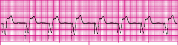
Ventricular pacing is accomplished by placing the pacing electrode in the right ventricle. Stimulation of the ventricles produces a pacemaker spike on the ECG followed by a wide QRS, resembling a ventricular ectopic beat (Figure 8-3). The QRS complex is wide because a paced impulse does not follow the normal conduction pathway in the heart. A single-chamber ventricular pacemaker can pace the ventricles but it cannot coordinate pacing with the patient’s intrinsic atrial rate. This results in asynchronous contraction of the atrium and ventricle (i.e., AV asynchrony). Because of this loss of AV synchrony, a ventricular demand pacemaker is rarely used in a patient with an intact SA node. Conversely, a ventricular demand pacemaker may be used for the patient with chronic atrial fibrillation.
Dual-Chamber Pacemakers
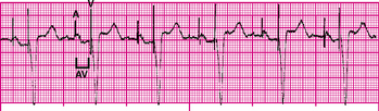
A dual-chamber pacemaker uses two leads: one lead is placed in the right atrium and the other in the right ventricle. Dual-chamber pacing is also called physiologic pacing. A dual-chamber pacemaker stimulates the right atrium and right ventricle sequentially (stimulating first the atrium, then the ventricle), mimicking normal cardiac physiology and thus preserving the atrial contribution to ventricular filling (i.e., atrial kick) (Figure 8-4).
Biventricular Pacemakers
A biventricular pacemaker has three leads; one lead for each ventricle and one lead for the right atrium. This device uses cardiac resynchronization therapy to restore normal simultaneous ventricular contraction for patients with heart failure, thereby improving cardiac output and exercise tolerance.
Fixed-Rate Pacemakers
A fixed-rate pacemaker, which is also known as an asynchronous pacemaker, continuously discharges at a preset rate (usually 70 to 80 impulses/min) regardless of the patient’s heart rate or metabolic demands. An advantage of the fixed-rate pacemaker is its simple circuitry, reducing the risk of pacemaker failure; however, this type of pacemaker does not sense the patient’s own cardiac rhythm. This may result in competition between the patient’s cardiac rhythm and that of the pacemaker. Ventricular tachycardia or ventricular fibrillation may be induced if the pacemaker were to fire during the T wave (i.e., the vulnerable period) of a preceding patient beat. Fixed-rate pacemakers are not often used today.
Demand Pacemakers
A demand pacemaker, which is also known as a synchronous or noncompetitive pacemaker, discharges only when the patient’s heart rate drops below the pacemaker’s base rate. For example, if the demand pacemaker was preset at a base rate of 70 impulses/min, it would sense the patient’s heart rate and allow electrical impulses to flow from the pacemaker through the pacing lead to stimulate the heart only when the rate fell below 70 beats/min. Demand pacemakers can be programmable or nonprogrammable. The voltage level and impulse rate are preset at the time of manufacture in nonprogrammable pacemakers.
PACEMAKER CODES
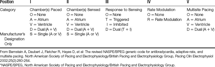
Pacemaker codes are used to assist in identifying a pacemaker’s preprogrammed pacing, sensing, and response functions (Table 8-1). The first letter of the code identifies the heart chamber (or chambers) paced (stimulated). A pacemaker used to pace only a single chamber is represented by either A (atrial) or V (ventricular). A pacemaker capable of pacing in both chambers is represented by D (dual). The second letter identifies the chamber of the heart where patient-initiated (i.e., intrinsic) electrical activity is sensed by the pacemaker. The third letter indicates how the pacemaker will respond when it senses patient-initiated electrical activity. The fourth letter identifies the availability of rate modulation (i.e., the pacemaker’s ability to adapt its rate to meet the body’s needs caused by increased physical activity and then increase or decrease the pacing rate accordingly). A pacemaker’s rate modulation capability may also be referred to as rate responsiveness or rate adaptation. The fifth letter denotes multisite pacing.
A defibrillator code was developed in 1993 and it is used to describe the capabilities and operation of ICDs (Table 8-2).
