It is highly unlikely that a dentist would be faulted for routinely using a rubber dam. Few procedures in dentistry are more universally accepted. Ironically, the infrequency of rubber dam use demonstrates that few dental procedures are more universally rejected as well.1
This paradox is further complicated by the reasons given for the rejection of rubber dam placement as a routine part of the daily practice of dentistry. Those who shun the technique cite patient disapproval, inconvenience, lack of necessity, and additional time requirements as the rationale for rejection.2 Advocates hold diametrically opposing views, indicating patient preference, work simplification and convenience, necessity, and an overall time savings.1, 3, 4 The dental student’s early experiences with rubber dam application often are negative because of a typical and expected lack of manual dexterity. The virtually total avoidance of rubber dam use, except during endodontic therapy, routinely begins immediately upon graduation.
A simplified technique, along with the average practitioner’s naturally acquired manual adeptness, allows placement of the rubber dam in 90 seconds or less to be a quickly attainable reality. With a minimum of practice, placement time can be reduced even further. The average application time (isolating an average of 4.6 teeth) of five private practitioners who routinely used rubber dam was 50.7 seconds.5
Rubber dam clamp selection
Selection of a rubber dam clamp can be confusing because of the vast array of available clamp sizes and styles. The basic assortment presented in table B-1, however, can accommodate virtually every clinical situation.
Table B-1
Rubber Dam Clamps
Winged Type
Wingless Type
Indication
14A
W14A
Most adult molars
14
W14
Small adult molars, adult premolars, and primary molars
8A
W8A
More aggressive clamp for adult molars
1
W1
Mandibular anterior teeth
211
212
Maxillary and mandibular anterior teeth (Class V restorations)
• 6 × 6-inch rubber dam, medium gauge (e.g., Hygenic Flexi Dam Rubber Dam Non Latex 6 × 6 Med, Coltene/Whaledent. Inc.)
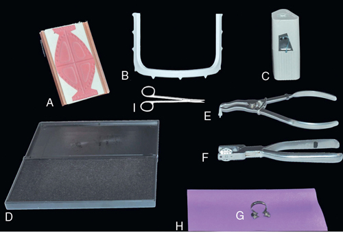
FIGURE B-1 Complete Rubber Dam Armamentarium A, Rubber dam rubber stamp (optional). B, 6 × 6-inch plastic U-shaped rubber dam frame. C, Dental floss. D, Stamp pad (optional). E, Rubber dam clamp forceps. F, Rubber dam hole punch. G, Rubber dam clamp. H, Rubber dam. I, Dental scissor.
• 6 × 6-inch plastic U-shaped rubber dam frame (e.g., Hygenic Rubber Dam Frame 6” (Plastic), Coltene/Whaledent)
• Rubber dam hole punch (e.g., Hygenic Extended Reach Dental Dam Punch, Coltene/Whaledent)
• Rubber dam hole placement template or rubber stamp (optional) (e.g., Hygenic Dental Dam Template, Coltene/Whaledent or Hygenic Dental Dam Stamp, Coltene/Whaledent)
• Stamp pad (optional)
• Dental floss (e.g., Reach Total Care Dental Floss, Johnson & Johnson)
The approximate time required to perform each step is indicated at the end of the description.
1. Punch a double hole in the rubber dam at the point corresponding to the tooth to be clamped (Fig. B-2 A). For a single occlusal restoration, clamp only the tooth to be restored and skip to step 3. For a single multiple-surface tooth restoration or when restoring more than one tooth, clamp at least one tooth distal to the tooth to be restored, if possible. (3 seconds)
FIGURE B-2 A, A double hole corresponding to the tooth to be clamped facilitates placement of the rubber dam. B, Either a rubber dam stamp ( left) or rubber dam template ( right) aids in determining the proper positioning of the holes in the rubber dam (center). C, Normally, floss and rubber dam material can easily be passed through the interproximal contact areas of the incisor teeth. Therefore extending isolation to include one central incisor facilitates placement of the rubber dam. D, The rubber dam clamp is positioned in the rubber dam with the open end of the clamp facing mesially. E, A loop of dental floss is placed under the bow of the rubber dam clamp. F, Both ends of the floss are brought over the bow of the rubber dam clamp and through the loop of floss. G, The floss is securely tightened in the center of the bow. H, The rubber dam clamp forceps are attached to the rubber dam clamp. I, After the rubber dam clamp has been attached to the rubber dam clamp forceps, the forceps are held with the dominant hand (e.g., the right hand for right-handed dentists) and the rubber dam material is gathered with the other hand. The “teeth” of the rubber dam clamp should be readily visible. J, The rubber dam clamp is placed on the appropriate tooth. K, Typically at least one of the anterior interproximal contact areas will readily allow the passage of rubber dam material without the necessity of using dental floss. Often all three anterior teeth can be isolated with one quick maneuver. L, The rubber dam frame is positioned. M, The rubber dam material is folded under the top of the frame. N, The rubber dam is slipped over the wings of the rubber dam clamp. O, Most interproximal contact areas have been negotiated without the use of dental floss. In this case, the contact area between the first and second premolars could not be negotiated. P, Dental floss is used to position the rubber dam material between the first and second premolars.
CLINCIAL TIP
Punching a double-sized hole facilitates the placement of the rubber dam around the clamp (Fig. B-2 B).
2. Punch single holes corresponding to the positions of the remaining teeth to be isolated (see Fig. B-2 A). A rubber dam stamp or rubber dam template (Fig. B-2 C) is helpful for properly positioning the holes. (7 seconds)
CLINICAL TIP
When isolating several teeth, always extend isolation to include one central incisor. This significantly increases the efficiency of rubber dam placement because the interproximal contact areas of the incisor teeth usually are not resistant to the passage of the rubber dam material (see Fig. B-2 C).
3. Position the double hole in the rubber dam over the bow of the clamp. Push the bow through the hole (Fig. B-2 D). The open end of the clamp should face mesially. (5 seconds)
4. Tie dental floss to the bow of the rubber dam clamp. (5 seconds)
CLINICAL TIP
The following ligation is easily placed and is more easily removed than a square knot:
A. Place a loop of floss under the bow of the rubber dam clamp (Fig. B-2 E).
B. Bring both free ends of the floss over the bow of the rubber dam clamp and through the loop of floss (Fig. B-2 F).
C. Tighten the floss securely in the center of the bow (Fig. B-2 G).
CLINICAL TIP
Do not ligate the clamp through the holes that often are found on the wings of the clamp. Ligation in this area complicates placement of the rubber dam.
5. Attach the rubber dam clamp to the rubber dam clamp forceps. Hold the forceps with the dominant hand (e.g., the right hand for right-handed dentists) and gather the rubber dam material with the other hand so that the “teeth” of the rubber dam clamp are readily visible (Figs. B-2 H,I). (5 seconds)
6. Place the clamp on the appropriate tooth (Fig. B-2 J). (5 seconds)
CLINICAL TIP
Mandibular teeth: If lingual anesthesia has been achieved along with mandibular block anesthesia, position the “teeth” of the rubber dam clamp onto the lingual surface of the tooth. Then gently slide the clamp onto the buccal surface. This sequence provides increased control of clamp placement in the area of the unanesthetized buccal gingiva. Maxillary teeth: If buccal anesthesia has been achieved, position the “teeth” of the rubber dam clamp onto the buccal surface of the tooth. Then gently slide the clamp onto the palatal surface. This sequence provides increased control of clamp placement in the area of the unanesthetized palatal gingiva.
7. For single tooth isolation, skip to step 8. For all other situations, position the most anterior three holes of the rubber dam over the corresponding anterior teeth. Attempt to slip the rubber dam through the interproximal contact areas of all three teeth in a single quick maneuver (Fig. B-2 K). Usually at least one of the anterior contact areas will permit easy passage of the dam material and often all three teeth can be isolated with one quick maneuver. Do not use dental floss at this time. (5 seconds)
CLINICAL TIP
The key to rapid placement of a rubber dam is the flexibility and tear resistance of modern rubber dam material. It can be stretched to the thinness of dental floss and used as such.
CLINICAL TIP
If a template or rubber dam stamp was not used, the holes may be properly spaced relative to one another, but the “arch” of holes may be improperly positioned within the square of rubber dam. Use of a 5 × 5-inch frame and a 6 × 6-inch rubber dam sheet may compensate for this error.
8. Position the rubber dam frame (Fig. B-2 L). (5 seconds)
CLINICAL TIP
This placement sequence allows for the positioning of the rubber dam frame as soon as possible. Once the frame is in place, rubber dam placement becomes significantly easier and more efficient because unobstructed visibility is assured and both hands are free.
9. Fold any excess rubber dam material that contacts the nose under the top of the rubber dam frame (Fig. B-2 M). (5 seconds)
10. Slip the rubber dam over the wings of the rubber dam clamp (Fig. B-2 N). (2 seconds)
11. Isolation for a single occlusal restoration is now complete. For all other restorations, attempt to position the remaining rubber dam material through all of the remaining contact areas in a single quick maneuver. Do not use dental floss at this time. (3 seconds)
12. Forcefully attempt to pass the material through any individual resistant contact areas without using dental floss. Stretch the material until it is as thin as dental floss and use a sawing motion to work it through the interproximal contact area as if it were dental floss (Fig. B-2 O). (10 seconds)
CLINICAL TIP
Avoiding the use of dental floss at this time is an important timesaving strategy.
13. Use dental floss to position any remaining rubber dam material that could not be negotiated through the corresponding contact areas (Fig. B-2 P). (15 seconds)
14. Use scissors to cut any rubber dam material that could not be negotiated through the corresponding contact area. (15 seconds)
Total time: 90 seconds
Rubber dam inversion
It sometimes is necessary to invert the rubber dam into the gingival sulcus to achieve better isolation and visibility (Fig. B-3 A). This is easily accomplished in the following manner:
1. Stretch the rubber dam buccally so that it does not contact the cervical areas of the teeth (Fig. B-3 B).
FIGURE B-3 A, The rubber dam material is not properly inverted around the first premolar. B, The rubber dam material is stretched away from the cervical area. A stream of air is directed at the cervical region of the first premolar until the area is dry. C, When the rubber dam material is slowly released, it “self-inverts” into the gingival sulcus. D, A instrument is used to invert the rubber dam material if the above sequence is not successful.
2. Dry the teeth with compressed air.
3. Slowly release the tension on the rubber dam until it contacts the teeth. The dam usually will “self-invert” (Fig. B-3 C).
4. Any areas that do not self-invert can be properly positioned with a flat-ended plastic instrument (Fig. B-3 D).
Patient reactions to rubber dam use
In a preliminary study, patients were asked to indicate their reactions to the use of a rubber dam during operative procedures compared with similar procedures performed without a rubber dam.5 More than 87% preferred or were neutral about the use of a rubber dam. Rubber dam use therefore may be a practice builder, especially when it is presented favorably.
The following introductory statements can further reinforce a positive patient response to rubber dam use:
1. The rubber dam prevents tooth structure, decay, debris, and restorative material from being swallowed.
2. The rubber dam prevents moisture contamination, which can adversely affect the properties and longevity of the medicaments and restorative materials.
3. By virtue of its elasticity, the rubber dam reduces the muscle fatigue associated with maintaining an open mouth posture.
4. The rubber dam allows the patient to breathe through both the mouth and the nose. The rubber dam is watertight only around the individual teeth.
5. The rubber dam merely “muffles” the patient’s speech, as when a napkin is held to the mouth; verbal communication is still possible.
CLINICAL TIP
The napkin analogy is particularly useful because it relates the rubber dam to a common, nonthreatening, helpful object.
6. The rubber dam clamp should be referred to as a “ring.” The sensation caused by clamp placement should be described as “tight and secure.”
References
1. Going R, Sawinski V. Parameters related to use of rubber dam. J Am Dent Assoc ;1968;77:598.
2. Going R, Sawinski V. Frequency of use of the rubber dam a survey. J Am Dent Assoc ;1967;75:158.
3. Stebner CM. Economy of sound fundamentals in operative dentistry. J Am Dent Assoc ;1954;49:294.
4. Ireland L. The rubber dam its advantages and application. Texas Dent J ;1962;80:6.