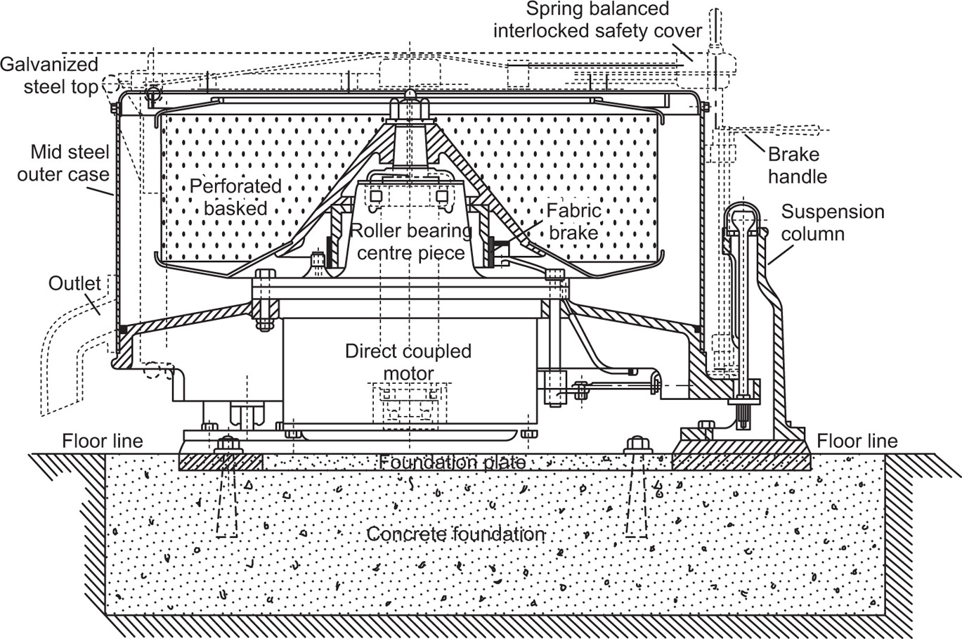
Centrifuging provides a convenient method of separating either two immiscible liquids or a solid from a liquid; it finds several applications in drug manufacture where it may be used either as a batch process or continuously. Essentially centrifuge comprises a bowl or ‘basket’ capable of being rotated at high speed; for small batchwise operations, it is mounted vertically whereas larger centrifuges designed for continuous working have their axes horizontal. Apart from the angle of mounting, the main difference in design relates to the ‘basket’ itself. For the separation of crystals from mother liquor, it is perforated and lined with filter cloth. Spinning forces the liquid through the cloth and leaves a cake of crystals on the inner surface of the basket. The alternative design is a nonperforated basket, and this may be used for separating solid–liquid or liquid–liquid systems. With the former, spinning causes the solid to build up on the walls of the bowl while the liquid is removed through an overflow. For the latter, the effect is to create an outer layer of the denser liquid and an inner layer of the lighter; separate overflow points can be arranged so as to remove the components continuously.
Theoretical Considerations
The force acting upon a particle compels it to move in a circular path around an axis which is given by the
Eq. 17.1:
 (17.1)
where F is centrifugal force, M is the mass of the particle, R the radius of curvature, ω the angular velocity and v the peripheral velocity. It can be seen that for any given peripheral velocity, the force varies inversely as the radius of curvature. The equation gives the total centrifugal force due to the mass of the rotating body and has to be taken into account in the design of centrifuges, so that the centrifuge basket is not subjected to excessive strains. In comparing relative performances of centrifuges, it is useful to express the centrifugal force as a relative force. The relative centrifugal force (RCF) or centrifugal effect is defined as the ratio of centrifugal force to gravitational force acting upon a given body. Thus:
 (17.2)
A more practical form of the equation can be derived in which the centrifugal effect is related to the rate of revolution. Thus,
 (17.3)
where R is radius in cm and N the velocity inrev/min.
The main method of increasing the RCF is to increase the speed of operation but a limit is set upon the peripheral velocity by the maximum safe strain in the basket wall. Increasing its thickness above a certain amount, in order to get additional strength, does not help because it adds to the weight and increases the strain. For the same peripheral velocity, a larger centrifugal effect is obtained with a smaller basket (see
Eqs. 17.1 and
17.2).
The rate of settling, V, of a particle diameter D, at a given distance from the axis of rotation, may be calculated from Stokes’ Law (see p. 149) in which g has been substituted by Rω2.
Thus,
 (17.4)
where
ρ1 and
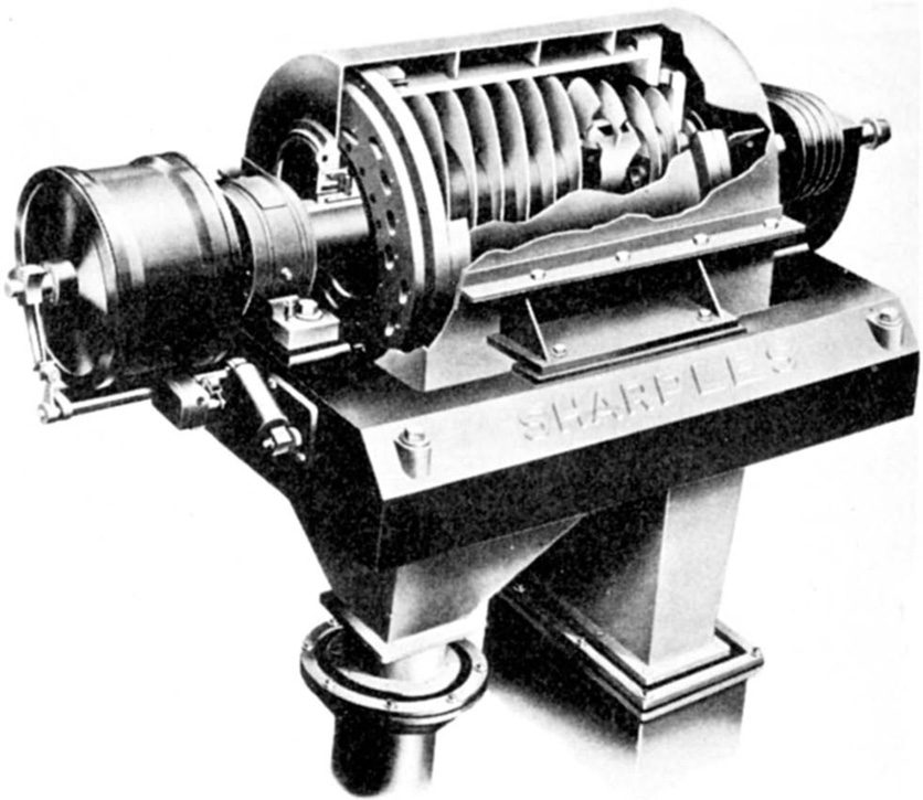
ρ2 are densities of the solid and liquid respectively; η is the dynamic viscosity of the liquid. When using a continuous type centrifuge of the solid basket type such as the Sharples, the rate of flow of the feed must be considered in relation to the rate of settling of the particle. The simplest form of this type of centrifuge can be considered to be a rotating cylinder through which the feed material is passed. If the liquid lies in such a bowl in a thin layer of thickness
S, and is fed continuously at one end and discharged at the other, the time
t, during which the liquid is in the bowl is
X/Q, where
X is the volume of liquid in the bowl at a given time and
Q is the rate of flow of liquid through the bowl. If
S is small, then the velocity of the particle will be nearly uniform and the distance
x settled in time
t can be calculated from
Eq. 17.4. Thus:
 (17.5)
Particles at a distance less than
x from the wall will therefore be removed from the liquid. Thus the rate of flow
Q can be calculated in order that particles of the desired size settle out before the liquid leaves the centrifuge. This example only applies to ideal conditions and is given merely as a guide to the correct operation of a continuous centrifuge of the solid basket type.
The critical speed of a centrifuge is that corresponding to the natural period of vibration of the basket. It may be better understood from the following experiment. If a weight is suspended from elastic held in the hand and made to vibrate up and down, it does so at a definite rate, which is the same whatever the amplitude of the vibration. This is the critical speed. If the hand moves up and down slower than this the weight follows, but if the speed of movement is increased the length of the up and down motion of the weight increases, and when the rate approaches that of the natural vibration (or critical speed) of the weight, the motion of the weight becomes so violent that the elastic will be broken. If the speed is increased so quickly that the critical speed is passed before the weight can build up this violent motion, the motion of the weight will be reduced less and less, and when the motion is very rapid the weight will hardly move at all. In a centrifuge, the basket corresponds to the weight, the buffer bearing to the elastic, the out-of-balance weight to the amplitude of vibration of the hand, and the speed of the machine to the rate of vibration of the hand. A centrifuge has a critical speed of vibration which is slower than the running speed; it is therefore important that the full speed is attained quickly, so that the machine does not run long enough at the critical speed to build up vibration and become dangerous.
Conversion Between Times Gravity (×G) and Centrifuge Rotor Speed (RPM)
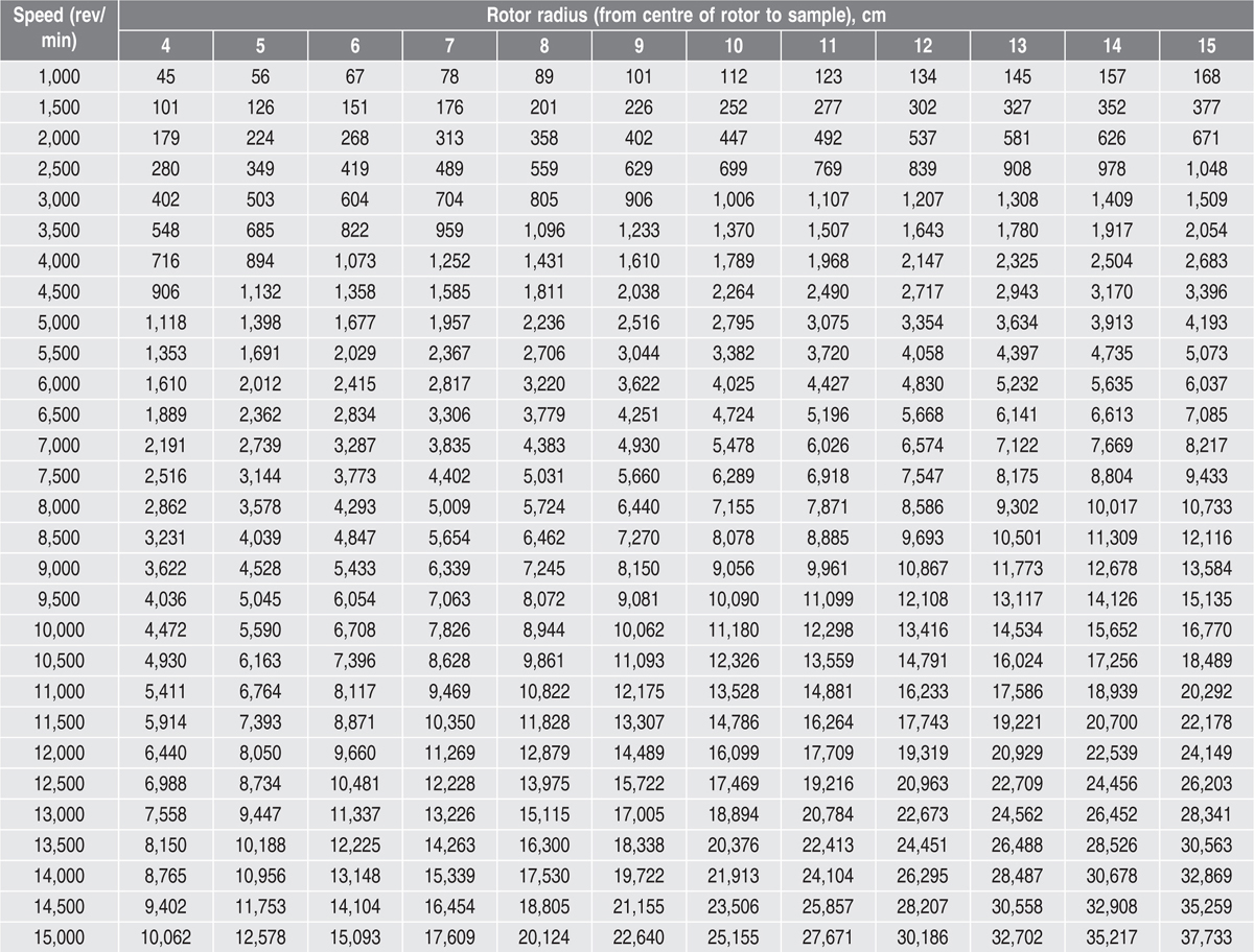
Certain procedures necessitate precise centrifugation conditions, which must be specified in terms of relative centrifugal force (RCF), which is expressed in units of gravity (times gravity or ×g). Many microcentrifuges only have settings for speed (revolutions per minute, rev/min or RPM), not relative centrifugal force. Consequently, a formula for conversion is required to ensure that the appropriate setting is used in an experiment. The relationship between RPM and RCF is as follows:
g = (1.118 × 10⁻⁵)RS2
where
g is the relative centrifugal force,
R the radius of the rotor in centimetres and
S the speed of the centrifuge in rev/ min. Values of RCF in units of times gravity (
×g) for common
microcentrifuge rotor radii appear in
Table 17.1. As an example, centrifugation of a sample at 5000 RPM in a microcentrifuge that has a rotor with a radius of 7
cm will deliver a centrifugal force of 1957
×g. Centrifugation speed and time often are not critical factors in routine sample-handling procedures involving a benchtop microcentrifuge. Usually, as long as speed and time are sufficient to ensure that cells, debris or resin are pelleted effectively, it does not matter if the speed is faster or the time longer than necessary. For this reason, many protocols do not specify a particular centrifugal force to be applied but instead indicate some general guidelines such as ‘centrifuge at high speed for 1 minute’.
Table 17.1 Conversion of RCM to RCF with different radii of rotors
Laboratory Equipment
Centrifuges for laboratory use are generally of the horizontal swinging arm type. The glass tubes holding the liquid are supported in metal buckets which are free swinging from the rotor head. When the rotor revolves, the tubes swing out in a horizontal position so that the particles sediment along the length of the tube. If the centrifuge tubes are held at a fixed angle, about 45–50°C to the vertical axis, both while at rest and while rotating, the sedimenting particles have only a short path to traverse to the sides of the tube. This type of centrifuge is known as the
angle centrifuge and is useful for the rapid sedimentation of particles provided that they do not adhere to the sides of the tube. The RCF obtained in small centrifuges of the types mentioned is about 2000 at approximately 5000 rev/min. In making comparisons between centrifuges, it is, of course, important to specify whether the RCF is measured at the free surface of the liquid or at the tip of the tube. High-speed centrifuges can be used to separate bacteria from aqueous fluids at 10,000
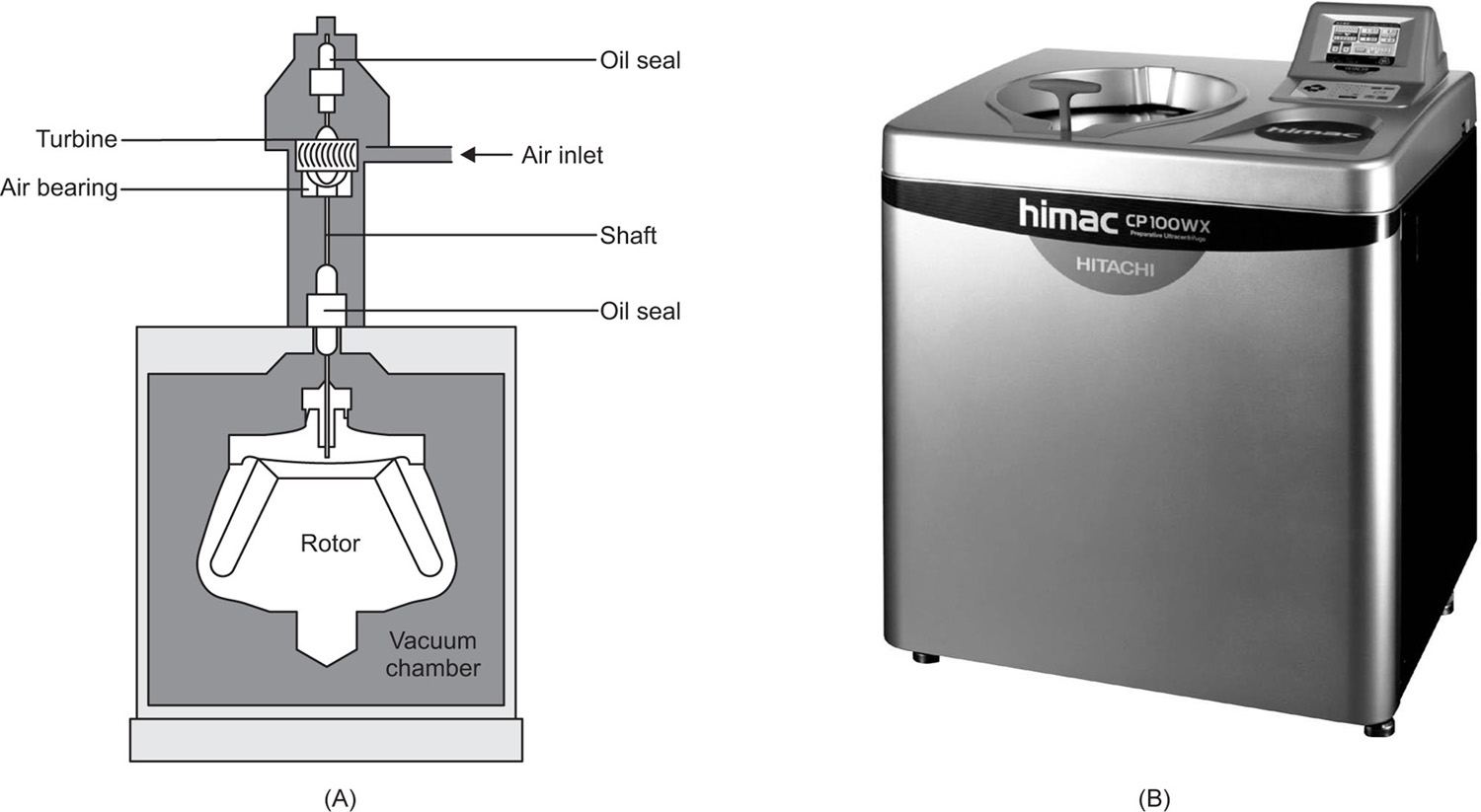
g. The ultracentrifuge which is capable of causing sedimentation of protein molecules may operate at speeds up to 85,000 rev/min resulting in an RCF of up to 2,50,000 (
Fig. 17.1). The size of the rotating head of this type is limited to a few inches in diameter.
High-speed centrifuging is always accompanied by heat generation due to air friction. This can be disregarded for the majority of centrifuging processes but if controlled temperature conditions are required, refrigeration of the centrifuge chamber and operation under vacuum may be necessary.
Zonal Centrifugation
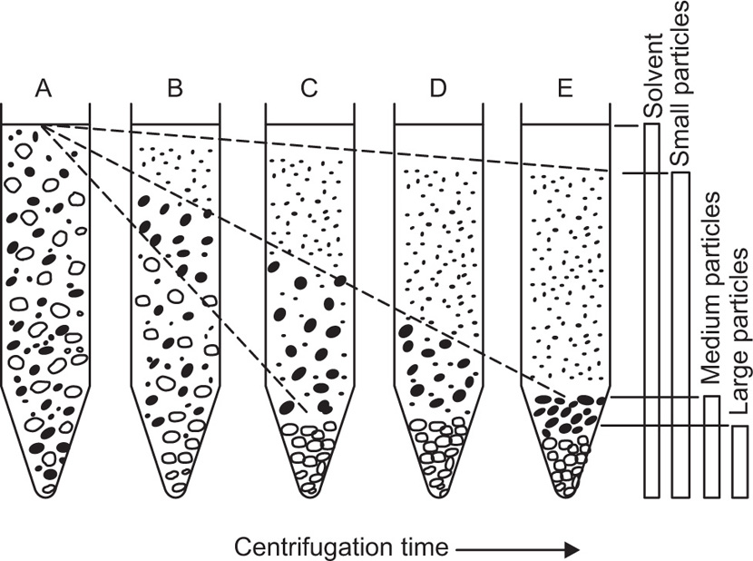
This allows high resolution separation of biological cells and viruses due to the differences in density and size. In an ordinary centrifuge tube, particles in the initially homogeneous suspension settle in the centrifugal field resulting in a distribution of particles of different sizes along the tube (
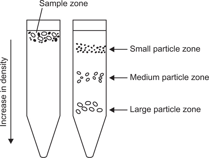
Fig. 17.2). There is no clear-cut separation of particles of different size because the large particles that have settled out will also contain smaller particles that were initially present near the bottom of the tube. Similarly as the intermediate particles sediment they form a layer above the large particles which is contaminated with still smaller particles. By repeated sedimentation fairly clear-cut fractions can be obtained, but generally with considerable loss of material. In zonal centrifugation, the centrifuge tube is filled with a liquid whose density increases towards the bottom and a small sample of particles in suspension is layered over it (
Fig. 17.3). This technique gives zones of sedimenting particles, the rate of movement depending on size and density of the particles.
Zonal centrifuges are designed to eliminate swinging buckets or centrifuge tubes and provision is made for sedimentation to occur in special rotors. The zones are recovered by displacing them by a denser fluid which is pumped into the outer periphery of the rotor while it is rotating at low speed, the stability of the gradient being maintained by centrifugal force. The effluent is then recovered as a series of discrete samples. This technique has been used to separate glycogen particles present in liver cells and the
Supercentrifuge
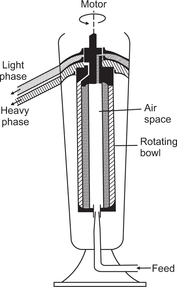
This consists of a relatively long hollow cylindrical bowl of small diameter suspended from a flexible spindle at the top and guided at the bottom by a loose fitting bushing. The speed of rotation is up to 22,000 rev/min with a standard motor drive or up to 50,000 rev/min with an air turbine.
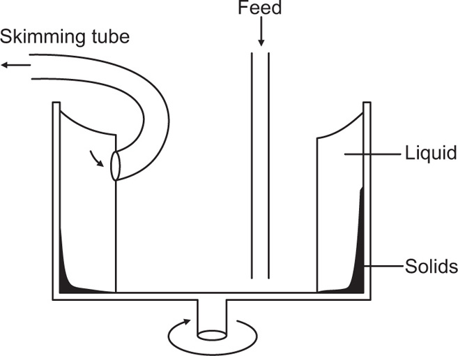
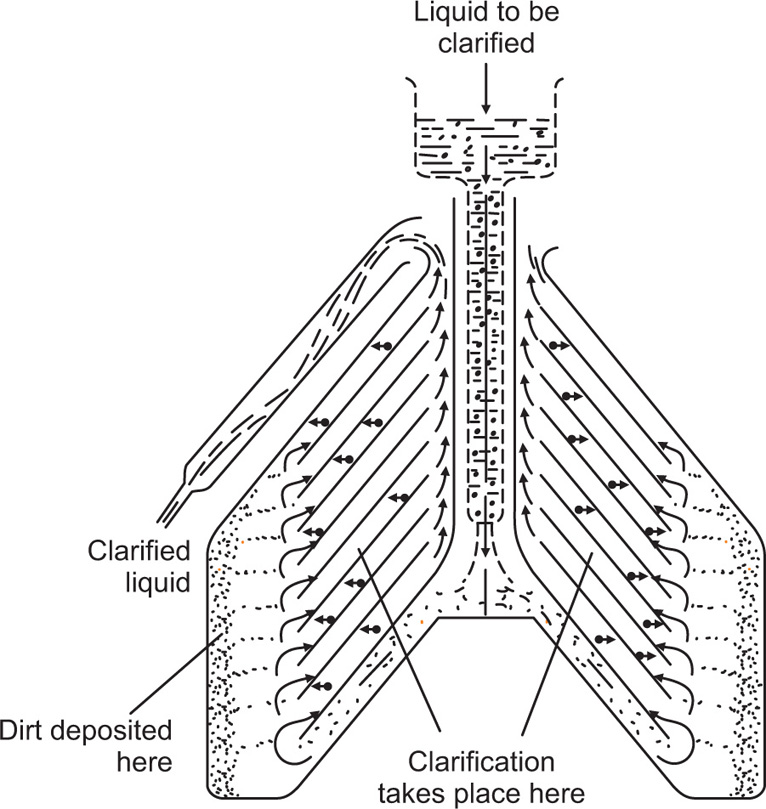
Fig. 17.4 shows the supercentrifuge fitted with a bowl for separating two immiscible liquids. The feed is introduced into the bottom of the bowl by gravity feed and the heavier liquid is thrown out against the wall, with the lighter liquid forming an inner layer. The separated liquids are taken off from the top of the bowl through separate outlets as shown in
Fig. 17.3. For the clarification of liquids the separating bowl is replaced by the clarifier bowl which has one outlet at the top through which the clarified liquid passes, leaving the deposited solids on the wall of the bowl. This centrifuge is limited to the clarification of suspensions of low solid content due to the limited dimensions of the bowl. This restriction does not apply to the separation of liquid–liquid dispersions as there is a continuous take-off of both components.