CHAPTER 124
Orthoses for Mobilization of Joints: Principles and Methods*
ELAINE EWING FESS, MS, OTR, FAOTA, CHT
CRITICAL POINTS
▪ There are no rote solutions for orthotic intervention to combat pathologic conditions of the hand and upper extremity. Orthoses must be created individually to meet the unique needs of each patient.
▪ Mobilization orthoses can be used (1) to correct contractures and increase passive motion, or (2) to substitute for lost active motion, thereby enhancing functional use of the hand.
▪ The expanded American Society of Hand Therapists (ASHT) Splint/Orthosis Classification System/Expanded Splint/Orthosis Classification System (SCS/ESCS) allows consistent and improved communication among medical personnel and elevates the art of orthotic fabrication to a level that supports the advancement of knowledge and improved patient outcomes.
▪ The principles of mobilizing joints through orthotic intervention must be observed to ensure the efficacy of the orthosis.
▪ A hand orthosis requires ongoing reevaluation and adjustment as the target joint(s) improves to ensure that principles of fit are maintained.
Although significant advances have been made in materials and techniques over the decades, the application of external devices to alter upper extremity deformity is not a contemporary concept. One of the earliest descriptions of an orthosis comes from ancient Egypt circa 2750–2625 BCE, and numerous examples are found from the mid-1600s. Surprisingly, the primitive appearance of many of these 15th-century devices belies their relative sophistication of design.1,2 Obvious predecessors to current orthoses, these inventions often provided serial adjustment in tension through mobilizing forces applied with leather strings, chained loops, or metal screws (Fig. 124-1).
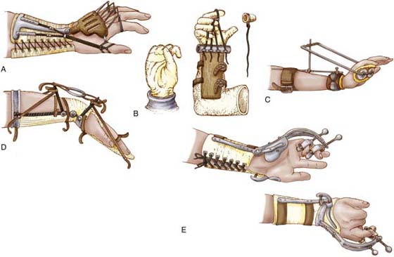
Figure 124-1 A, Wrist extension, index–small finger MCP joint extension, thumb CMC joint radial abduction mobilization orthosis, type 2 (11). B, Index–small finger flexion mobilization orthosis, type 1 (13). C, Wrist extension mobilization orthosis, type 0 (1). D, Wrist extension mobilization orthosis, type 6 (16). E, Wrist extension, ring–small finger MP-PIP joint extension mobilization orthosis, type 0 (5). (Numbers in parentheses indicate number of joints affected by the orthosis.) Orthoses for mobilization of hand–upper extremity joints is not a new concept. These orthoses were described between 1647 and 1927. (From Fess EE. A history of splinting: to understand the present, view the past. J Hand Ther. 2002;15:97-132.)
Today’s thermoplastic materials facilitate the construction and fitting phases of orthosis preparation, but these technologic advancements have not automatically led to better understanding of orthosis design and use. Far too often, an orthosis is exactingly reproduced from a picture without an understanding of the underlying pathologic conditions of the hand and the realistic goals expected of the orthosis. Further, without the application of the principles of mechanics, design, fit, and construction, and without the use of outriggers and mobilization assists that must be applied correctly, effective results cannot be achieved. Unfortunately, any “cookbook” approach to orthotic fabrication is predisposed to ending in frustration, failure, and undue expense and loss of time for the patient. Of paramount importance is the understanding that there are no rote orthotic fabrication solutions to combating pathologic conditions of the hand and upper extremity. Orthoses must be created individually to meet the unique needs of each patient, as evidenced by designs that incorporate the variable factors of anatomy, physiology, kinesiology, pathology, rehabilitation goals, occupation, vocation, and psychological status.
Purposes of Mobilization Orthoses
Mobilization orthoses may be used (1) to correct existing deformity through application of gentle forces that gradually cause collagen realignment and tissue growth, and the concomitant increased passive range of motion (ROM); or (2) to substitute for lost active motion, thereby enhancing functional use of the hand.2
Correction orthoses: If full joint motion is not present, an orthosis is applied to first decrease existing deformity. Orthoses designed to improve passive joint motion are usually temporary and should be constructed of materials that are easily altered, because configuration changes must be made as ROM improves (Fig. 124-2).
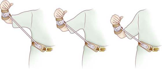
Figure 124-2 Shoulder abduction and external rotation mobilization orthosis, type 3 (4). Shoulder abduction and external rotation may be increased through lengthening of the connector bar. Orthosis design courtesy of McClure and Flowers. (From Fess EE, Gettle KS, Philips CA, Janson, JR. Hand and Upper Extremity Splinting, Principles and Methods. 3rd ed. St Louis: Mosby/Elsevier, 2005.)
Control orthoses: Requiring full passive joint motion, control or substitution orthoses may be fabricated of more durable, less adjustable materials because of their expected protracted time of use. It is essential to clearly understand the differences between these two basic groups of mobilization orthoses. By selecting an inappropriate design option, one may create an orthosis that is ineffective or that actually contributes to the existing pathologic condition. Control or substitution orthoses commonly do not incorporate the types of forces necessary to alter fixed deformity (Fig. 124-3); conversely, correctional orthosis designs may temporarily impede functional use of the hand (Fig. 124-4). Therefore, it is imperative that an orthosis design accurately reflect the purpose for which the orthosis is intended.
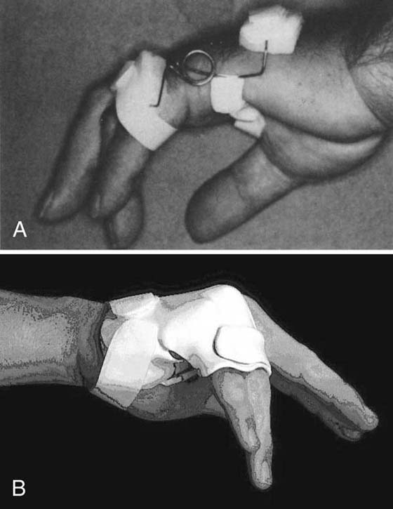
Figure 124-3 Ring–small finger MCP joint extension restriction–IP joint extension torque transmission orthosis, type 0 (6). Requiring passive mobility of joints, these substitution orthoses prevent joint contractures and enhance functional use of the hand in an ulnar nerve injury. (From Fess EE, Gettle KS, Philips CA, Janson JR. Hand and Upper Extremity Splinting, Principles and Methods. 3rd ed. St Louis: Mosby/Elsevier, 2005.)
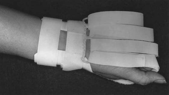
Figure 124-4 Index–small finger flexion mobilization orthosis, type 1 (13). Designed to improve joint motion, this orthosis does not allow functional use of the hand during wearing periods. (From Fess EE, Gettle KS, Philips CA, Janson JR. Hand and Upper Extremity Splinting, Principles and Methods. 3rd ed. St Louis: Mosby/Elsevier, 2005.)
Classification of Mobilization Orthoses
Historically, orthoses have been classified according to purpose of application, configuration, power source, material, or anatomic site. One of the most commonly used classification systems was that of grouping orthoses according to inherent mechanical characteristics, resulting in two major subdivisions. “Static” orthoses had no moving components and were used to provide support and immobilization, whereas “dynamic” orthoses used traction devices such as rubber bands, springs, or cords to apply corrective forces to stiffened joints. With the advancement of experience and knowledge in orthoses, the value of using “static” orthoses to improve ROM through consecutive configuration changes was recognized, and the term “static progressive” orthosis was introduced. Unfortunately, this method of grouping orthoses into three categories is antiquated, and its limitations have become increasingly apparent as clinicians struggle to better define the devices they create.
In 1981, Fess, Gettle, and Strickland3,4 devised a descriptive orthosis classification system based on three criteria: (1) orthosis forces, (2) anatomic site, and (3) kinematic intent. This system described orthoses according to the how, what, and why of design and purpose, grouping similarly functioning orthoses regardless of traction type, material, surface of application, or configuration. This was an important first step toward establishing a true classification system, but it required considerable development and refinement.
American Society of Hand Therapists Splint/Orthosis Classification System and Expanded ASHT Splint/Orthosis Classification System
In 1986 the ASHT conducted a survey of splint/orthosis nomenclature usage among its members and found that considerable differences existed, even in this highly specialized group. To address this problem, a special splint/orthosis Nomenclature Task Force of nationally and internationally recognized hand and upper extremity orthotic fabrication experts was established by the ASHT Board in 1989. This task force was given the charge “to conclusively settle the problems of existing splinting nomenclature.” The result of their work, the ASHT Splint/Orthosis Classification System,5 was published in 1992. Later, in what became known as the Expanded ASHT Splint/Orthosis Classification System, an additional purpose category (torque transmission) and two new descriptors for prostheses and orthosis-prosthesis were identified by Fess, Gettle, Philips, and Janson as they applied the classification system to over 1100 orthosis illustrations included in the 3rd edition of their splinting/orthotic fabrication book that subsequently was published in 2005.2
Both the SCS5 and ESCS2 categorize orthoses according to a series of six descriptive criteria: (1) articular or nonarticular, (2) anatomic focus, (3) kinematic direction, (4) primary purpose, (5) type or number of secondary joint levels, and (6) total number of joints included in an orthosis (Fig. 124-5). These six criteria combine to form a “sentence” that clearly and definitively describes an orthosis. Paralleling grammatical sentence structure, each element of the orthosis “sentence” defines a distinctly separate orthosis element.
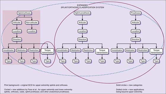
Figure 124-5 An extension of the original ASHT Splint/Orthosis Classification System, the Expanded ASHT Splint/Orthosis Classification System adds an additional purpose category (torque transmission) and allows descriptives for prostheses and splint-prostheses.
For the first criterion, orthoses are considered to be either articular or nonarticular, depending on whether or not they affect joint motion. With the exception of a few specialized, two-point pressure, coaptation orthoses (e.g., fracture braces, pulley orthoses),2 the majority of orthoses operate as three-point pressure systems,2 directly influencing joint motion. Since most orthoses are articular in nature, the designation of articular is assumed for all orthoses in this category. Therefore, the word articular is not included in the SCS/ESCS sentence. In contrast, nonarticular orthoses are always designated as such in an SCS/ESCS sentence (e.g., nonarticular humeral orthosis). All of the orthoses discussed in this chapter fall into the articular category. Articular is assumed rather than specified in their respective SCS/ESCS names.
Anatomy: The primary joints affected by an orthosis are defined by the second of the six descriptors (e.g., shoulder, elbow, forearm; wrist, index, long, ring, small, thumb carpometacarpal [CMC] joint, metacarpophalangeal [MCP] joint, interphalangeal [IP] joint). If all the joints of a segment are considered primary joints, then the segment is named instead of the individual joints involved (e.g., finger, thumb). An example, if all four PIP joints are included as primary joints in an orthosis, the anatomy sentence descriptor would be: Index-small finger PIP joint.
The third criterion, direction, delineates the kinematic course into which the primary joints or segments are moved or positioned (e.g., flexion, extension, radial deviation). Continuing with the above example, if the desired direction is flexion, the SCS/ESCS sentence becomes Index–small finger PIP joint flexion.
Purpose, the fourth criterion, designates whether an orthosis is intended to immobilize, mobilize, or restrict motion,5 or transmit torque to primary joints/segments.2 If the purpose of the above example orthosis is mobilization, then the sentence is expanded to become, Index–small finger PIP joint flexion mobilization orthosis.
The fifth descriptor, type, identifies the number of secondary joint levels included in an orthosis. While the first four criteria are intuitive, type addresses the mechanical function of an orthosis. It is less obvious but no less critical than are the first four criteria. Without type, the classification system falls apart. In defining type, it is important to understand that secondary joints are not named per se, nor are they counted individually. Only the number of secondary-joint longitudinal levels is counted in the orthosis “sentence.” This is in direct contrast to primary joints that are specifically named. Secondary joints often are included to anchor orthoses and/or to control or eliminate undesirable motion of joints other than the primary-focus joints or segments. Secondary joints are not the joints to which corrective forces of an orthosis are aimed. For example, in the previously utilized orthosis example, the wrist and MCP joints may be included to eliminate the wrist tenodesis effect and to stabilize the MCP joints. This allows corrective forces to be directed to the primary PIP joints and eliminates unwanted dissipation of force at the two proximal-joint levels, the wrist level, and MCP joint level. In this example, two secondary joint levels, wrist and MCP joint, are included; therefore the orthosis would be considered a type 2 orthosis. The example orthosis sentence is further expanded to: Index–small finger PIP joint flexion mobilization orthosis, type 2. If no secondary joint levels are included in an orthosis, it is classified as type 0; one secondary joint level is a type 1; three secondary joint levels are type 3, and so on.
The final descriptor, total joint count, is included at the end of the SCS/ESCS sentence in parentheses. This last criterion of the orthosis sentence explicitly counts the number of joints affected by the orthosis. Contrary to type where only the joint levels are counted, all primary and secondary joints are tallied individually in the total joint count number. In the above orthosis example, there are four primary joints, the PIP joints; and there are five secondary joints, the wrist and four MCP joints, for a total count of nine joints. The number 9 is included at the end of the sentence in parentheses. The finished orthosis sentence reads: Index–small finger PIP joint flexion mobilization orthosis, type 2 (9)66.
While many orthosis designs and configurations may fit the orthosis sentence mentioned above, all will function in the same manner. Note that it makes no difference in the SCS/ESCS if an orthosis is applied volarly, dorsally, or laterally, or from what material it is constructed, because design options such as surface of application or material do not influence the intent/function of the orthosis. If it is absolutely critical to convey design options, these specifications may be added at the end of the sentence following a colon. The above example might then read, Index–small finger PIP joint flexion mobilization orthosis, type 2 (9): elastic traction, or if surface of application is vital to communication, the sentence may be written as Index–small finger PIP joint flexion mobilization orthosis, type 2 (9): volar application.
Another example, if the colloquial term “wrist cock-up” is used in a referral, confusion may ensue. Is the orthosis’s purpose to immobilize, to mobilize, or to restrict wrist motion or is it intended to transmit torque to digital joints? One can only guess. In contrast, using the SCS/ESCS, a “wrist cock-up” may be more scientifically described as:
(A) Wrist extension immobilization orthosis, type 0 (1);
(B) Wrist extension mobilization orthosis, type 0 (1);
(C) Wrist flexion restriction orthosis, type 0 (1);
(D) If its purpose is to transmit torque to the fingers as in an “exercise” orthosis, it is an Index–small finger extension and flexion torque transmission orthosis, type 1 (13).
In A through C above, the wrist is the primary joint and no secondary joint levels (type) are included in the orthosis. However, in D, the wrist is the secondary joint and the finger joints are primary joints, although they (finger joints) are not included within the physical boundaries of the orthosis. Compare the total joint count for orthoses A through D. It immediately becomes apparent that D is a very different functioning orthosis from A through C; further, A through C differ in function from each other. Note, not one design option is included in A–D, and yet the essential facts about these orthoses are known. It is even possible to speculate associated diagnoses for these orthoses, an impossibility when confronted with the ubiquitous “wrist cock-up” moniker.
A final example, the extension portion of an MCP joint arthroplasty orthosis, is classified as an Index–small MCP joint extension and radial deviation mobilization orthosis, type 1. The wrist is included as a secondary joint, while the MCP joints are primary joints. Although many different orthosis designs fit into this classification, they all function in the same manner.
As noted at the beginning of this section, many earlier classification methods broke down when required to describe “static” orthoses that were applied serially to correct joint deformity. With the SCS/ESCS method of grouping, orthoses are not categorized according to properties of their components but rather according to intent of application. A serial cast applied to extend the ring finger PIP joint is classified as a Ring finger PIP joint extension mobilization orthosis, type 0 (1). The archaic and limited descriptors “static,” “dynamic,” and “static-progressive” are not used in the SCS/ESCS.
While the ramifications of using an accurate orthosis classification are readily apparent in the above examples, the positive consequences of exactingly describing orthoses are not restricted to clinical applications. In research, the SCS/ESCS allows orthoses with identical functions but different designs to be compared in clinical trials. For example, elastic and inelastic traction design options may be compared in orthoses with the same classification. Language is the key to professional evolution. The more defined splint/orthotic language is, the better the potential becomes for advancing knowledge and improving patient outcomes.
The power of the SCS/ESCS lies in the fact that communication among medical personnel is vastly improved through definition of the important functional aspects of orthoses and through elimination of the confusion caused by colloquial or regional orthosis jargon. Design options such as type of traction (elastic, inelastic), surface of application, material, and outrigger configuration are deemphasized and left to the expert judgment and creativity of those who fabricate orthoses. Use of the SCS/ESCS is an important element to firmly elevating the art of orthotic intervention to a solid science foundation by requiring those who fabricate orthoses to fully understand the intricacies of orthosis function and by discouraging cookbook approaches. Through its inherent characteristics that require in-depth knowledge of anatomy, kinesiology, physiology, and pathology, the SCS/ESCS transitions those who use the system from a technical to a professional echelon.
Assessment
Assessment provides a foundation for orthotic intervention programs by delineating baseline factors from which orthoses can be individually created and progress can be monitored. The evaluation process involves gathering and integrating information derived from many sources. A finished orthosis should not only reflect anatomic, kinesiologic, physiologic, and pathologic requirements but it also should meet the patient’s psychological and socioeconomic needs. Astute observation, detailed interviews, careful inspection, and concise measurement guide the upper extremity specialist in creating orthosis designs that are uniquely adapted to meet specific requirements.
Using instruments proven to be reliable and valid, measurements of extremity mass, temperature, ROM, strength, sensibility, and dexterity provide concrete numeric data about given components of hand function. These measurements are essential to establishing and monitoring orthotic intervention and exercise programs. Often exhibiting rapid change, a healing hand/upper extremity must be constantly and carefully monitored so that the therapist can direct appropriate and efficient adaptation of orthoses and exercises.
Physiologic Factors
Orthotic intervention is one of the most effective means of improving passive mobility of stiffened joints (Figs. 124-6 and 124-7). When used appropriately, orthoses produce gradual rearrangement or lengthening of the pericapsular structures and an elongation of adhesions through directed gentle traction. Therefore, it is important to thoroughly understand the stages of wound healing and how they apply to specific tissues. The careful integration of these concepts into orthoses and exercise programs provides the foundation on which efficacious therapeutic intervention is based. Dictated by the rate of healing and the method of repair of healing tissues after injury, orthotic programs must be designed to judiciously use and manipulate the physiologic process of collagen formation.2-4
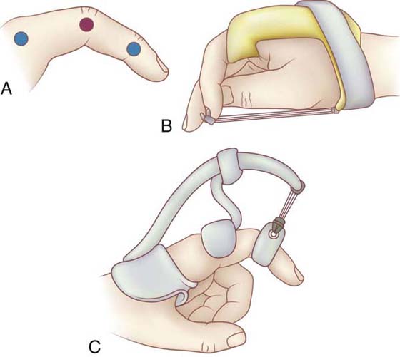
Figure 124-6 Directing mobilization forces to problematic joints is technically more difficult when normal or less stiff joints are situated proximally and/or distally (A, blue dots) to the more stiff joint(s) (A, red dot) for which an orthosis is applied. B, Index finger IP joint flexion mobilization orthosis, type 1 (3). C, Index finger PIP joint extension mobilization orthosis, type 1 (2). Although B and C have different kinematic directions, the two orthoses function mechanically in a similar manner. To prevent dissipation of the PIP joint mobilization force, both orthoses control position of the proximal, normal MCP joint, preventing MCP joint flexion and MCP joint extension, respectively. (From Fess EE, Gettle KS, Philips CA, Janson JR. Hand and Upper Extremity Splinting, Principles and Methods. 3rd ed. St Louis: Mosby/Elsevier, 2005.)
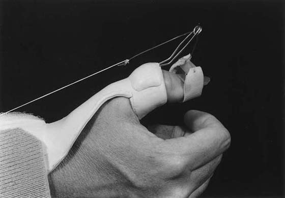
Figure 124-7 Thumb IP joint extension mobilization orthosis, type 3 (4). This orthosis controls secondary joint level (wrist, and thumb CMC and MCP joints) positions while providing a mobilization force to the thumb IP joint. (From Fess EE, Gettle KS, Philips CA, Janson JR. Hand and Upper Extremity Splinting, Principles and Methods. 3rd ed. St Louis: Mosby/Elsevier, 2005.)
The evidence for soft tissue remodeling may be found in research regarding cellular response to mechanical tension-stress.1 Beginning in the late 1940s, Paul W. Brand recognized the importance of tissue remodeling and as a researcher and educator, he continued to emphasize this concept to the hand/upper extremity rehabilitation community.6 While the subspecialty of plastic surgery is especially attuned to this arena because of its involvement in tissue expansion endeavors, other specialty areas are also investigating the biochemical elements of tissue growth. When tension-stress is applied to soft tissues in the form of an orthosis or tissue expander, changes occur in the collagen network alignment. Two types of tissue deformation exist. Mechanical creep (stretch) involves a temporary longitudinal reorganization of collagen from its relaxed random pattern to a parallel pattern in the direction of the applied tension-stress. Once the fibers are parallel, no additional change in tissue length occurs without creating microscopic tissue tearing. A simple analogy is pulling fabric on its bias to its elastic limit. The fabric elongates to a certain length and if the limit of the fabric bias is exceeded, the fabric tears. In contrast, biological creep involves generation of new tissue through mitotic activity—that is, tissue growth.
When tension-stress is applied to living tissue over a prolonged period of time, a cascade of biochemical actions gives rise to biologic creep (tissue growth), including but not limited to generation of growth factors, cytoskeletal structures, and protein kinases. Though not fully understood, changes that occur at the cellular level involve the following events: Cell attachment to the matrix decreases, membrane ruffling occurs, extracellular collagen is produced, sensitivity to insulin increases, growth factors are generated, ion channels are stimulated, and signaling molecules induce the cell nucleus to divide. Cells strive for equilibrium (Fig. 124-8),7 and both amplitude and duration are critical to the outcome of application of tension-stress. Gentle tension-stress over a protracted time creates cell proliferation (Fig. 124-9). Conversely, forceful stretch over a short period of time leads to cell damage, increased inflammatory response, and increased scar formation.
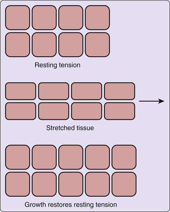
Figure 124-8 Mechanical tension-stress stimulus initiates the tissue remodeling process. (From Fess EE, Gettle KS, Philips CA, Janson JR. Hand and Upper Extremity Splinting, Principles and Methods. 3rd ed. St Louis: Mosby/Elsevier, 2005; originally from De Filippo RE, Atala A. Stretch and growth: the molecular and physiologic influences of tissue expansion, Plast Reconstr Surg. 2002;109:2450–2462; adapted from http://www.plasticsurgery.org.)
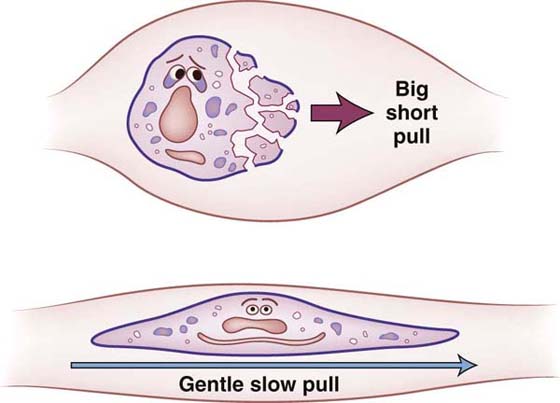
Figure 124-9 Too much force over too little time creates tearing of soft tissues, resulting in increased inflammatory response and additional scar formation. (From Fess EE, Gettle KS, Philips CA, Janson JR. Hand and Upper Extremity Splinting, Principles and Methods. 3rd ed. St Louis: Mosby/Elsevier, 2005.)
Principles of Using Mobilization Orthoses
Basic rules apply to all phases of orthosis preparation regardless of the purpose of application and ultimate orthotic configuration.2-4 These principles define fundamental elements that contribute to the creation of an effectively working orthosis that is comfortable, durable, and cosmetically acceptable, and that successfully meets individual patient requirements. Failure to incorporate these principles may result in orthoses that are eventually discarded, because they are uncomfortable and ineffective or, worse, orthoses that, if worn, cause additional damage to the hand through pressure sores, attenuation of ligaments, compression or distraction of joint surfaces, or inappropriate application of force direction or magnitude to healing structures. The decision to apply mobilizing forces to an injured or diseased hand is a serious consideration; it should involve close communication between the physician, the therapist, and the patient. Further, it is important that the goals of orthosis application be realistic and that all those involved thoroughly understand and accept the responsibilities of such an endeavor.
Mechanical Principles
Because orthotic intervention consists of external application of forces to the extremity, an understanding of basic mechanical engineering concepts is an essential prerequisite to the design, construction, and fitting of all hand orthoses. Pressure from the orthosis on the extremity can be controlled or diminished by widening the area of force application and by increasing the mechanical advantage of lever systems. Clinically, this means that orthoses that are longer and wider are more comfortable, and a contiguous fit of narrow components over bony prominences is of paramount importance (Fig. 124-10).
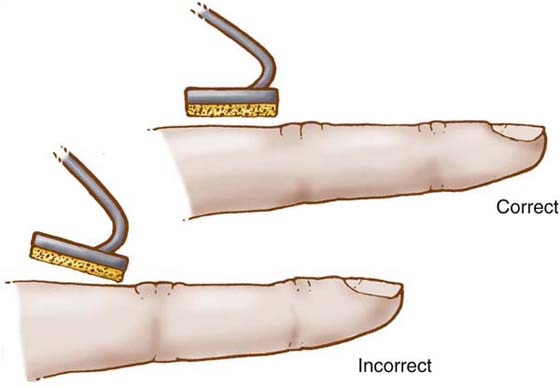
Figure 124-10 To reduce pressure, narrow orthosis components should be fitted carefully to achieve contiguous contact between orthosis part and hand. (From Fess EE, Gettle KS, Philips CA, Janson JR. Hand and Upper Extremity Splinting, Principles and Methods. 3rd ed. St Louis: Mosby/Elsevier, 2005.)
Elimination of the translational component of an applied force by maintaining a 90-degree angle of approach to the segment being mobilized (Fig. 124-11) is also of utmost importance when designing and fitting orthoses. This allows the full magnitude of the rotational force to be directed toward correcting the joint deformity and excludes force components that cause compression or distraction of the articular surfaces. In addition, understanding of torque and the integrated effects of reciprocal parallel forces allows identification and control of the magnitude of corrective and stabilizing forces as they relate to the placement of specialized orthosis parts. The relative degree of passive mobility of successive joints also plays an important role in orthosis design. If mobilizing forces are dissipated at normal or less involved joints, the potential for increasing passive motion of stiff joints within the same longitudinal segment is diminished considerably. Therefore, mobilization orthoses must be designed to apply corrective forces to only those joints that lack passive motion (Fig. 124-12).
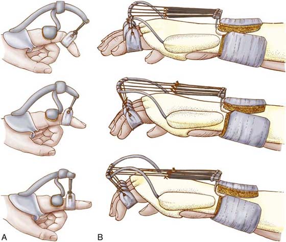
Figure 124-11 A 90-degree angle of the dynamic assist to the mobilized segment must be maintained as passive joint motion changes. A, High profile. B, Low profile. (From Fess EE, Gettle KS, Philips CA, Janson JR. Hand and Upper Extremity Splinting, Principles and Methods. 3rd ed. St Louis: Mosby/Elsevier, 2005.)
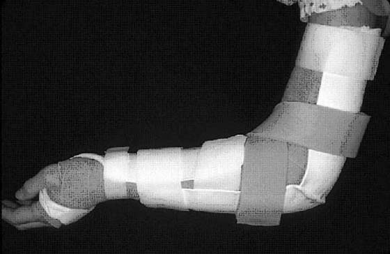
Figure 124-12 Forearm supination or pronation mobilization orthosis, type 2 (3). Incorporation of the elbow and wrist as secondary joints, focuses mobilization forces on the forearm. (Orthosis design courtesy Paul Van Lede, OT, MS, Orfit Industries, Wijnegem, Belgium. From Fess EE, Gettle KS, Philips CA, Janson JR. Hand and Upper Extremity Splinting, Principles and Methods. 3rd ed. St Louis: Mosby/Elsevier, 2005.)
Excessive shear stress leads to tissue breakdown and ulceration. Understanding the effects of shear on soft tissue is also imperative to successfully designing, constructing, and fitting orthoses. High-shear effects may be avoided by rounding orthosis edges, by keeping pressures low, and by eliminating unwarranted motion and friction. Finally, for a more effective method of increasing orthosis durability than the retrospective trussing of layers of plastic, orthotic material strength may be increased by designing contour into the orthosis. Mechanical principles determine orthosis effectiveness, comfort, and durability, and should be carefully incorporated into the design, construction, and fitting phases of orthosis preparation.
Principles of Using Outriggers and Mobilization Assists
Regardless of their external configuration, orthoses that are designed either to improve motion of stiff joints or to substitute for loss of active motion must have a means of generating and directing forces. Depending on the purpose of orthosis application, these forces either apply prolonged gentle pull to influence collagen alignment of stiffened joints or move passively supple joints to enhance hand function.
The two key words associated with application of force to mobilize stiffened joints are prolonged and gentle. Orthoses designed to improve passive ROM must be worn for sufficient time to allow collagen realignment and tissue growth to occur. Wearing an orthosis for 1 or 2 hours a day is insufficient time for tissue growth to take place. For example, it would not be unusual for a patient to be instructed to wear his orthosis continuously except for exercise sessions when the orthosis is removed for 10 minutes of exercise, every 2 or 3 hours throughout the day. Wearing schedules must of course be modified to meet the specific requirements of each situation, but the concept of the application of traction over a long period of time is fundamental. The second word, gentle, is of equal importance. Forces that are too great cause further injury to soft tissue structures, resulting in pain, increased inflammatory response, and additional scar formation. The devastating and debilitating cyclic pattern of forceful traction (through orthotic intervention or manipulation), tissue injury, pain, inflammation, and production of additional scar must be avoided at all costs.
When mobilization assists are used to apply traction to stiff joints, identification, control, and maintenance of force magnitude are critical. Generally speaking, forces between 100 and 300 g are thought to be acceptable to generate tissue remodeling of the small joints of the hand. It has been shown that experienced hand therapists adapt the amount of pull within this range to accommodate variations in diagnosis and physiologic timing.2
Actual measurement of force magnitude for substitution or control orthoses is not necessary, because the joints being moved are supple and the required force is that which is sufficient to move the segments into a desired posture.
The range of forces generated by a mobilization assist depends on inherent physical properties of its base material and on the specific design of the assist. Forces created by rubber bands depend on thickness, length, and quality of rubber; springs rely on gauge, tensile strength, and diameter and length of coils. Shelf-life also influences some mobilization-assist materials. The physical properties of a mobilization assist should be correlated with patient requirements and with orthosis design. For example, an assist that requires frequent adjustment would not be an appropriate choice for a patient who has difficulty returning to the clinic, and an assist that depends on considerable length to provide consistent tension would be inappropriate for a hand-based orthosis design.
Independent studies by Gyovai and Howell,8 Boozer et al.,9 and van Velze and Farmer10 show that not only must one know the force magnitude of the mobilization assist used on an orthosis, one also must understand that a frictional component exists between the interface material of the mobilization assist and the outrigger fulcrum in all low-profile outrigger designs. This friction component affects the force required to bring the positioned segment into position for substitution orthoses or the magnitude of corrective force applied to a stiff joint, as well as the active opposing finger forces required to overcome the pull of the mobilization assist. A simple formula may be used to define the effects of this friction. For example, if A is the force required to effect tissue growth at a stiff joint, and B is the amount of friction between the outrigger and the mobilization assist interface, then A + B = C, where C is the total amount of pull the mobilization assist (rubber band or spring) must generate to overcome the frictional component and apply A amount of corrective force to the joint. Because C will always be greater than A due to the added frictional component B, muscle strength to oppose the force of C must be greater than C. Clinically, this means that patients fitted with low-profile outrigger design orthoses will need greater muscle strength than would those patients fitted with high-profile outriggers where friction between the outrigger and the mobilization assist is nonexistent. High-profile outrigger designs have only the force of the mobilization assist A to consider. If weakness opposite to orthosis pull is an important patient factor, a high-profile outrigger design is preferable.
Mechanical and fit principles also must be applied in conjunction with principles of using mobilization assists. A mobilization assist should apply force in a direction that is 90 degrees to the segment being mobilized and perpendicular to the axis of joint rotation. Pressure on attachment devices such as finger cuffs and nail hooks should be monitored carefully and maintained at minimum levels, and friction and shear should be avoided.
Design Principles
The principles of design may be divided into two basic groups: general considerations and specific considerations. General principles incorporate broad concepts that result in an orthosis that is practical for both the patient and the therapist, while the more specific guidelines are concerned with the unique pathologic conditions exhibited by individual patients. Factors such as age, ability to accept responsibility, independence, and occupational demands contribute to the overall design of an orthosis, as do anticipated use time and prescribed exercise regimens. Orthoses should allow maximum function and sensation and should be as simple in design and appearance as possible. Construction time also should be within reason. Specific principles of design individualize orthoses to the existing requirements of pathology, anatomy, physiology, and kinesiology. Clinicians must consider the following questions: Is the orthosis intended to substitute for absent active motion, or is it designed to correct existing deformity? Will elastic or inelastic forces be more effective? What orthosis components are required to control which joints, and what type of mobilizing forces will provide the greatest potential for increasing passive and concomitant active motion of stiff joints? Which mechanical principles should be used to increase effectiveness, comfort, and durability? These and many other questions must be anticipated and answered before design concepts reach the finality of pattern construction.
Component designing lends an organized and rational approach to creating orthoses that meet individual patient needs. Problems are identified and orthosis parts are mentally assembled to control or diminish the projected pathologic situation. This approach requires that the designer be fully cognizant of the uses and ramifications of each orthosis component. For example, low-profile outriggers have been shown to lose adjustment more quickly than do high-profile outriggers (Fig. 124-13). However, this is a potential problem only if one is dealing with correctional forces. If the purpose of an orthosis is to substitute for active motion, full passive joint motion is a prerequisite and the need for sequential adjustments to accommodate motion improvements is nonexistent. Low-profile outriggers are appropriate design options for control or substitution orthoses, because sequential adjustments are not needed. Conversely, high-profile outriggers provide longer increments of near 90-degree angle of pull than do the low-profile designs, indicating that for correctional orthoses the higher design option will require fewer adjustments as improvements in motion are gained. Whether this is an important concept in the designing of a correctional orthosis entirely depends on the patient’s capacity to return to the clinic for adjustments, expenses incurred for adjustments, and the time demands of the therapist’s caseload.
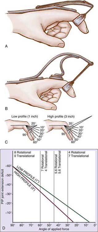
Figure 124-13 Schematic representation of low-profile outrigger (A) and high-profile outrigger (B). Comparison of low- and high-profile outriggers indicates that as passive motion improves, the high-profile design maintains a better angle of pull without adjustment than does the low-profile design (C and D).
Orthosis designing should never be approached in a rote or routine manner. Although patients may have similar diagnoses, the pathologic conditions presented are unique, as are the patient’s intellectual and emotional capacities to deal with injury and dysfunction. Therapists must approach each case anew to attain maximum rehabilitation potential, using orthoses designed efficaciously, realistically, and practically for all involved.
Construction Principles
Observing proper construction principles and selecting equipment and methods appropriate to the materials used will help ensure the durability, cosmesis, comfort, and usefulness of the finished orthosis. Orthosis corners should be uniformly rounded, edges smoothed, joined surfaces stabilized, rivets finished, and straps and padding secured. Mechanical principles should be analyzed and incorporated to enhance durability and comfort, and careful adherence to safety precautions when working with orthotic fabricating equipment is important. The equipment and the type and temperature of heat should be selected to meet the demands of the orthotic material used. Failure to adhere to construction guidelines may result in orthosis disuse because of patient discomfort, lack of acceptance, or orthosis breakage from mechanical failures, all of which represent loss of time and needless expense for both the patient and the members of the rehabilitation team.
Principles of Fit
Fitting principles may be divided into four groups: (1) mechanical, (2) anatomic, (3) kinesiologic, and (4) technical. Mechanical factors include use of forces that are perpendicular both to the bone being mobilized (bone angle of rotation; BAR)2 and to the axis of joint angle rotation (JAR).2 When traction is applied simultaneously to several joints within a digit, care must be taken to ensure that the pull is perpendicular to the rotational axis of each joint. In addition, pressure reduction through contiguous fit and application of lever systems in fitting orthosis components is important. Anatomic factors encompass the use of skin creases as guidelines for orthosis boundaries, identification and adaptation to bony prominences, support of longitudinal and transverse arches, understanding of ligamentous stress, and proper alignment of orthosis and anatomic joint axes. A hand in motion presents a multiplicity of differing external configurations and internal muscle dynamics as it moves through various planes. Kinesiologic considerations, which include kinematic and kinetic principles, are very important to orthosis design and fitting phases. Orthosis parts must be fitted to allow motion, and they must be placed appropriately to control or augment motion, depending on individual requirements. Technical considerations emphasize efficiency and include developing patient rapport, developing work skills, and adapting methods to the materials used. An orthosis must be reevaluated continually to ensure a proper fit. As the hand heals and motion improves, the therapist must recognize changes that occur, incorporating appropriate adaptations into the orthosis as needed. Failure to do so will invariably render the orthosis less effective, impeding the advancement of the rehabilitation process.
Conclusion
Mobilization orthoses play an important role in the rehabilitation process of the diseased or injured hand. Providing correctional or substitutional forces, mobilization orthoses are designed and fitted according to specific requirements unique to each patient. Orthotic intervention programs also must be augmented with appropriate exercise routines and activities that encourage functional use of the extremity. Orthoses alone do not produce the active motion necessary for hand use. It is the astute combination of passive motion, provided through orthotic endeavors, and active exercise programs aligned with patient occupational and vocational needs that forms the foundation for hand rehabilitation techniques, allowing the patient to return to a productive life.
REFERENCES
1. Fess EE. A history of splinting: to understand the present, view the past. J Hand Ther. 2002;15(2):97–132.
2. Fess EE, Gettle K, Philips C, Janson R. Hand and Upper Extremity Splinting: Principles and Methods. 3rd ed St. Louis: Mosby; 2005.
3. Fess EE, Gettle KH, Strickland JW. Hand Splinting Principles and Methods. St. Louis: Mosby; 1981.
4. Fess EE, Philips CA. Hand Splinting Principles and Methods. 2nd ed St. Louis: Mosby; 1987.
5. American Society of Hand Therapists, A. Splint Classification System. Chicago: The Society; 1992.
6. Brand PW, Hollister A. Clinical mechanics of the hand. 3rd ed St. Louis: C. V. Mosby Co; 1999.
7. De Fillipo RE, Atala A. Stretch and growth: the molecular and physiologic influences of tissue expansion. Plast Reconstr Surg. 2002;109(7):2450–2462.
8. Gyovai J, Howell J. Validation of spring forces applied in dynamic outrigger splinting. J Hand Ther. 1992;5:8–15.
9. Boozer JA, Sanson MS, Soutas-Little RW, et al. Comparison of the biomedical motions and forces involved in high-profile versus low-profile dynamic splinting. J Hand Ther. 1994;7(3):171–182.
10. van Velze C, Farmer H. Low-profile dynamic splints: a solution to the friction problem. J Hand Ther. 1993;6(4):308–312.
