Chapter 15 Catheter-Based Peripheral Angiography
Catheter-based invasive contrast angiography is the standard method for diagnosing peripheral artery disease (PAD), and against which all other methods are compared for accuracy. Angiography provides the “road map” on which therapeutic decisions are based. Knowledge of the vascular anatomy and its normal variations is a core element in the skill set required to safely perform peripheral vascular angiography and intervention.
Imaging Equipment
There are many radiographic equipment vendors and many different room layout schemes suitable for performing peripheral vascular angiography. However, if both cardiac and noncardiac types of peripheral vascular angiography are to be performed in the same room, equipment options become much more limited. One angiographic suite designed to perform both coronary and peripheral vascular angiography is a dual-plane system (Fig. 15-1). A dual-plane system encompasses a layout with two independent C-arm image intensifiers operated by a single x-ray generator and one computer. A dual-plane system is not synonymous with a biplane system, which is the simultaneous operation of an anteroposterior (AP) and lateral (LAT) image acquisition system. In a dual-plane system, the cardiac C-arm is a three-mode flat-panel image intensifier, and the noncardiac C-arm should be as large as possible, usually a 15- or 16-inch flat-panel image intensifier. For peripheral vascular imaging, particularly bilateral lower-extremity runoff angiography, an image intensifier smaller than 15 inches may not be able to include both legs in the same field. The noncardiac C-arm must be capable of head-to-toe digital imaging.
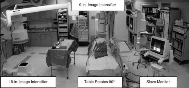
Figure 15-1 Dual-plane catheterization laboratory.
Note two C-arm image intensifiers (9- and 16-inch), with catheterization table able to rotate 90°.
Ability to angulate the image intensifier is necessary to resolve bifurcation lesions and optimally image aorto-ostial branch lesions. Of the many imaging options available, those most often used include digital subtraction angiography (DSA), roadmapping, and a stepping table for lower-extremity (digital subtraction) runoff angiography.
Radiographic Contrast
Ionic low-osmolar or nonionic iodinated radiographic contrast is preferred for angiography of the peripheral vessels to avoid patient discomfort. Low-osmolar contrast agents produce fewer side effects (e.g., nausea, vomiting, local pain) and offer better patient tolerability. In addition, low-osmolar agents deliver a lesser osmotic load and thereby a lower intravascular volume, which may be important in patients with impaired left ventricular or renal function. Digital subtraction angiography is often preferred because nonvascular structures are removed and less contrast is required.
Alternatives to iodine-based radiographic contrast include carbon dioxide (CO2) and gadolinium (gadopentetate dimeglumine).1,2 To minimize the risk of distal embolization and stroke, it is recommended that CO2 not be used for angiograms above the diaphragm.3 Gadolinium, traditionally used with magnetic resonance imaging (MRI), is relatively nontoxic in patients with adequate renal function at a recommended dose not exceeding 0.4 mmol/kg.4
Imaging Technique
Many of the technical aspects of diagnostic cardiac imaging also apply to performing angiography of the aorta and peripheral vasculature. The basic principle of vascular angiography is not only to visualize the target lesion but also demonstrate the inflow and outflow vascular segments. Inflow anatomy constitutes the vascular segment preceding the target lesion, and outflow constitutes the vascular segment immediately distal to the target vessel and includes the runoff bed. For example, the inflow segment for the common iliac artery (CIA) is the infrarenal aorta, and the outflow segment is the external iliac and femoral vessels. The runoff bed would be the tibioperoneal vessels.
When performing selective arterial imaging, it is important for patients’ safety that a coronary manifold with pressure measurement be used to monitor hemodynamic status and ensure that damping of the catheter has not occurred prior to injecting contrast. Use of pressure monitoring during selective angiography can prevent a myriad of complications—including the creation of dissections and air injection.
Angiography may be performed using a “bolus chase” cineangiographic method or with a digital subtraction stepping mode. The bolus chase technique involves injecting a bolus of contrast at the inflow of the territory, then “panning” or manually moving the image intensifier to follow the bolus of contrast through the target lesion and into the run-off segment. In digital subtraction stepping mode, the patient lies motionless on the angiographic table. A “mask” of the segments to be imaged is taken, and then contrast is injected. The table moves in steps to image the contrast-filled vessels, from which the mask is then subtracted, leaving only the contrast-filled vascular structures.
Obtaining Vascular Access
Vascular access for noncardiac diagnostic angiography is most commonly achieved at the common femoral artery (CFA), with alternative upper-extremity sites at the radial, brachial, or axillary artery.5 The most common complications of angiographic procedures occur at vascular access sites.
A thorough understanding of the relationship of the CFA to anatomical landmarks is necessary to ensure safe CFA puncture (Fig. 15-2). The femoral artery and vein lie below the inguinal ligament, which is a band of dense fibrous tissue connecting the anterior superior iliac spine to the pubic tubercle. The inguinal skin crease, which is variable in location, is shown as a dotted line in the figure. Current recommendations are to use fluoroscopic guidance to image the femoral head to guide CFA puncture.6
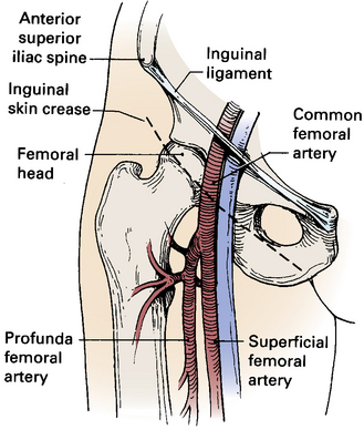
The most important landmark for femoral access is the head of the femur. In a morphological study using CT images, there was not a single case in which a puncture would have passed cranial to the inguinal ligament or caudal to the femoral artery bifurcation if the CFA were entered at the level of the center of the femoral head.7 Caudal to the femoral head, the CFA is encased in the femoral sheath and bifurcates into the superficial femoral artery (SFA) medially and the deep femoral artery (DFA) laterally. With these anatomical observations in mind, the importance of osseous support and entry of the needle into the CFA at the center of the femoral head is obvious.
Anatomical landmarks are initially identified by palpation of the anterior superior iliac spine and pubic tubercle to locate the inguinal ligament; position of the femoral head is confirmed fluoroscopically. Depending on the amount of subcutaneous fat, a skin incision should be made 1 to 2 cm caudal to the level of the center of the femoral head. The needle is directed in an oblique direction while palpating the CFA over the center of the femoral head. Once the CFA has been entered and brisk blood flow returns through the needle, a soft guidewire is advanced into the iliac artery, and a vascular sheath is inserted to secure vascular access.
Complications of CFA puncture are most commonly related to arterial entry that is either too high or too low. When the puncture is too high, a retroperitoneal hemorrhage may occur.8 Presence of loose connective tissue in the retroperitoneal space can lead to large hematomas. Lack of osseous support and presence of a tense inguinal ligament at the arterial puncture site make manual compression difficult. Low punctures may be complicated by formation of arteriovenous fistulas (AVFs), false aneurysms, and hematomas.
Abdominal Aortography and Lower-Extremity Runoff
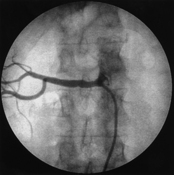
For abdominal aortography, vascular access with a 4 F to 6 F catheter is obtained in the CFA, although brachial or radial access may also be used. The angiographic catheter (e.g., pigtail, tennis racquet, omni flush) is positioned in the abdominal aorta such that the tip of the catheter reaches the level of the last rib. A power injector is used to deliver 20 to 30 mL of contrast at 15 mL/sec for digital subtraction (Fig. 15-3). Either biplane angiography may be obtained or, if needed, two separate angiograms with single-plane systems. Three visceral (mesenteric) arterial branches, the celiac trunk, superior mesenteric artery (SMA), and inferior mesenteric artery (IMA), arise from the anterior surface of the abdominal aorta (Fig. 15-4). The renal arteries originate from the lateral aspect of the abdominal aorta at the level of L1 to L2. The AP projection allows visualization of the aorta, renal arteries, and iliac artery bifurcation, whereas the LAT view demonstrates the origin of the celiac trunk and mesenteric arteries. Commonly in the AP view, the proximal portion of the SMA obscures the origin of the right renal artery. When this occurs, selective angiography of the renal artery may be required to visualize the origin of this vessel.
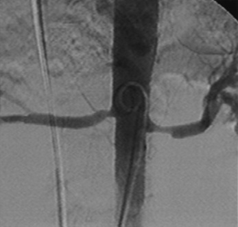
Pigtail catheter contrast injection of 20 mL/sec for 30 mL (5° left anterior oblique [LAO]) using a digital subtraction angiography (DSA) technique. Note bilateral renal artery stenosis.
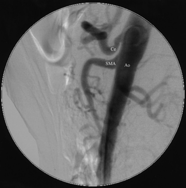
Lateral (LAT) aortogram. Aorta (Ao), with celiac trunk (Ce) and superior mesenteric artery (SMA) arising from anterior aortic surface.
Generally, a nonselective abdominal aortogram is obtained before selective renal angiography, using a large format (9- to 16-inch) image intensifier with digital subtraction imaging. The nonselective aortogram demonstrates the level at which the renal arteries arise, presence of any accessory renal arteries and their location, severity and location of aortoiliac pathology, and presence of significant renal artery stenosis. To optimize viewing of the renal arteries, the angiographic catheter should be placed below the origin of the SMA, and the image intensifier should be positioned such that the superior, inferior, and lateral borders of both kidneys are visualized. The ostia of the renal arteries are often better seen with slight rotation of the image intensifier, usually into left anterior oblique (LAO) position.
Selective Renal Angiography
Selective renal angiography is indicated to identify suspected renovascular disease. Selective renal artery engagement allows measurement of pressure gradients, particularly if ostial lesions are suspected. When measuring pressure gradients across lesions, it is important to use the smallest catheter possible (i.e., ≤4 F) to avoid creating an artificial gradient. The 0.014-inch pressure wire (RADI) is the optimal method of pressure gradient measurement. Usually, selective renal angiography is performed with 4 F to 6 F diagnostic catheters (Fig. 15-5) and a 9-inch image intensifier. Selective renal angiography is performed using hand injections with shallow oblique angulations to optimize visualization of the renal ostia (Figs. 15-6 and 15-7). Caudal or cranial angulation (15° to 20°) may occasionally be necessary for better visualization of some ostial lesions. An optimal image will reveal the ostial portion of the renal artery and distal branches at the cortex of the kidney.
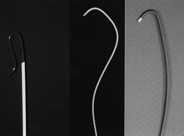
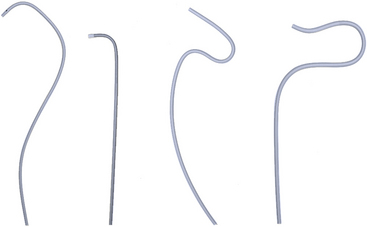
Figure 15-5 Selective renal angiographic catheters.
Left, Sos. Middle, Cobra. Right, Internal mammary artery (IMA) catheter.
Selective Mesenteric Angiography
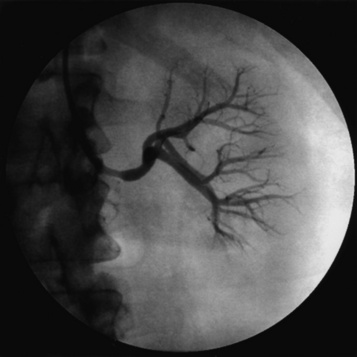
As is the case for the renal arteries, nonselective aortography (AP and LAT) generally precedes selective angiography of the mesenteric arteries. Once the origin of the mesenteric vessel has been identified, selective angiography may be carried out in the LAT and oblique views using 4 F to 6 F catheters (Fig. 15-8). The celiac trunk, SMA, and IMA arteries arise from the anterior surface of the aorta. There commonly are collaterals between the mesenteric vessels, and it is uncommon for stenosis or occlusion of a single branch to cause clinical symptoms.
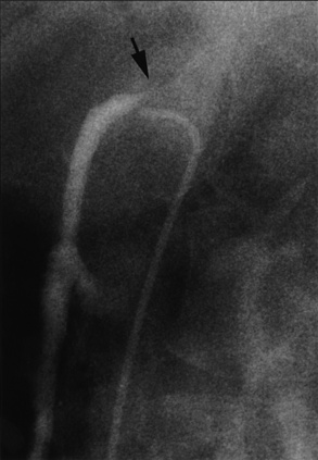
Figure 15-8 Selective superior mesenteric angiography in lateral (LAT) projection, with internal mammary artery (IMA) catheter.
The mesenteric arteries often arise at an inferior (caudal) angle from the abdominal aorta, for which a shepherd’s crook catheter via femoral artery access is helpful for selective engagement. Alternatively, upper-extremity vascular access allows the mesenteric arteries to be engaged with a multipurpose-shaped catheter. Analogous to the renal arteries, selective engagement of the mesenteric arteries also allows measurement of the pressure gradient. Selective angiographic images in multiple views are obtained with hand injections of contrast.
Aortoiliac and Lower-Extremity Angiography
The abdominal aorta bifurcates into the common iliac arteries (CIA), which bifurcate into the internal (IIA) and external (EIA) iliac arteries (Fig. 15-9). The IIA is often referred to as the hypogastric artery because this vessel commonly provides collateral circulation to the viscera. The EIA emerges from the pelvis just posterior to the inguinal ligament. At the level of the inguinal ligament, two small branches originate from the EIA: the inferior epigastric artery, which follows a medial direction, and the deep iliac circumflex artery, which takes a LAT and superior direction.
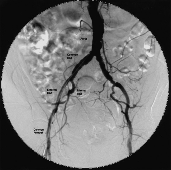
Figure 15-9 Aortoiliac angiography.
Pigtail catheter contrast injection of 20 mL/sec for a total of 30 mL.
On crossing the inguinal ligament, the EIA becomes the CFA, which lies over the femoral head. When it reaches the lower third of the femoral head, the CFA divides into the SFA and profunda femoris, or DFA. The DFA runs posterolaterally along the femur. The SFA continues down the anteromedial thigh, and in its distal portion dives deeper to enter Hunter’s (adductor) canal and emerges as the popliteal artery (Fig. 15-10).
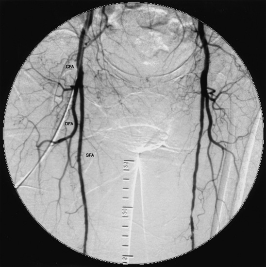
Figure 15-10 Common femoral arteries (CFA) branching into deep femoral artery (DFA) and superficial femoral artery (SFA).
Below the knee, the popliteal artery bifurcates into the anterior tibial (AT) artery and tibioperoneal trunk (TPT). The AT artery runs laterally and anterior to the tibia toward the foot and continues onto the foot as the dorsalis pedis (DP) artery. The TPT bifurcates into the posterior tibial (PT) and peroneal arteries (Fig. 15-11). The PT artery courses posteriorly and medially in the calf, whereas the peroneal artery runs near the fibula between the AT and PT arteries. On the dorsum of the foot, the DP artery has lateral and medial tarsal branches. After the PT artery passes behind the medial malleus, it divides into medial and lateral plantar arteries. The lateral plantar and distal DP arteries join to form the plantar arch.
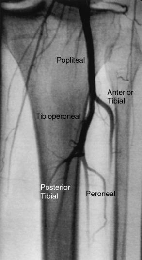
Figure 15-11 Left popliteal artery bifurcates into anterior tibial (lateral) and tibioperoneal trunk, which then divides into posterior tibial (medial) and peroneal arteries.
Vascular access for diagnostic aortoiliac and lower-extremity angiography is obtained in the CFA, preferentially in the least symptomatic extremity, although upper-extremity access (axillary, brachial, or radial) may also be used. A 4 F to 6 F pigtail catheter is positioned above the aortic bifurcation. The preferred technique is to use DSA with a stepping table and a large (15- or 16-inch) format image intensifier so that both legs are imaged together. A single bolus of contrast is injected from the catheter at the aortic bifurcation at 8 to 12 mL/sec for 8 to 10 seconds, and sequential images are obtained from the aorta to the feet.
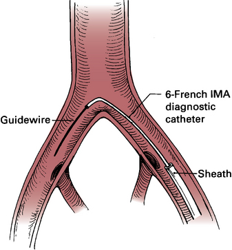
Selective angiograms performed in angulated views of a particular artery or arterial segments are useful when clarification of a potential stenosis is needed. One option is to place a diagnostic catheter at different levels in the iliac, femoral, or popliteal artery for a more detailed examination of a particular arterial segment. If access has been obtained in the CFA and the arterial segment in question is located in the contralateral extremity, a 4 F internal mammary catheter is positioned at the level of the aortic bifurcation, with the tip of the catheter selectively engaged in the contralateral CIA (Fig. 15-12). An angled guidewire is advanced to the CFA, and the diagnostic catheter is advanced over the guidewire to the area of interest.
Several angiographic views are important to mention because they help clarify anatomical detail. In the AP view, there is often overlapping of the origin of the external and internal iliac arteries, and ostial stenoses in either or both vessels may be missed. The contralateral oblique view (20°) with 20° of caudal angulation is very useful to separate these vessels (Fig. 15-13).
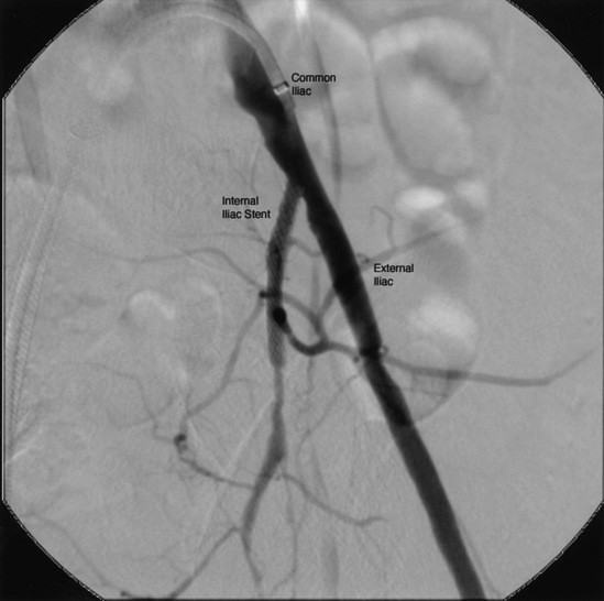
Figure 15-13 Selective left common iliac angiography (20° left anterior oblique [LAO] and 20° caudal view) demonstrating origin of internal iliac artery (IIA) (ostial stent present) and external iliac artery (EIA).
Overlap at the origin of the SFA and DFA arteries commonly occurs in the AP projection and can be improved with a 20° to 30° LAT oblique view.9 Another common source of artifact may occur when the tibial arteries overlie the relatively radiodense bony periosteum of the tibia or fibula. In that case, slight angulation will move the artery in question off the bony density to allow better visualization.
Aortic Arch and Brachiocephalic Vessels
The aortic arch includes portions of the ascending, transverse, and descending aorta (Fig. 15-14). The thoracic aorta gives rise to the brachiocephalic trunk in the proximal portion of the arch, the left common carotid artery in the mid-portion, and the left subclavian artery in the distal portion. In 10% to 20% of cases, the left common carotid artery originates from the brachiocephalic trunk, an anatomical variation known as a bovine arch (Fig. 15-15). Other common variations include the left vertebral artery originating directly from the aortic arch, between the left common carotid artery and left subclavian artery, and the right subclavian artery originating from the aortic arch distal to the origin of the left subclavian artery.
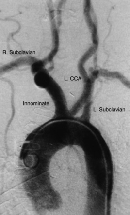
Figure 15-14 Aortic arch and brachiocephalic vessels.
Digital subtraction angiogram injection of 15 mL per second of contrast material for 3 seconds, with image obtained at 30° left anterior oblique (LAO). CCA, common carotid artery.
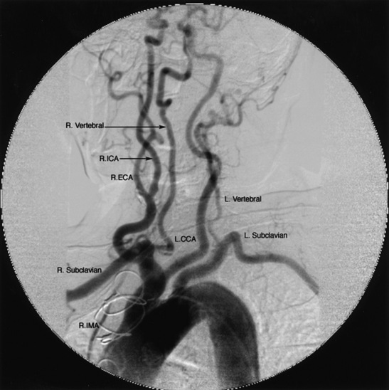
Figure 15-15 Bovine aortic arch angiogram injection of 15 mL of contrast per second for 3 seconds (total 45 mL contrast) at 45° left anterior oblique (LAO).
L.CCA, left common carotid artery; R.ECA, right external carotid artery; R.ICA, right internal carotid artery; R.IMA, right internal mammary artery.
Thoracic aortography is commonly performed to diagnose pathological entities such as stenoses of the origin of the great vessels, aneurysms, aortic dissection, coarctation of the aorta, patent ductus arteriosus, and vascular rings, and to evaluate vascular injuries caused by blunt or penetrating chest trauma.10 Vascular access is most often obtained at the CFA, although the brachial or radial approaches are also useful. A pigtail catheter is advanced into the ascending aorta and positioned proximal to the brachiocephalic trunk. Using a power injector, radiographic contrast material is injected at 15 to 20 mL/sec for a total of 2 to 3 seconds. The LAO projection (30° to 60°) separates the ascending from the descending aorta and allows good visualization of the origin of the great vessels (see Fig. 15-14).
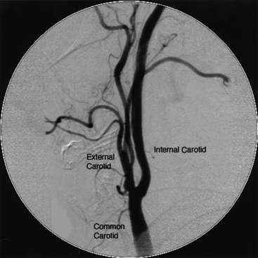
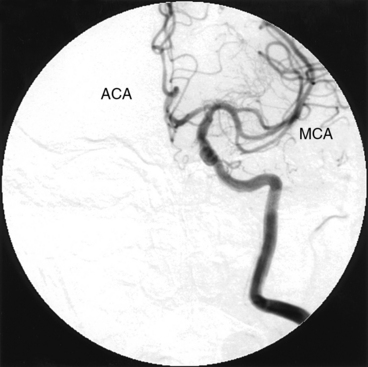
The brachiocephalic trunk, left common carotid artery, and subclavian arteries originate from the transverse thoracic aorta. The brachiocephalic trunk or innominate artery divides into the right common carotid artery and the right subclavian artery. The common carotid arteries run lateral to the vertebral bodies and bifurcate into the external and the internal carotid arteries at about the level of the fourth cervical vertebra (Fig. 15-16). In its extracranial portion, the internal carotid artery has no branches. On entering the skull, the internal carotid artery makes a sharp turn at the carotid siphon and thereafter divides into the middle (MCA) and anterior (ACA) cerebral arteries, from which the anterior communicating artery forms the anterior portion of the circle of Willis (Fig. 15-17).
Carotid Angiography
Selective carotid angiography is usually performed after obtaining an aortic arch aortogram in the LAO view, which allows the operator to visualize the origin of the brachiocephalic trunk and left common carotid artery. Using that same LAO angle, the brachiocephalic trunk is engaged with a diagnostic catheter (Fig. 15-18).
Once the origin of the common carotid artery has been engaged with a guidewire, the catheter is advanced into the common carotid artery over the wire. Care must be taken to clear the catheters and manifold of air and debris before injecting into the carotid artery. Carotid angiograms are obtained in the AP, oblique, and LAT views.
Because of the dense bony structure of the skull, it is preferable to use digital subtraction techniques for diagnostic images of the intracranial vascular anatomy. A 12-inch or larger image intensifier is optimal for intracranial angiography. It is important to emphasize using DSA for the intracranial portion of the internal carotid artery and its branches in the AP and LAT views. This enables assessment of the circle of Willis and demonstrates the presence of any collateral circulation.
Subclavian Angiography
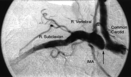
Important branches of the subclavian artery include the vertebral (superior) and internal mammary (inferior) arteries (Fig. 15-19). The vertebral artery, the first and usually largest branch of the subclavian artery, arises from the superior and posterior surface of the subclavian. The AP view will disclose stenosis in the proximal subclavian artery (the left subclavian artery is affected three to four times as frequently as the right subclavian artery). In patients with a tortuous proximal left subclavian artery, a steep right anterior oblique (RAO) view with caudal angulation may help elucidate a proximal stenosis. If the proximal portion of the right subclavian artery is suspected of having a lesion, the AP view may not show the stenosis because of overlap with the origin of the right common carotid artery. A steep RAO caudal view (40°-60° RAO and 15°-20° caudal) will usually separate the ostia of these two vessels (Fig. 15-20).
Vertebral Angiography
The vertebral arteries are identified on the aortic arch aortogram. Often, a nonselective injection of contrast in the subclavian artery near the origin of the vertebral artery is performed to view ostial lesions. Cranial angulation (30°-40°) with shallow oblique views (RAO or LAO), may be necessary to view the origin (see Fig. 15-19). Nonselective angiography is preferred to avoid trauma when engaging the ostium of the vertebral artery with an angled catheter (Judkins right coronary, Berenstein, Cobra, or internal mammary artery catheter). Typically the catheter is placed very near the ostium, and hand injections of contrast are made to visualize the vertebral artery.
The vertebral artery runs cranially through the foramina of the transverse processes of the cervical vertebrae to the base of the skull (Fig. 15-21). After penetrating the foramen of the atlas, it enters the cranial cavity through the foramen magnum. The first branch of the vertebral artery, located in its V4 segment, is the posterior inferior cerebellar artery (PICA). The vertebral artery joins with the contralateral vertebral artery to form the basilar artery (Fig. 15-22).
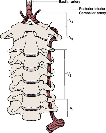
Figure 15-21 Drawing of vertebral artery, divided into four anatomical segments that course through cervical spine foramina.
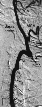
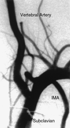
Figure 15-22 Proximal vertebral artery segment visualized with subclavian angiography.
AICA, anterior inferior cerebellar artery; PCA, posterior cerebral artery; PICA, posterior inferior cerebellar artery.
Nonselective angiography is performed with hand injections, using a coronary manifold with pressure monitoring, analogous to selective coronary angiography. Anteroposterior and LAT views of the extracranial and intracranial course of the vertebral and basilar arteries should be performed with a DSA technique. Similar to views of the anterior cerebral circulation, it is important to determine the contribution of the posterior circulation to the circle of Willis.
Complications of Peripheral Vascular Angiography
Complications of peripheral vascular angiography may lead to significant morbidity or even mortality.5 Complications may be thought of in three categories: (1) access site related, (2) systemic, or (3) catheter induced.11 The best strategy to minimize these complications is to anticipate and avoid them.
Access Site–Related Complications
Vascular access site–related complications include hematoma formation, retroperitoneal hemorrhage, pseudoaneurysm formation, AVF creation, and infection. Access site bleeding is the most frequent complication following femoral arterial access.12 It is important to note that femoral closure devices shorten time to ambulation but also add cost without reducing complications.13 Management of access site bleeding depends on the severity and hemodynamic consequences of bleeding. In general, access site bleeding may be controlled by manual or mechanical compression and reversal of anticoagulation. If bleeding continues despite these steps, more aggressive therapies—including percutaneous intervention or surgical therapy—may be considered.14
Signs and symptoms of retroperitoneal bleeding include hypotension, abdominal distention or fullness, and pain. Diagnosis of retroperitoneal bleeding may be confirmed by computed tomography (CT) or abdominal/pelvic ultrasound. If retroperitoneal bleeding is suspected, anticoagulation should be reversed and discontinued. Volume resuscitation with crystalloid solutions and/or blood products should be administered if volume depletion is clinically evident. If bleeding causes hemodynamic embarrassment (hypotension), emergency angiography from the contralateral femoral artery access site should be performed to identify the bleeding site. Once the bleeding site has been identified, tamponade of bleeding with balloon occlusion will stabilize the patient. If prolonged balloon inflation is not effective in stopping blood loss, consideration may be given to placing a covered stent to seal the leak. Open surgical repair may also be an option to consider.14
A pseudoaneurysm occurs when a hematoma communicates with the arterial lumen. Low arterial punctures (SFA or profunda femoris artery entry) are associated with pseudoaneurysm formation. Other risk factors include female sex, age older than 70 years, diabetes mellitus, and obesity.
Patients with pseudoaneurysms often present with pain at the access site several days following the intervention. On physical examination, a pulsatile hematoma may be present with a systolic bruit. Management of a femoral pseudoaneurysm is dependent on its size, severity of symptoms, and need for continued anticoagulation. A small pseudoaneurysm (< 2 cm) may be observed and often will resolve spontaneously. Larger pseudoaneurysms may be treated with ultrasound-guided compression, percutaneous off-label thrombin injection, endovascular coil insertion, or covered stents. Surgical repair of pseudoaneurysms is usually reserved for failure of less invasive approaches.14
An AVF complicates vascular access when the needle punctures the femoral artery and nearby vein, creating a fistulous communication when the sheath is removed. The risk of creating an AVF is increased by either a high or low femoral puncture, multiple puncture attempts, or prolonged clotting times. Fistulae may not be clinically evident for several days following the procedure. An AVF is characterized by a continuous to-and-fro murmur over the access site. In some cases, there may be a swollen and tender extremity due to venous dilation, and in severe circumstances, arterial insufficiency (steal syndrome) may occur. Diagnosis of an AVF can be confirmed by color flow Doppler ultrasound.
Most AVFs following femoral access are small, not hemodynamically significant, and close spontaneously. Symptomatic AVFs require closure to prevent increased shunting and distal swelling and tenderness.15 Surgical repair, traditional therapy for closure of catheterization-related AVFs when necessary, has been replaced by percutaneous methods in most circumstances. Surgical correction is reserved for those patients who fail a less invasive approach.
Vascular access closure devices are designed to facilitate hemostasis, reduce time to ambulation, and decrease length of hospital stay. All devices currently approved by the U.S. Food and Drug Administration (FDA) have shown favorable results. However, these devices are prone to specific complications and have not been demonstrated to reduce access site complications.16
Systemic Complications
Systemic complications relate to allergic and anaphylactic reactions, as well as nephrotoxicity caused by iodinated contrast agents. Allergic or anaphylactic reactions occur in fewer than 3% of cases, and fewer than 1% require hospitalization.
Nonoliguric creatinine elevation, which peaks within 2 to 3 days and returns to baseline by 7 days, is the usual clinical scenario of contrast-induced nephrotoxicity. Patients at risk for contrast-induced nephropathy are those with baseline chronic renal insufficiency, diabetes mellitus, multiple myeloma, and those who are receiving other nephrotoxic drugs (e.g., aminoglycosides). All patients in general, but those at risk to develop contrast-induced nephropathy in particular, should be well hydrated before and after the procedure, and the amount of contrast volume should be minimized. One randomized trial reported that in patients with renal insufficiency, Iodopaque (iso-osmolar, nonionic) is less nephrotoxic than Omnipaque (low osmolar, nonionic) contrast, but there are conflicting studies.17 Mucomyst (N-acetylcysteine) has shown mixed results in preventing contrast nephropathy.18,19 The Acetylcysteine for the Prevention of Contrast-Induced Nephropathy (ACT) trial, a pragmatic multicenter randomized trial that evaluated acetylcysteine in patients undergoing coronary and vascular angiography was the largest randomized trial conducted to date. However, it demonstrated that acetylcysteine was ineffective in preventing contrast-induced nephropathy.20
Diuretics do not protect against contrast-induced nephrotoxicity. Hydration with half-normal saline for 12 hours before and after the procedure provides better protection against creatinine rise than the combination of hydration and diuretics. Two prospective trials have demonstrated that mannitol does not reduce contrast nephropathy.
Catheter Related Complications
Catheters may disrupt atherosclerotic plaque and cause atheroemboli (also see Chapter 47). When catheters are manipulated in the aorta or brachiocephalic vessels during a thoracic aortogram, stroke is a rare but potentially devastating complication.5,21,22 In general, asymptomatic patients have a lower risk, whereas patients who undergo angiography in the setting of transient ischemic events have a slightly higher complication rate. Patients who develop a neurological complication should have an immediate neurological assessment, and angiography of the culprit vessel should be obtained prior to an emergency CT scan. If an embolic stroke has occurred, one option is to perform catheter-directed thrombolysis and/or angioplasty. In the presence of intracerebral hemorrhage, anticoagulants and antiplatelet agents should be reversed.
Atheroembolism is another cause of renal insufficiency following angiography. Unlike contrast-induced nephropathy, renal dysfunction after atheroembolization usually develops slowly (weeks to months) and some of these patients progress to renal failure. Diagnosis is confirmed by tissue examination (biopsy), and treatment is supportive. Systemic manifestations of atheroembolism include livedo reticularis, abdominal or foot pain, and purple toes associated with systemic eosinophilia (blue toe syndrome).
1. Spinosa D., Angle J., Hagspiel K., et al. Feasibility of gadodiamide compared with dilute iodinated contrast material for imaging of the abdominal aorta and renal arteries. J Vasc Interv Radiol. 2000;11:733.
2. Diaz L., Pabon I., Garcia J., et al. Assessment of CO2 arteriography in arterial occlusive disease of the lower extremities. J Vasc Interv Radiol. 2000;11:163.
3. Huber P.R., Leimbach M.E., Lewis W.L., et al. CO2 angiography. Catheter Cardiovasc Interv. 2002;55:398–403.
4. Ledneva E., Karie S., Launay-Vacher V., et al. Renal safety of gadolinium-based contrast media in patients with chronic renal insufficiency. Radiology. 2009;250:618–628.
5. Armstrong P., Han D., Baxter J., et al. Complication rates of percutaneous brachial artery access in peripheral vascular angiography. Ann Vasc Surg. 2003;17:107.
6. Fitts J., Ver Lee P., Hofmaster P., for the Northern New England Cardiovascular Study G. fluoroscopy-guided femoral artery puncture reduces the risk of PCI-related vascular complications. J Interv Cardiol. 2008;21:273–278.
7. Abu-Fadel M.S., Sparling J.M., Zacharias S.J., et al. Fluoroscopy vs. traditional guided femoral arterial access and the use of closure devices: a randomized controlled trial. Catheter Cardiovasc Interv. 2009;74:533–539.
8. Dotter C.T., Judkins M.P. Transluminal treatment of arteriosclerotic obstruction: description of a new technic and a preliminary report of its application. Circulation. 1964;30:654.
9. Beales J., Adcock F., Frawley J., et al. The radiological assessment of disease of the profunda femoris artery. Br J Radiol. 1971;44:854.
10. Schainfield R., Jaff M. Angiography of the aorta and peripheral arteries. In: Baim D., Grossman W. Grossman’s cardiac catheterization, angiography and intervention. Philadelphia: Lippincott Williams & Wilkins; 2000:293.
11. Singh H., Cardella J., Cole P., et al. Quality improvement guidelines for diagnostic arteriography. J Vasc Interv Radiol. 2002;13:1.
12. Jolly S.S., Amlani S., Hamon M., et al. Radial versus femoral access for coronary angiography or intervention and the impact on major bleeding and ischemic events: a systematic review and meta-analysis of randomized trials. Am Heart J. 2009;157(1):132–140.
13. Arora N., Matheny M.E., Sepke C., et al. A propensity analysis of the risk of vascular complications after cardiac catheterization procedures with the use of vascular closure devices. Am Heart J. 2007;153(4):606–611.
14. Samal A.K., White C.J. Percutaneous management of access site complications. Catheter Cardiovasc Interv. 2002;57:12.
15. Waigand J., Uhlich F., Gross C., et al. Percutaneous treatment of pseudoaneurysms and atriovenous fistulas after invasive vascular procedures. Catheter Cardiovasc Interv. 1999;47:157.
16. Toursarkissian B., Mejia A., Smilanich R., et al. Changing patterns of access site complications with the use of percutaneous closure devices. Vasc Surg. 2001;35:203.
17. Aspelin P., Aubry P., Fransson S., et al. Nephrotoxic effects in high-risk patients undergoing angiography. N Engl J Med. 2003;348:491.
18. Chow W., Chan T., Lo S., et al. Acetylcysteine for prevention of acute deterioration of renal function following elective coronary angiography and intervention: a randomized controlled trial. JAMA. 2003;289:553.
19. Ferrario F., Barone M.T., Landoni G., et al. Acetylcysteine and non-ionic isoosmolar contrast-induced nephropathy: a randomized controlled study. Nephrol Dial Transplant. 2009;24:3103–3107.
20. Berwanger O., for the ACT Investigators. Acetylcysteine for the prevention of contrast-induced nephropathy (ACT) trial: a pragmatic multicenter randomized trial to evaluate the efficacy of acetylcysteine for the prevention of renal outcomes in patients undergoing coronary and vascular angiography. Circulation. 2010;122:2219.
21. Willinsky R., Taylor S., Terbrugge K., et al. Neurologic complications of cerebral angiography: prospective analysis of 2,899 procedures and review of the literature. Radiology. 2003;227:522.
22. Fayed A., White C., Ramee S., et al. Carotid and cerebral angiography performed by cardiologists: cerebrovascular complications. Catheter Cardiovasc Interv. 2002;55:277.