CHAPTER 4 Biomechanics of Removable Partial Dentures
As was stated in Chapter 1, the goal is to provide useful, functional removable partial denture prostheses by striving to understand how to maximize every opportunity for providing and maintaining a stable prosthesis. Because removable partial dentures are not rigidly attached to teeth, the control of potential movement under functional load is critical to providing the best chance for stability and patient accommodation. The consequence of prosthesis movement under load is an application of stress to the teeth and tissue that are contacting the prosthesis. It is important that the stress not exceed the level of physiologic tolerance, which is a range of mechanical stimulus that a system can resist without disruption or traumatic consequences. In the terminology of engineering mechanics, the prosthesis induces stress in the tissue equal to the force applied across the area of contact with the teeth and/or tissue. This same stress acts to produce strain in the supporting tissue, which results in load displacement in the teeth and tissue. The understanding of how these mechanical phenomena act within a biological environment that is unique to each patient can be discussed in terms of biomechanics. In the design of removable partial dentures, with a focus on the goal of providing and maintaining stable prostheses, consideration of basic biomechanical principles associated with the unique features of each mouth is essential. Oral hygiene and appropriate prosthesis maintenance procedures are required for continued benefit of optimum biomechanical principles.
Biomechanics and Design Solutions
Removable partial dentures by design are intended to be placed into and removed from the mouth. Because of this, they cannot be rigidly connected to the teeth or tissue. This makes them subject to movement in response to functional loads, such as those created by mastication. It is important for clinicians who provide removable partial denture service to understand the possible movements in response to function and to be able to logically design the component parts of the removable partial denture to help control these movements. Just how this is accomplished in a logical manner may not be clear to a clinician who is new to this exercise. One method of helping to organize design thought is to consider it as an exercise in creating a design solution.
Designing a removable partial denture can be considered similar to the classic, multifaceted design problem in conventional engineering, which is characterized by being open ended and ill structured. Open ended means that problems typically have more than one solution, and ill structured means that solutions are not the result of standard mathematical formulas used in some structured manner. The design process, which is a series of steps that lead toward a solution of the problem, includes identifying a need, defining the problem, setting design objectives, searching for background information and data, developing a design rationale, devising and evaluating alternative solutions, and providing the solution (i.e., decision making and communication of solutions) (Box 4-1).
The rationale for design should logically develop from analysis of the unique oral condition of each mouth under consideration. However, it is possible that alternative design “solutions” could be applied, and it is the evaluation of perceived merits of these various designs that seems most confusing to clinicians.
The following biomechanical considerations provide a background related to principles of the potential movement associated with removable partial dentures, and the subsequent chapters covering the various component parts describe how these components are applied in designs to control the resultant movements of prostheses.
Biomechanical Considerations
As Maxfield states, “Common observation clearly indicates that the ability of living things to tolerate force is largely dependent upon the magnitude or intensity of the force.” The supporting structures for removable partial dentures (abutment teeth and residual ridges) are living things that are subjected to forces. Whether the supporting structures are capable of resisting the applied forces depends on (1) what typical forces require resistance, (2) what duration and intensity these forces have, (3) what capacity the teeth and/or mucosae have to resist these forces, (4) how material use and application influence this teeth-tissue resistance, and (5) whether resistance changes over time.
Consideration of the forces inherent in the oral cavity is critical. This includes the direction, duration, frequency, and magnitude of the force. In the final analysis, it is bone that provides the support for a removable prosthesis (i.e., the alveolar bone by way of the periodontal ligament and the residual ridge bone through its soft tissue covering). If potentially destructive forces can be minimized, then the physiologic tolerances of the supporting structures are not exceeded and pathologic change does not occur. The forces that occur with removable prosthesis function can be widely distributed and directed, and their effect minimized by appropriate design of the removable partial denture. An appropriate design includes the selection and location of components in conjunction with a harmonious occlusion.
Unquestionably the design of removable partial dentures necessitates mechanical and biological considerations. Most dentists are capable of applying simple mechanical principles to the design of a removable partial denture. For example, the lid of a paint can is more easily removed with a screwdriver than with a half dollar. The longer the handle, the less effort (force) it takes. This is a simple application of the mechanics of leverage. By the same token, a lever system represented by a distal extension removable partial denture could magnify the applied force of occlusion to the terminal abutments, which would be undesirable.
Tylman states, “Great caution and reserve are essential whenever an attempt is made to interpret biological phenomena entirely by mathematical computation.” However, an understanding of simple machines applied to the design of removable partial dentures helps to accomplish the objective of preservation of oral structures. Without such understanding, a removable partial denture can be inadvertently designed as a destructive machine.
Machines may be classified into two general categories: simple and complex. Complex machines are combinations of many simple machines. The six simple machines are lever, wedge, screw, wheel and axle, pulley, and inclined plane (Figure 4-1). Of the simple machines, the lever, the wedge, and the inclined plane should be avoided in the design of removable partial dentures.
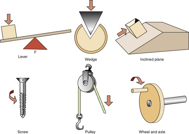
Figure 4-1 The six simple machines include lever, wedge, inclined plane, screw, pulley, and wheel and axle. The fulcrum, wedge, and inclined plane are matters of concern in removable partial denture designs because of the potential for harm if they are not appropriately controlled. F, Fulcrum.
In its simplest form, a lever is a rigid bar supported somewhere along its length. It may rest on the support or may be supported from above. The support point of the lever is called the fulcrum, and the lever can move around the fulcrum (Figure 4-2; see Figure 6-6).
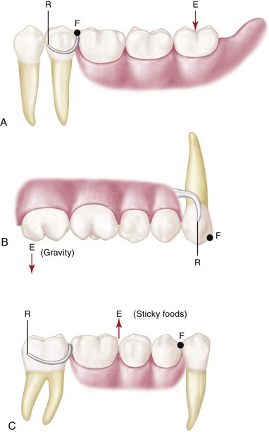
Figure 4-2 A-C, The three classes of levers. Classification is based on location of the fulcrum (F), resistance (R), and direction of effort (force) (E). In dental terms, E can represent the force of occlusion or gravity; F can be a tooth surface such as an occlusal rest; and R is the resistance provided by a direct retainer or a guide plane surface.
The rotational movement of an extension base type of removable partial denture, when a force is placed on the denture base, is illustrated in Figure 4-3. It will rotate in relation to the three cranial planes because of differences in the support characteristics of the abutment teeth and the soft tissue covering the residual ridge. Even though the actual movement of the denture may be small, a lever force may be imposed on abutment teeth. This is especially detrimental when prosthesis maintenance is neglected. Three types of levers are used: first, second, and third class (see Figure 4-2). The potential of a lever system to magnify a force is illustrated in Figure 4-4.
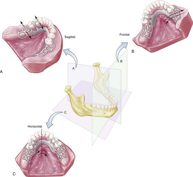
Figure 4-3 Distal extension removable partial dentures will rotate when force is directed on the denture base. Differences in displaceability of the periodontal ligament of the supporting abutment teeth and soft tissue covering the residual ridge permit this rotation. It would seem that rotation of the prosthesis occurs in a combination of directions rather than in a unidirectional way. The three possible movements of distal extension partial dentures are (A) rotation around a fulcrum line passing through the most posterior abutments when the denture base moves vertically toward or away from the supporting residual ridges; (B) rotation around a longitudinal axis formed by the crest of the residual ridge; and (C) rotation around a vertical axis located near the center of the arch.
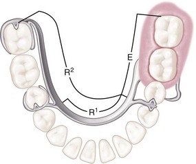
Figure 4-4 The length of a lever from fulcrum (F) (see Figure 4-7) to resistance (R) is called the resistance arm. That portion of a lever from the fulcrum to the point of application of force (E) is called the effort arm. Whenever the effort arm is longer than the resistance arm, mechanical advantage favors the effort arm, proportionately to the difference in length of the two arms. In other words, when the effort arm is twice the length of the resistance arm, a 25-lb weight on the effort arm will balance a 50-lb weight at the end of the resistance arm. The opposite is also true and helps illustrate cross-arch stabilization. When the resistance arm is lengthened (cross-arch clasp assembly placed on a second molar (R2) versus a second premolar [R1]), the effort arm is more efficiently counteracted.
A cantilever is a beam supported at one end that can act as a first-class lever (Figure 4-5). A cantilever design should be avoided (Figure 4-6). Examples of other lever designs and suggestions for alternative designs to avoid or minimize their destructive potential are illustrated in Figures 4-7 and 4-8. The most efficient means of addressing the potential effects of a lever is to provide a rigid element at the unsupported end to disallow movement. This is the most beneficial use of dental implants in conjunction with removable partial dentures (RPDs) and should be considered when support capacity for a distal extension is considered significantly poor.
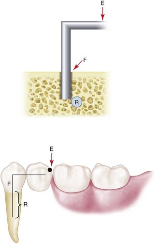
Figure 4-5 A cantilever can be described as a rigid beam supported only at one end. When force is directed against the unsupported end of the beam (as in this rest placed on a cantilevered pontic), the cantilever can act as a first-class lever. The mechanical advantage in this illustration favors the effort arm.
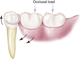
Figure 4-6 Design often seen for a distal extension removable partial denture. A cast circumferential direct retainer engages the mesiobuccal undercut and is supported by the disto-occlusal rest. If it is rigidly attached to the abutment tooth, this could be considered a cantilever design, and detrimental first-class lever force may be imparted to the abutment if tissue support under the extension base allows excessive vertical movement toward the residual ridge.
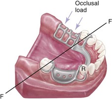
Figure 4-7 As is shown in Figure 4-6, the potential for first-class lever action can also exist in Class II, modification 1 designs for removable partial denture frameworks. If a cast circumferential direct retainer with a mesiobuccal undercut on the right first premolar were used, force placed on the denture base could impart upward and posteriorly moving force on the premolar, resulting in loss of contact between premolar and canine. Tissue support from the extension base area is most important to minimize the lever action of the clasp. The retainer design could help accommodate more of an anteriorly directed force during rotation of the denture base in an attempt to maintain tooth contact. Other alternatives to the first premolar design of the direct retainer would include a tapered wrought-wire retentive arm that uses mesiobuccal undercut, or that just has a buccal stabilizing arm above the height of contour.
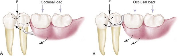
Figure 4-8 Mesial rest concept for distal extension removable partial dentures. With recognition that clasp movement occurs with functional displacement of the distal extension base, the primary aim of a mesial rest is to alter the fulcrum position and resultant clasp movement, disallowing harmful engagement of the abutment tooth. A, Bar type of retainer, minor connector contacting the guiding plane on the distal surface of the premolar, and mesio-occlusal rest used to reduce cantilever or first-class lever force when and if the denture rotates toward the residual ridge. B, Tapered wrought-wire retentive arm, minor connector contacting guiding plane on the distal surface of the premolar, and the mesio-occlusal rest. This design is applicable when the distobuccal undercut cannot be found or created, or when the tissue undercut contraindicates placement of a bar-type retentive arm. This design would be kinder to the periodontal ligament than would a cast, half-round retentive arm. Again, tissue support of the extension base is a key factor in reducing the lever action of the clasp arm. Note: Depending on the amount of contact of the minor connector proximal plate with the guiding plane, the fulcrum point will change.
A tooth is apparently better able to tolerate vertically directed forces than nonvertical, torquing, or horizontal forces. This characteristic is observed clinically, and it seems rational that more periodontal fibers are activated to resist the application of vertical forces to teeth than are activated to resist the application of nonvertical forces (Figure 4-9).
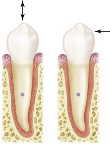
Figure 4-9 More periodontal fibers are activated to resist forces directed vertically on the tooth than are activated to resist horizontally (off-vertical) directed force. The horizontal axis of rotation is located somewhere in the root of the tooth.
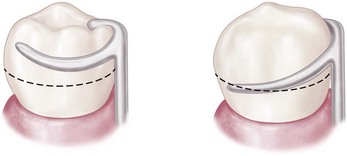
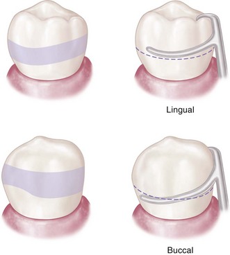
Again, a distal extension removable partial denture rotates when forces are applied to the artificial teeth attached to the extension base. Because it can be assumed that this rotation must create predominantly nonvertical forces, the location of stabilizing and retentive components in relation to the horizontal axis of rotation of the abutment becomes extremely important. An abutment tooth will better tolerate nonvertical forces if these forces are applied as near as possible to the horizontal axis of rotation of the abutment (Figure 4-10). The axial surface contours of abutment teeth must be altered to locate components of clasp assemblies more favorably in relation to the abutment’s horizontal axis (Figure 4-11).
Possible Movements of Partial Dentures
If it is presumed that direct retainers are functioning to minimize vertical displacement, rotational movement will occur about some axis as the distal extension base or bases move toward, away, or horizontally across the underlying tissue. Unfortunately, these possible movements do not occur singularly or independently but tend to be dynamic, and all occur at the same time. The greatest movement possible is found in the tooth-tissue–supported prosthesis because of reliance on the distal extension supporting tissue to share the functional loads with the teeth. Movement of a distal extension base toward the ridge tissue will be proportionate to the quality of that tissue, the accuracy and extent of the denture base, and the applied total functional load. A review of prosthesis rotational movement that is possible around various axes in the mouth provides some understanding of how component parts of removable partial dentures should be prescribed to control prosthesis movement.
One movement is rotation about an axis through the most posterior abutments. This axis may pass through occlusal rests or any other rigid portion of a direct retainer assembly located occlusally or incisally to the height of contour of the primary abutments (see Figures 4-6 and 4-7). This axis, known as the fulcrum line, is the center of rotation as the distal extension base moves toward the supporting tissue when an occlusal load is applied. The axis of rotation may shift toward more anteriorly placed components, occlusal or incisal to the height of contour of the abutment, as the base moves away from the supporting tissue when vertical dislodging forces act on the partial denture. These dislodging forces result from the vertical pull of food between opposing tooth surfaces, the effects of moving border tissue, and the forces of gravity against a maxillary partial denture. If it is presumed that the direct retainers are functional and that the supportive anterior components remain seated, rotation—rather than total displacement—should occur. Vertical tissue-ward movement of the denture base is resisted by the tissue of the residual ridge in proportion to the supporting quality of that tissue, the accuracy of the fit of the denture base, and the total amount of occlusal load applied. Movement of the base in the opposite direction is resisted by the action of the retentive clasp arms on terminal abutments and the action of stabilizing minor connectors in conjunction with seated, vertical support elements of the framework anterior to the terminal abutments acting as indirect retainers. Indirect retainers should be placed as far as possible from the distal extension base, affording the best possible leverage against lifting of the distal extension base.
A second movement is rotation about a longitudinal axis as the distal extension base moves in a rotary direction about the residual ridge (see Figure 4-3). This movement is resisted primarily by the rigidity of the major and minor connectors and their ability to resist torque. If the connectors are not rigid, or if a stress-breaker exists between the distal extension base and the major connector, this rotation about a longitudinal axis applies undue stress to the sides of the supporting ridge or causes horizontal shifting of the denture base.
A third movement is rotation about an imaginary vertical axis located near the center of the dental arch (see Figure 4-4). This movement occurs under function because diagonal and horizontal occlusal forces are brought to bear on the partial denture. It is resisted by stabilizing components, such as reciprocal clasp arms and minor connectors that are in contact with vertical tooth surfaces. Such stabilizing components are essential to any partial denture design, regardless of the manner of support and the type of direct retention employed. Stabilizing components on one side of the arch act to stabilize the partial denture against horizontal forces applied from the opposite side. It is obvious that rigid connectors must be used to make this effect possible.
Horizontal forces always will exist to some degree because of lateral stresses that occur during mastication, bruxism, clenching, and other patient habits. These forces are accentuated by failure to consider the orientation of the occlusal plane, the influence of malpositioned teeth in the arch, and the effects of abnormal jaw relationships. Fabricating an occlusion that is in harmony with the opposing dentition and that is free of lateral interference during eccentric jaw movements may minimize the magnitude of lateral stress. The amount of horizontal movement occurring in the partial denture therefore depends on the magnitude of the lateral forces that are applied and on the effectiveness of the stabilizing components.
In a tooth-supported partial denture, movement of the base toward the edentulous ridge is prevented primarily by the rests on the abutment teeth and to some degree by any rigid portion of the framework located occlusal to the height of contour. Movement away from the edentulous ridge is prevented by the action of direct retainers on the abutments that are situated at each end of each edentulous space and by the rigid, minor connector stabilizing components. Therefore the first of the three possible movements can be controlled in the tooth-supported denture. The second possible movement, which occurs along a longitudinal axis, is prevented by the rigid components of the direct retainers on the abutment teeth and by the ability of the major connector to resist torque. This movement is much less in the tooth-supported denture because of the presence of posterior abutments. The third possible movement occurs in all partial dentures. Therefore stabilizing components against horizontal movement must be incorporated into any partial denture design.
For prostheses capable of movement in three planes, occlusal rests should provide occlusal support only to resist tissue-ward movement. All other movements of the partial denture should be resisted by components other than occlusal rests. Entrance of the occlusal rest into a stabilizing function would result in direct transfer of torque to the abutment tooth. Because movements around three different axes are possible in a distal extension partial denture, an occlusal rest for such a partial denture should not have steep vertical walls or locking dovetails. This rest design is characterized by lack of free movement, which could cause horizontal and torquing forces to be applied intracoronally to the abutment tooth.
In the tooth-supported denture, the only movements of any significance are horizontal, and these may be resisted by the stabilizing effects of components placed on the axial surfaces of the abutments. Therefore in the tooth-supported denture, the use of intracoronal rests is permissible. In these instances, the rests provide not only occlusal support but also notable horizontal stabilization.
In contrast, all Class I and Class II partial dentures, which have one or more distal extension bases, are not totally tooth supported. Neither are they completely retained by bounding abutments. Any extensive Class III or Class IV partial denture that does not have adequate abutment support falls into the same category. These latter dentures may derive some support from the edentulous ridge and therefore may have composite support from both teeth and ridge tissue.
Impact of Implants on Movements of Partial Dentures
Similar to the process of considering how an individual tooth is best used in RPD design to control prosthesis movement, use of an implant should be directed toward the most beneficial movement control. Although possible roles for implant use include all three desired principles demonstrated by prostheses—support, stability, and retention—the major functional demand is imposed by chewing, and therefore the greatest benefit of implant use involves resisting instability by improving support.
In this context, because implants are being considered to augment RPD design and not provide support for a fixed prosthesis, other benefits for the patient include reduced cost and less surgical morbidity. Because cost is typically a major consideration when one is choosing among prostheses, and because use of an RPD provides a distinct cost advantage, selection of the most advantageous position of the implant(s) based on design goals is a primary consideration. Minimizing rotation about an axis in a Kennedy Class I or II arch, or any long modification span, is important to consider.