Chapter 7 Physics of radiography
 In order to standardise the units of measurement used in science, the International System of Units (SI) was developed, which is derived from seven standard base units. Some of these units (e.g. length (metre), mass (kilogram), electric current (ampere)) represent the fundamental measurements underpinning the physics of radiography. From the standard base units, other SI units may be derived which are more applicable to radiography. Electromagnetic radiation is a spectrum of energy levels containing a wide range of radiation types. The inverse square law determines the intensity of radiation reaching both the patient and the image receptor.
INTRODUCTION
It is essential that any practitioner operating within the realms of an imaging department and using ionising radiation has a sound knowledge base. In order to comprehend the various factors affecting the production of diagnostic images, there is a requirement to demonstrate an awareness of the fundamental definitions of classical physics and how these terms may be applied to radiography. An understanding of atomic structure, the electromagnetic spectrum, electricity, magnetism and the inverse square law are also essential principles that can be applied to radiography.
DEFINITIONS
Radiography involves the safe use of ionising radiation and the production of quality images. The process by which images are produced involves the conversion of energy from one form to another and the use of various specialised materials, such as the X-ray tube. The law of conservation of energy states that energy cannot be created or destroyed but merely changes from one form to another. Understanding this fundamental law is central to the basic knowledge base of a practitioner. Within the scope of basic physics there are numerous SI units and their definitions, and the practitioner must be aware of these base units.
SI BASE UNITS RELEVANT TO RADIOGRAPHIC PRACTICE
LENGTH
This is used to measure the size of an object or, in radiography, the distance between different aspects of the imaging system. The SI unit of length is the metre (m) and in radiography one of the most important length measurements is the distance between the X-ray tube focal spot and the imaging receptor. With the advent of digital imaging this distance has become known as the source–image distance (SID), but it is also still widely known as the focus–film distance (FFD). In terms of assessing image quality, the practitioner may wish to use a smaller unit of length, the millimetre (mm), for areas such as focal spot size calculations and image unsharpness. It is important to remember to convert all parameters into SI units before undertaking any calculations.
MASS
Matter is the fundamental material of which everything in the universe is made. Matter is composed of particles known as atoms and molecules. The SI unit of mass is the kilogram (kg). Different materials contain varying amounts of these particles and therefore vary in overall density, and this determines the characteristics of the overall exposure settings used by the practitioner. For example, lead is heavier than wood because it has more densely packed atoms.
ELECTRIC CURRENT
This is the movement of electrons flowing per unit time within a conductive material, such as copper. The SI unit of electric current is the ampere (A) and in diagnostic radiography this determines the quantity of electrons produced by the filament and hence the overall number of X-ray photons in the beam. The term milliamp (mA) is used in diagnostic radiography to express the tube current and is one thousandth of an ampere (10−3 A). The amount of electric charge flowing through an X-ray tube during an exposure is the sum of tube current (mA) and duration of the exposure time in seconds (s). This is expressed as mA s and in order to obtain a short exposure time (e.g. 0.03 s for a chest radiograph) the electric current (mA) needs to be suitably higher.
DERIVED SI UNITS RELEVANT TO RADIOGRAPHIC PRACTICE
Derived SI units result from a combination of the base units and some of them are used frequently in radiography. Practitioners are required to name them and define their values (Table 7.1). Some of these derived SI units are outlined below.
Table 7.1 Common SI units used in radiographic practice
| Term and SI unit | Definition | Application to radiography |
|---|---|---|
| Energy (joule; J) | The ability to do work | Production of X-rays |
| Mass (kilogram; kg) | A measure of the number of atoms and molecules in a body | Important when determining the radiation dose to a patient |
| Gray (joules per kilogram; Gy) | The energy imparted to a body by ionising radiation | Unit of absorbed radiation dose measurement |
| Sievert (joules per kilogram, Sv) | The energy imparted to a body by ionising radiation multiplied by the quality factor | Unit of radiation dose equivalent, which takes biological factors into account |
| Power (joules per second) | The rate of doing work | Output of X-ray generator |
| Electric current (ampere; A) | The movement of electrons flowing per unit time | Quantity of electrons flowing per unit time |
| Electric charge (coulomb; C) | 1 ampere flowing per second | Quantity of electrons flowing per second |
| Electrical potential (volt; V) | The force which moves electrons within a conductive material | Potential difference across an X-ray tube, acceleration of electrons and quality of X-ray beam |
| Frequency (hertz; Hz) | The number of cycles per second | Electromagnetic radiation |
ENERGY
This may be a difficult concept to understand but fundamentally energy is the ability to do work. This may be demonstrated in radiography as potentialenergy (PE), which is applied to the negative (cathode) and positive (anode) ends of an X-ray tube, subsequently causing the flow of electrons across the vacuum environment. This is kinetic energy (KE) and is subsequently converted into X-ray energy (photons) when the electrons interact with the anode material (tungsten atoms).
The potential difference between the cathode and anode of an X-ray tube is measured in kilovolts (kV). This determines the acceleration of electrons across the X-ray tube and hence the quality (penetrating power) of the X-ray beam.
POWER
This is the rate of doing work and is measured in joules per second (J s−1) or watts (W). This unit is referred to in terms of the power output of diagnostic imaging equipment generators. For example a typical general X-ray room will have 50 kW generator to supply electric power to the X-ray equipment. However, a mobile X-ray unit may only have a 35 kW generator because the requirement to produce higher exposure values is less.
ATOMIC STRUCTURE
All matter consists of atoms and can be thought of as having a central nucleus surrounded by a cloud of particles called electrons (Fig. 7.1). The diameter of the nucleus is approximately 10−15 m.
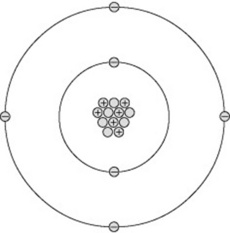
The nucleus contains a number of particles called protons and neutrons, together termed nucleons. Each nucleon is nearly 2000 times the mass of an electron. This means the mass of an atom is concentrated in its nucleus, around which the much lighter electrons orbit. If a nucleus were scaled up to the centre spot of a football pitch, the electrons would start orbiting around the perimeter of the pitch in their various orbits stretching out for several miles. This analogy demonstrates why X-rays may pass through a body of material unattenuated, as the X-ray photons may simply pass ‘between’ the electron orbits and totally miss the nucleus of an atom.
PROTON NUMBER
The proton number (Z), which is the number of protons in the nucleus of an atom (also known as its atomic number), determines the element. For example, a nucleus with just one proton is hydrogen (Z = 1); a nucleus with eight protons is oxygen (Z = 8) and one with 29 protons is copper. The names of all the different elements and their proton numbers can be found in the Periodic Table.
NUCLEON NUMBER
The nucleon (or mass) number (A) of a nucleus is the total number of nucleons in the nucleus; that is, the number of protons plus the number of neutrons. If you subtract the proton number from the nucleon number you will end up with the number of neutrons in the nucleus. Tungsten is used as the anode material in an X-ray tube construction and has a nucleon number of 184 and a proton number of 74. This means tungsten has 74 protons and 110 neutrons in the nucleus of each atom.
ELECTRONS
Electrons are the small, light particles orbiting the nucleus of an atom. They are arranged in shells, called K, L, M, N, O and P. Normally, the number of electrons orbiting the nucleus equals the number of protons in the nucleus. An atom of oxygen, for example, has 8 electrons orbiting the central nucleus in the K shell (n = 2) and L shell (n = 6) (Fig. 7.2).
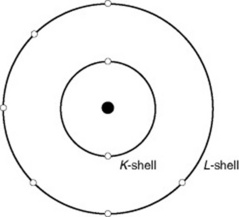
The number of electrons in each shell follows certain rules; for example, the maximum number in the K shell is 2; in the L shell, 8; and in the M shell, 18. However, the outermost shell (valence shell) may only hold 8 electrons. This shell determines the chemical, thermal, optical and electrical properties of the atom. The maximum number of electrons in a shell is 2n2, where n = the number of the shell, starting with K as 1.
Copper, for example, has a proton number of 29. There are 2 electrons in the K shell, 8 in the L shell, 18 in the M shell and 1 in the N shell. This single valence electron easily leaves the atom and acts as a free electron. Hence copper is a good conductor of heat and electricity.
An element is the simplest form in which matter exists. Examples include oxygen, nitrogen and tungsten. Each element only contains atoms of each particular chemical; in other words, the element oxygen only contains the specific atoms for this chemical. Most elements are unable to exist in a single form so they combine with other elements and become compounds. Examples of compounds include water, which comprises two atoms of hydrogen combined with one atom of oxygen. This is chemically expressed as H2O.
ISOTOPES
The number of neutrons in a nucleus can vary, either occurring naturally or artificially. For example, a nucleus of carbon (proton number 6) may have a nucleon number of 11, 12, 13 or 14, with 5, 6, 7 or 8 neutrons. Each is called an isotope of carbon. Carbon-14 is used to date historical artefacts (e.g. the Turin shroud), whilst carbon-12 is used as a reference tool to determine the atomic mass of all other elements. Some isotopes are stable and some are radioactive, depending on the ratio of protons to neutrons.
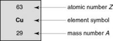
CHEMICAL SYMBOLS
An element can be represented by its chemical symbol (Fig. 7.3) with its proton number as a subscript and its nucleon number as a superscript to the left hand side of the symbol. An element identified in this way is known as a nuclide. Expressing the nuclide in this way gives the practitioner all the information required to illustrate the number of protons and neutrons (nucleons in the nucleus) and the number of orbiting electrons. For example, carbon-14, which has a proton number of 6 but a nucleon number of 14 (i.e. it has 8 neutrons) can be represented as 14C. The proton number could appear as a subscript, but as carbon, by definition, has six protons, that is not strictly needed.
PARTICLE CHARGE AND BINDING ENERGY
The fundamental particles of an atom may have a small charge (1.602 × 10⁻¹⁹ coulomb) associated with them. Protons are positively charged (+1) and electrons are negatively charged (−1). An electrically balanced atom has the same number of protons and orbiting electrons. This charge creates a force (binding energy) which holds the electrons in orbit around the nucleus, and the atom is stable. If an electron is removed from the atom, the positive protons will outnumber the remaining negative electrons, leaving the atom with a net positive charge. This is the process of ionisation of the atom and leaves what is known as a positive ion. When an electron is removed from a shell (e.g. X-ray production), a certain amount of energy is used to overcome the attractive force of the protons in the nucleus: this is called the binding energy. The more protons in the nucleus, the higher the binding energy required to remove an electron. The closer the shell to the nucleus, the higher the binding energy. Atoms may also be ionised by X-ray photons: the energy of the X-ray is used to overcome the binding energy of one of the electrons. If atoms making up important structures in the body, such as DNA, are ionised, chemical changes occur which may cause permanent damage. This is why X-rays can be dangerous and this is why the practitioner needs to be aware of the potential damage from ionising radiation.
ELECTROMAGNETIC RADIATION
The electromagnetic radiation (EMR) spectrum encompasses a wide range of radiation types, such as X-rays, gamma rays, light, microwaves and radio waves. Figure 7.4 depicts the EMR spectrum and, as the term suggests, EMR consists of both electric and magnetic fields. These fields are at right angles to each other and travel through a vacuum at the same velocity as light (3 × 10⁸ m s−1). Outside a vacuum environment,EMR interacts with matter, which may absorb part of this energy and affect it.
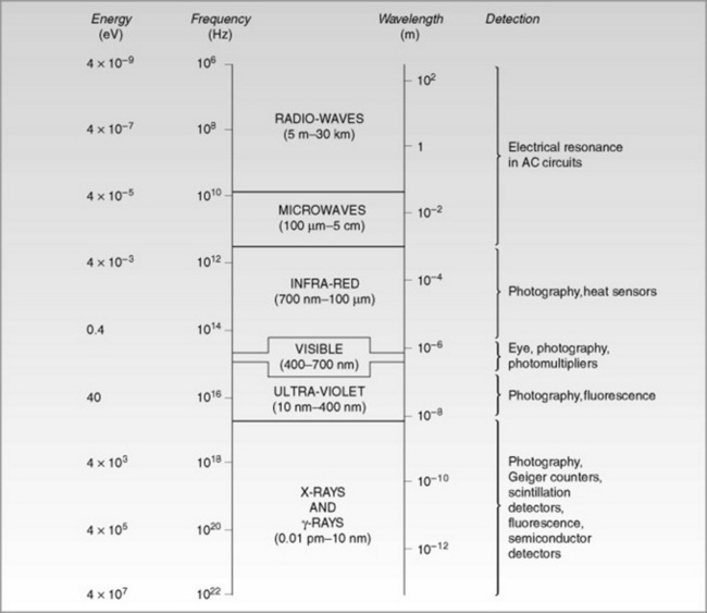
As illustrated in Figure 7.4, the EMR has a range of frequencies and wavelengths. All EMR exhibit the same set of properties. EMR may be illustrated by plotting the energy against distance, giving a sine wave.
In terms of diagnostic imaging, all aspects of the EMR spectrum are relevant to some area of clinical practice (Table 7.2).
Table 7.2 Aspects of electromagnetic radiation (EMR) within the clinical imaging department
| Aspect of EMR | Clinical use |
|---|---|
| X-rays | Obtaining diagnostic images |
| Gamma rays | Nuclear medicine |
| Ultra-violet light | Conventional film–screen combinations |
| Visible light | Viewing radiographs |
| Radio waves | Radiofrequency pulses in MRI |
| Infra-red light | Heat transfer from the anode of a rotating anode X-ray tube |
MAGNETISM
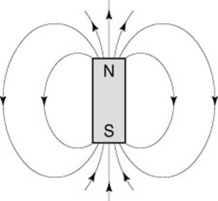
Most practitioners are aware of the concept of a magnet – a piece of metal that aligns itself with magnetic north (compass). This can be used with a map to find your way when out walking. This is a permanent magnet and has a north and a south pole. It is made of iron, which has been magnetised to fulfil this function and is constructed of a series of mini bar magnets all aligned in the same direction. A piece of wire will also exhibit magnetism when an electric current is passed through it. If the wire is coiled it is known as a solenoid and will exhibit the same properties as a bar magnet providing the current is switched on. Bar magnets have no useful function in an imaging department; however, magnetism has several functions of which the practitioner needs to be aware in order to understand how the equipment functions.
Practitioners must also be aware that there are forces which exist between magnets. ‘Like’ poles repel each other and ‘unlike’ poles attract. Thus, if a north pole of a magnet approaches another north pole they will repel each other and you will be unable to get the magnets to touch. However, if one magnet is rotated they will become firmly attached at the poles. It is normal practice in physics to consider the north pole as positive and the south pole as negative. A magnet also exhibits magnetic fields, which exert a force around it, and this can be demonstrated by using iron filings, which adhere to the lines of force (Fig. 7.5).
MAGNETIC FLUX
The number of lines of force that pass through the magnet is defined as the magnetic flux and, if we consider a unit area of the magnet, this then becomes the flux density. The SI unit of magnetic flux density is the tesla (T) and this defines the field strength in magnetic resonance imaging (MRI).
ELECTROMAGNETISM
Magnetism is associated with the alignment and movement of electrons and therefore the atom. As all atoms have moving electrons around their nucleus there are always weak magnetic forces associated with atoms. Therefore, when a current passes through a wire there are millions of electrons moving along the wire and it is this process which cause the wire to become magnetised. The wire also exhibits a magnetic field around it and this effect is known as electromagnetism. Single strands of wire exhibit a magnetic effect; however, to enable us to use the phenomenon effectively we need to coil the wire to make a solenoid. If a soft iron bar is place within the solenoid this increases the magnetic flux considerably because of the induced magnetism within the iron. The combination of a solenoid with an iron core is known as an electromagnet.Electromagnets are used in equipment as locks for the X-ray tube mounting.
MAGNETIC MATERIALS
Some materials are easily magnetised and produce strong magnets whilst other are ineffective at producing magnets. There are three basic types of magnetic substance:
Both diamagnetism and paramagnetism are extremely weak processes and have no application in radiography.
Ferromagnetic substances can be used practically in X-ray equipment and are used in transformers, relays and MRI equipment. These materials have magnetic domains within them and all the atoms are lined up in the same direction. This can be achieved by an externally applied magnetic field; for example by stroking a piece of iron with a magnet or from an electric current.
Metals such as iron and nickel are ferromagnetic and the force required to line up all the magnetic domains is less than in other metals. This process is sensitive to temperature changes and will disappear at extreme temperatures.
ELECTROMAGNETIC INDUCTION
This is the production of an electric current by changing the magnetic field and is the opposite effect of electromagnetism, which was described earlier. It is an important concept in radiography and is the process by which transformers convert the mains voltage to the high current required to produce X-ray exposures. Transformers also isolate the X-ray circuit from the mains electricity by using an autotransformer.
ELECTRICITY
Electricity is simply moving electric charges; that is, electrons moving within a wire. Metals are good electrical conductors. The electrons in their outer shell (conduction band) are easily dislodged and these free electrons can then flow around a piece of wire, creating an electrical circuit. Insulators are materials such as plastic and rubber which have firmly bound electrons in their outer shell and are thus unable to pass an electric current.
ELECTRIC CURRENT
An electric current flowing through a material is simply a measure of the number of electrons passing from the cathode to the anode. The measure of that current is the rate of flow of the electrons. For the electrons to flow there must be a force (potential difference) to drive the electrons and a complete circuit to pass around.
The SI unit of electric current is the ampere and for a current of 1 ampere to flow a charge of 1 coulomb must pass a point in the circuit every second (i.e. 1 ampere = 1 coulomb per second).
This is a considerable number of electrons and amounts to 6 × 10¹⁸ electrons per second. The potential difference across the circuit is measured in kilovolts and determines the rate at which the electrons move. High potential differences are used in the X-ray circuit and vary between 40 and 150 kVp (see p. 108).
TUBE CURRENT
For an X-ray tube to produce X-rays a current must pass from the anode to the cathode and this tube current is measured in milliamperes (mA). Thus the mA is the rate of flow of electrons across the X-ray tube. The total number of electrons flowing for each exposure is the product of the mA and the duration of the exposure (mA s).
RESISTANCE
Resistance is the force which tries to impede the flow of electrons. It is measured in ohms (Ω) and the resistance in any material depends upon its shape, the type of substance and the temperature of the material. Metals have low resistance to the passage of electrons whereas insulators have muchhigher values of resistance. The optimum shape of a conductor to reduce the resistance is one of large cross-sectional area and, of course, the longer the conductor the greater the resistance.
INVERSE SQUARE LAW
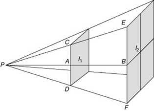
The inverse square law is a fundamental aspect of everyday practice within diagnostic imaging and is a principle which every practitioner should understand. As previously mentioned, EMR is composed of quanta, each of which has energy. As the distance between the X-ray source (e.g. X-ray tube) and imaging receptor increases the intensity of the radiation emitted will decrease.
The intensity (I) of a diverging beam (e.g. an X-ray beam) when passing through air adheres to an inverse square law with distance (d) from the source via the following mathematical formula:

The intensity of the X-ray beam decreases with an increase in distance. This happens due to the diverging nature of the X-ray beam rather than to the interaction of X-ray photons with matter. The energy of the X-ray beam is spread over an increasing area as the distance from the source increases. By doubling the distance, the intensity is reduced to a quarter of its original value. This is demonstrated in the Figure 7.6, where the result of increasing the distance from d1 to d2 results in a reduction of the intensity of the X-ray beam to a quarter of that of d1.
THE INVERSE SQUARE LAW IN PRACTICE
In practice, the inverse square law needs to be taken into consideration when undertaking examinations, which may require a large distance. For example, examinations involving the inclusion of a full-length tibia and fibula view may require the practitioner to increase the SID to accommodate this part of the anatomy. Such an increase in distance is outside the normal working distance of 100 cm SID and will require an adjustment to the exposure factors in order to provide an image with the same density and contrast as an image produced at the standard SID.
Example of inverse square law
Question: The reading from a dose area product (DAP) meter was 1041 mGy cm2 (see Table 7.1 for SI units) for a phantom pelvis examination performed at 100 cm SID. What is the approximate DAP meter reading for the same examination (using the exact same exposure factors) at 200 cm SID?
Answer: Substituting into the equation given above, we can see that 1/d2 increases from 1/1002 to 1/2002 when the distance doubles. So if I ∝1/10 000 and has a value of 1041 mGy cm2, then I ∝1/40 000 must have a value of 1041 × ¼, which means the absorbed DAP is reduced to approximately 260 mGy × cm2. The resultant image would, however, appear with less contrast and not as dense in comparison to the image taken at 100 cm, as only the higher energy portion of the X-ray beam would reach the image receptor. The lower energy X-ray photons would either be absorbed or scatter, potentially failing to reach the image receptor. This is demonstrated in the images in Figure 7.7.

However, with the advent of digital imaging systems, certain image algorithms may be applied to raw data and compensation for the effects of distance may be visualised by the practitioner. The practitioner should be consciously aware of the post manipulation features of modern digital imaging systems.
Ball J, Moore AD. Essential physics for radiographers, 3rd edn. London: Blackwell, 1997.
A clear and straightforward introduction to physics for radiographers..
Farr RF, Allisy-Roberts PJ. Physics for medical imaging. London: Saunders, 1997.
This text provides information on medical physics, assuming you have a good base of physics knowledge..
Graham DT, Cloke P. Principles of radiological physics, 4th edn. London: Churchill Livingstone, 2003.
This book provides an in-depth introduction to the physics of diagnostic radiography. The presentation is clear and easy to understand with examples applying the theory to practice..