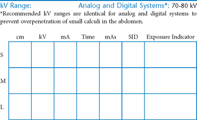
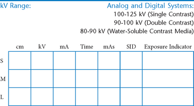
Abdomen and Common Contrast Media Procedures
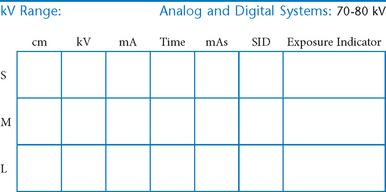
• Shielding and positioning landmarks
• Barium distribution and body positions
 AP supine and AP erect critique
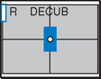
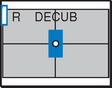
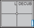
Lateral and dorsal decubitus critique
AP supine and erect abdomen critique
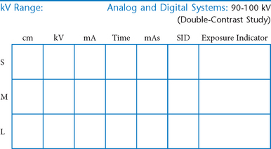
R and L lateral decubitus (double contrast)
AP/PA axial (butterfly position)
Lateral decubitus and AP/PA axial critique
AP and posterior oblique critique
Posterior obliques and lateral
Abdomen and Common Contrast Media Procedures
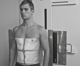
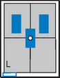
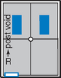
Shielding and Positioning Landmarks
Gonadal Shielding
Male:
Gonadal shields should be used on all males of reproductive age, with upper edge of shield placed at symphysis pubis unless it obscures essential anatomy.
Females:
Ovarian gonadal shields placed correctly may be used for abdomen examinations on females of reproductive age only if such shields do not obscure essential anatomy for that examination as determined by a radiologist (shielding is especially important for children).
Pregnancies
Generally no radiographic procedures exposing the pelvic region should be performed during pregnancy without special instruction from a radiologist/physician.
Topographic Positioning Landmarks
Certain positioning landmarks are essential for positioning the general abdomen and specific organs within the abdomen because the borders of these organs and the upper and lower margins of the general abdomen itself are not visible from the exterior.
Abdominal borders and organ locations, however, can be determined by certain landmarks, which can be located by gentle palpation with the fingertips, being careful of painful or sensitive areas. (The patient should be informed of the purpose for this before beginning the palpation process.)
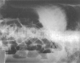
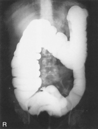
Barium Distribution and Body Positions
The air-barium distribution within the stomach and large intestine changes with various body positions. By knowing these distribution patterns, one can determine in which body position a radiograph was taken. Air always rises to the highest levels, and the heavy barium settles to the lowest levels (air is black, barium is white).
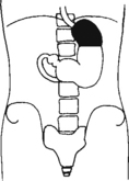
Stomach
The fundus is located more posteriorly; therefore in the supine position it would be the lowest portion of the stomach and would be filled with barium.
In both prone and erect positions, the fundus would be filled with air as seen on the drawings below, with a straight air-barium line on the erect.
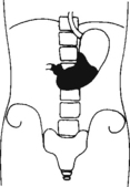
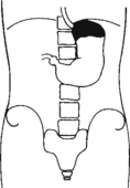
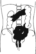
Large Intestine
The ascending and descending portions are located more posteriorly, and thus more of these parts in general would be filled with barium (white) in the supine position and with air (black) in the prone position.
Note:
This much separation of barium and air occurs generally only with double-contrast barium-air studies.
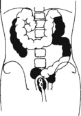
Air-fluid levels would be seen in the erect position in which the air would rise to the highest position in each of the various sections of the large intestine, as shown in the accompanying figure.
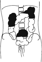
Right and left decubitus projections (not shown on these drawings) also would demonstrate air-fluid levels, with air again rising to the highest portions.
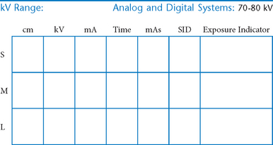
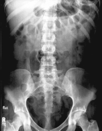
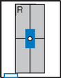
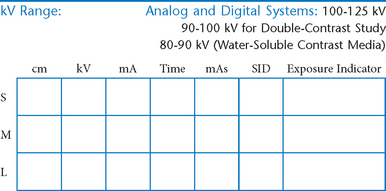
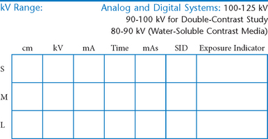
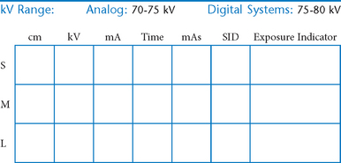
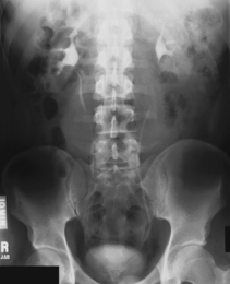
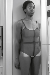
AP Abdomen (KUB)*
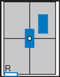
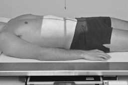
Position
• Supine, legs extended, arms at sides
• Midsagittal plane aligned and centered to centerline
• Ensure no rotation (ASISs equal distance from tabletop)
• Center of IR to level of iliac crests, ensuring that upper margin of symphysis pubis is included on lower IR margin. (A large hypersthenic patient may require that the IR be placed crosswise with a second IR centered higher.)
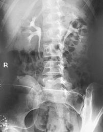
Erect AP Abdomen*
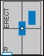
AP Supine and AP Erect Abdomen

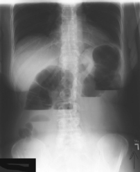
Abdomen*
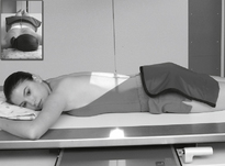
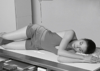
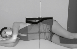
• Arrow marker to include upside
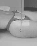
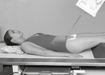
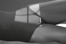
• Patient should be on side a minimum of 5 minutes before exposure; 10 to 20 minutes is preferred.
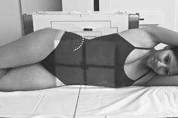
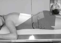
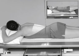
Position
• Patient on side (on decubitus board or support to elevate downside abdomen), knees partially flexed, arms up near head
• Adjust patient and stretcher so center of IR and table (and CR) is approximately 2″ (5 cm) above level of iliac crest (to include diaphragm)
• Adjust height of IR to ensure that upside of abdomen is included for possible free air

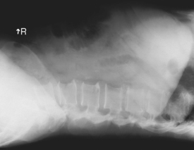
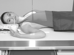
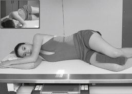
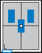
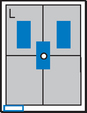
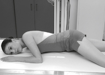
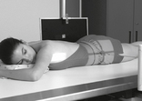
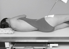
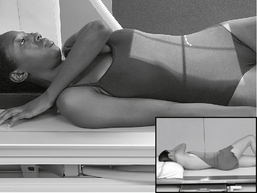
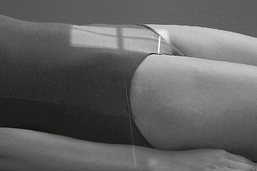
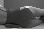
Abdomen*
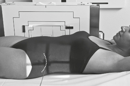
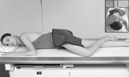
Position
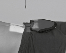
• Patient supine (on decubitus board or support to elevate posterior abdomen), side against table, arms above head
• Secure stretcher (lock wheels)
• Center of IR and table (and CR) at level of iliac crest (2″ above iliac crest to include diaphragm)
• Adjust height of IR to align midcoronal plane to centerline of IR
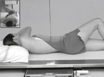
Lateral and Dorsal Decubitus Abdomen
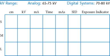
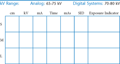
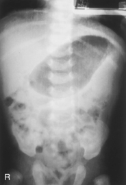
AP Pediatric Abdomen (KUB)*

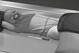
Position (Infant)
• Immobilize arms above head (use stockinette, Ace bandage, tape, or sandbags).
Parental Assistance for Infant:
Use only if necessary. Supply with lead apron and gloves, and have parent hold arms above head with one hand and legs with other hand, preventing rotation.
AP Erect Pediatric Abdomen*

Position
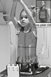
Parental Assistance:
If necessary, have parent hold arms overhead with one hand, and with other hand hold legs to prevent rotation of pelvis or thorax (provide with lead apron and gloves).
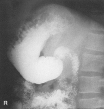
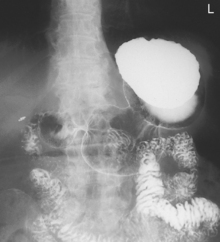
Esophagogram—RAO*

Esophagogram—Lateral*
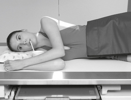
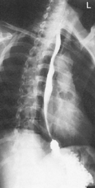
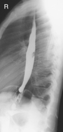
Esophagogram—AP (PA)*

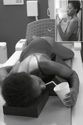
Upper GI—PA*

Upper GI—RAO*

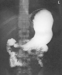
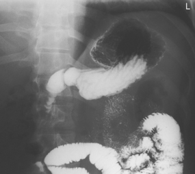
Upper GI—Lateral*

Upper GI—AP*

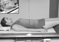
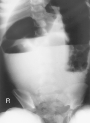
Fig. 9-31 AP supine Trendelenburg, upper GI (stomach) (Trendelenburg position best demonstrates hiatal hernia).

Lateral and AP Upper GI
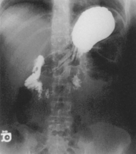
Upper GI—LPO*

Small Bowel Series—PA*
A common routine includes images at 15- or 30-minute intervals until barium reaches ileocecal valve.
Position
• Prone preferred (may be taken AP supine if necessary)
• MSP aligned to centerline; no rotation
• Center patient and IR to iliac crest (center higher on early IRs).

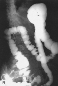
Barium Enema—PA or AP*
Position
• Patient prone (PA) or supine (AP); work quickly
PA (AP) Barium Enema
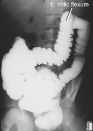
Barium Enema—RAO and LAO*
Oblique Barium Enema
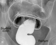
Barium Enema—Lateral Rectum (Ventral Decubitus)*

Alternative ventral decubitus projection is often performed for double-contrast studies.

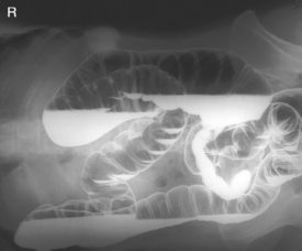
Barium Enema—Lateral Decubitus*
Both right and left lateral decubitus are commonly taken as part of a double-contrast series.

Lateral Decubitus and AP/PA Axial Barium Enema
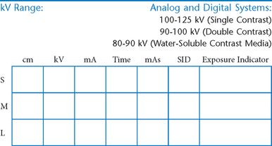
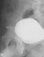
Intravenous Urogram*
• 35 × 43 cm L.W. (14 × 17″); 28 × 35 cm (11 × 14″) C.W. for nephrotomography

Position
• Supine, midsagittal plane aligned and centered to centerline, support placed under knees, no rotation
Intravenous Urogram*

AP and Posterior Oblique IVU
Evaluation Criteria
Intravenous Urogram*
Position
• Erect, midsagittal plane aligned and centered to centerline, no rotation
• Center IR to iliac crest—ensure that bladder area, including the symphysis pubis, is included at lower IR margin.

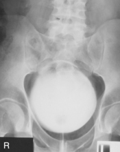
Cystogram—AP*

Cystogram—Posterior Obliques*
(RPO, LPO, and Optional Lateral)

Note: Cystogram routine may not include a lateral because of high gonadal dose.
*Bontrager Textbook, 8th ed, p. 116.
*Bontrager Textbook, 8th ed, p. 119.
*Bontrager Textbook, 8th ed, p. 118.
*Bontrager Textbook, 8th ed, p. 120.
*Bontrager Textbook, 8th ed, p. 644.
*Bontrager Textbook, 8th ed, p. 645.
*Bontrager Textbook, 8th ed, p. 478.
*Bontrager Textbook, 8th ed, p. 479.
*Bontrager Textbook, 8th ed, p. 480.
*Bontrager Textbook, 8th ed, p. 483.
*Bontrager Textbook, 8th ed, p. 482.
*Bontrager Textbook, 8th ed, p. 484.
*Bontrager Textbook, 8th ed, p. 486.
*Bontrager Textbook, 8th ed, p. 485.
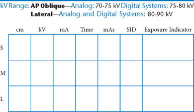
*More rotation for hypersthenic patients
*Bontrager Textbook, 8th ed, p. 513.
*Bontrager Textbook, 8th ed, p. 515.
*Bontrager Textbook, 8th ed, pp. 516 and 517.
*Bontrager Textbook, 8th ed, p. 519.
*Bontrager Textbook, 8th ed, p. 520.
*Bontrager Textbook, 8th ed, p. 523.
*Bontrager Textbook, 8th ed, p. 554.
*Bontrager Textbook, 8th ed, p. 556.
*Bontrager Textbook, 8th ed, p. 557.
*Bontrager Textbook, 8th ed, p. 559.
*Bontrager Textbook, 8th ed, p. 559.