Introduction to Computers
Computer Architectures and Processing Capabilities
In Chapter 1, an overview of computed tomography (CT) was presented and a brief history reviewed, followed by an outline of the growth of CT technology from the time it was invented to its current clinical applications and its uses in nonclinical areas, such as scanning baggage at airports, for example. An important point made in Chapter 1 emphasized that computers play an important role in the production of a CT image, and they are a major component of the CT imaging system. With this in mind, it is mandatory for technologists to have a good understanding of what a computer is and how it works.
The purpose of this chapter is to outline the basic technical elements of computers and to highlight certain relevant characteristics that will serve to enhance the reader’s understanding of CT principles.
COMPUTERS IN RADIOLOGY
Today, computers are used in all facets of human activity. They are successfully being used in government, education, energy, transportation, the military, robotics, the home, and health and medicine, to mention only a few. In 1955, computers were used to calculate radiation dose distributions in cancer patients (Seeram, 1989), which subsequently led to the use of computers in radiology. Radiology computer applications are now commonplace and currently fall into two categories: imaging and nonimaging applications. Therefore, technologists should have a certain degree of computer literacy that Capron (2005) defines as awareness (how they are used), knowledge (what they are and how they work), and interaction (being able to use the computer).
Imaging Applications
Imaging applications are those modalities in which the information acquired from the patient is subject to computer processing. Such processing involves digital image processing techniques to produce computer-generated or digital images. In medical imaging, computers are major components in digital imaging modalities such as CT, computed radiography, flat-panel digital radiography (DR), digital fluoroscopy, digital subtraction angiography, digital mammography, magnetic resonance imaging (MRI), nuclear medicine technologies such as single-photon emission tomography and positron emission tomography (PET), PET/CT, and diagnostic medical sonography. Computers also play an integral role in radiation therapy treatment planning.
The central role of the computer in digital imaging systems is to process and facilitate the display and to archive images and information. Additionally, computers are used as efficient vehicles for communicating images and information to remote areas in an effort to improve patient care by facilitating consultation and shared management of the patient’s medical problem.
Nonimaging Applications
Two major nonimaging applications include a picture archiving and communication system (PACS) and a radiology information system (RIS). The central feature of the RIS is to address elements of patient admissions, scheduling, accounting, billing, film library functions, word processing, statistics, database management, and data communications. The RIS can connect to a hospital information system (HIS), which addresses the needs of all departments in the hospital including laboratory, pharmacy, finance, admissions, and hospital administration. On the other hand, a PACS is an electronic system for archiving, transmitting, viewing, and manipulating images acquired by the digital imaging modalities. PACS has now become commonplace in radiology and is an integral part of a CT imaging system and, of course, the other digital imaging modalities mentioned above. For this reason, it will be described in a little more detail later in the chapter.
COMPUTER SYSTEMS
A computer is a machine for solving problems. Specifically, the modern computer is a high-speed electronic computational machine that accepts information in the form of data and instructions through an input device and processes this information with arithmetic and logic operations from a program stored in its memory. The results of the processing can be displayed, stored, or recorded by use of suitable output devices or transmitted to another location.
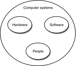
Essentially, people can perform these same tasks; the word computer historically referred to a person. A computer system, on the other hand, consists of at least three elements: hardware, software, and computer users (Fig. 2-1). Hardware refers to the physical components of the machine, and software refers to the instructions that make the hardware work to solve problems. People are essential to computer systems because they design, develop, and operate hardware and software.
These elements result in three core characteristics that reflect the usefulness of computers: speed (solve problems very quickly), reliability (not prone to errors—computers are only as good as the people who program them), and storage capability (storage of a vast amount of data and information) (Capron, 2005).
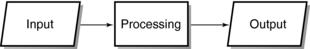
Hardware Organization: A computer processes the data or information it receives from people or other computers and outputs the results in a form suitable to the needs of the user. This is a three-step process (Fig. 2-2).
The organization of a computer includes at least five hardware components: an input device, a central processing unit (CPU), internal memory, an output device, and external memory or storage (Fig. 2-3).
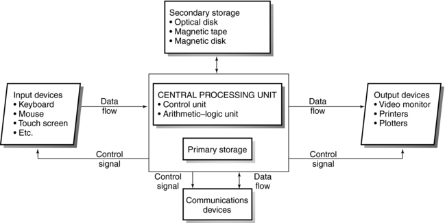
Input hardware refers to input devices such as a keyboard from which information can be sent to the processor. Processing hardware includes the CPU and internal memory. The CPU is the brain of the computer; it consists of a control unit that directs the activities of the machine and an arithmetic-logic unit (ALU) to perform mathematical calculations and data comparisons. In addition, the CPU includes an internal memory, or main memory, for the permanent storage of software instructions and data.
After data are processed, results are sent to an output device in the form of hard or soft copy. One popular hard copy output device is a printer. If the results are displayed on a monitor for direct viewing, then the term soft copy is used. Finally, processing results can be stored on external storage devices. These include magnetic storage devices, such as disks and tapes, and optical storage devices.
Software Concepts: The hardware receives its instructions from the software. The instructions are written in steps that specify ways to solve problems. These sets of instructions are called programs.
The three categories of software are (1) systems software, (2) applications software, and (3) software development tools. Systems software refers to programs that start up the computer and coordinate the activities of all hardware components and applications software. Applications software refers to programs developed by computer systems users to solve specific problems. Software development tools include computer or programming languages such as BASIC, FORTRAN, COBOL, Pascal, DELPHI, C, and C++. Other tools are now available to simplify and expedite the software development process.
Historical Perspectives
The history of the computer dates back 2000 years to the abacus, a counting machine that is based on sliding beads on wires. In 1642, Blaise Pascal developed the arithmetic machine, and in 1694 Leibnitz developed a calculating machine to solve multiplication and division problems. In 1822, Charles Babbage invented the difference engine to calculate mathematical tables. He subsequently used punch card coding to develop the analytical engine, a machine that could solve mathematical problems automatically. During the United States census of 1890, Herman Hollerith introduced the first electronic tabulator based on punch card operation.
The development of computers progressed rapidly with Howard Aiken’s MARK1, a large electromechanical calculator. Eckert and Mauchly’s electronic numerical integrator and calculator and electronic variable automatic computer followed this. In 1951 the universal automatic computer became the first commercially available computer.
Today, computers are in their fifth generation. The term generation indicates a period of significant technical developments in hardware and software. These developments have been characterized by the following events:
• First-generation computers (1951-1958): The principal features were vacuum tubes used for memory. Punch cards and magnetic tape represented input-output media. These machines were large and slow and required an air-conditioned environment because of the amount of heat produced.
• Second-generation computers (1959-1963): These computers were characterized by solid-state devices such as transistors and magnetic cores used for internal memory. These machines were smaller and more reliable and generated less heat than did first-generation computers. In addition, they required less power for operation.
• Third-generation computers (1963-1970): This period was marked by the introduction of the integrated circuit etched onto silicon chips. Magnetic disks were used for storage. These machines were smaller than second-generation computers and performed with greater speed and reliability. Major features included multiprocessing and the rapid evolution of systems and applications software.
• Fourth-generation computers (1971-1987): These computers were based on large-scale integration in which thousands of integrated circuits were set on a chip. The microprocessor was introduced in 1971.
• Fifth-generation computers: The Japanese labeled these computers as “intelligent” and subsequently applications were developed to have computers mimic human intelligence, something referred to as artificial intelligence (AI). AI includes a number of areas such as expert systems (the computer acts as an expert of a certain topic), natural language (“…the study of the person/computer interaction in unconstrained native language”), robotics (“computer-controlled machines with electronic capabilities for vision, speech, and touch”), and problem solving (Capron, 2005).
As noted by Capron (2005), “…the true focus of this ongoing fifth generation is connectivity, the massive industry effort to permit users to connect their computers to other computers. The concept of the information superhighway has captured the imaginations of both computer professionals and everyday computer users.”
Classification
Computers are classified according to their processing capabilities, storage capacity, size, and cost. At present, computers are grouped in four main classes: supercomputers, mainframe computers, minicomputers, and microcomputers.
Supercomputers such as the CRAY-2 and the Blue Horizon supercomputer (IBM) are large, high-capacity computers that can process data at extremely high speeds. They are used in oil exploration studies, weather forecasts, research (especially in weapons), and scientific modeling.
Mainframe computers such as the IBM 3090/600 E are large, high-level computers capable of rigorous computations at high speeds. They have large primary memories and can support many pieces of peripheral equipment such as terminals, which enable multiple users to access the primary memory. Organizations such as banks, universities and colleges, large businesses, and governments use mainframe computers.
Midrange computers were once referred to as minicomputers, an old term that has been defined as “a mid-level computer built to perform complex computations while dealing efficiently with a high level of input and output from users connected via terminals (Microsoft, 2002). Midrange computers are also frequently connected to other midrange computers on a network and distribute processing among other computers such as personal computers (PCs). Midrange computers are used in CT and MRI.
Microcomputers, or PCs, are small digital computers available in a variety of sizes such as laptops or palmtops (notebooks). One category of microcomputers is the workstation, an upper-end PC. Workstations are now commonplace in radiology and are used in several digital imaging modalities including CT and MRI.
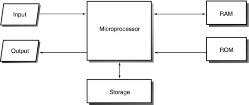
Microcomputers can be built with all circuitry on a single chip or on multiple circuit boards. A central feature is a microprocessor (Fig. 2-4). The microprocessor is a digital integrated circuit that processes data and controls the general workings of the microcomputer (Capron, 2005). Its processing capability is related to the number of bits, which are binary digits (0 and 1) used to represent data. A microprocessor can be either an eight-bit processor that represents 256 (28) numbers or a 16-bit processor that represents 65,536 (216) numbers. The 16-bit microprocessor therefore can process more data faster than an eight-bit microprocessor. Today, 32-bit microprocessors are available for specialized and dedicated applications. This information provides a rationale for why it is important for technologists to have a basic understanding of digital fundamentals, which will be covered later in this chapter.
COMPUTER ARCHITECTURES AND PROCESSING CAPABILITIES
Computer architecture refers to the general structure of a computer and includes both the elements of hardware and software. Specifically, it refers to computer systems, computer chips, circuitry, and systems software.
Types
Essentially, the two types of CPU architectures are complex instruction set computing (CISC) architecture and reduced instruction set computing (RISC) architecture. The CISC microprocessor design has more built-in operations compared with the RISC microprocessor design. Computers with CISC architecture include the IBM 3090 mainframe computer and nearly all microcomputers. Computers with RISC architecture are the IBM 6000, Sun Microsystems SPARC, and Motorola 88000. According to Covington (1991), “RISC is faster if memory is relatively fast so that no time is wasted fetching instructions. CISC is faster if memory is relatively slow because the same work can be done without fetching as many instruction codes.”
These architectures are capable of processing operations such as serial or sequential processing, distributed processing, multiprocessing, multitasking, parallel processing, and pipelining. CT technologists should understand the meaning of these terms because they are used in the CT literature and manufacturers’ brochures.
Terminology
Serial or sequential processing: Information (data and instructions) is processed in the order in which items are entered and stored in the computer. It is a simple form of processing data, one instruction at a time. The following definitions are taken from the most recent edition of the Microsoft Computer Dictionary, published by Microsoft Press.
Distributed processing: The information is processed by several computers connected by a network. True distributed processing “has separate computers that perform different tasks in such a way that their combined work can contribute to a larger goal.…It requires a highly structured environment that allows hardware and software to communicate, share resources, and exchange information freely.”
Multitasking: The computer works on more than one task at a time.
Multiprocessing: Multiprocessing uses two or more connected processing units. “In multiprocessing, each processing unit works on a different set of instructions (or on different parts of the same process). The objective is increased speed or computing power, the same as in parallel processing, and the use of special units called co-processors.”
Parallel Processing: This is a “method of processing that can run only on a type of computer containing two or more processors running simultaneously. Parallel processing differs from multiprocessing in the way a task is distributed over the available processors; in multiprocessing, a process might be divided up into sequential blocks, with one processor managing access to a database, another analyzing the data, and a third handling graphical output to the screen.” A number of processes can be carried out at the same time.
Pipelining: A “method of fetching and decoding instructions in which, at any given time, several program instructions are in various stages of being fetched or decoded. Ideally, pipelining speeds execution time by ensuring that the microprocessor does not have to wait for instructions; when it completes execution of one instruction, the next is ready and waiting.…In parallel processing, pipelining can also refer to a method in which instructions are passed from one processing unit to another, as on an assembly line, and each unit is specialized for performing a particular type of operation.”
DIGITAL FUNDAMENTALS
The two main types of computers are digital and analog. Digital computers operate on digital data (discrete units), and analog computers operate on continuous physical quantities that are not digital but may have any value on a continuously variable scale (analog signals). Analog signals involve physical quantities such as electrical signals (voltage), speed, pressure, temperature, and displacement. An example of an analog computer is the slide rule, which compares the length on the rule and the logarithm of a number.
Digital computers are the most common type of computers; they operate on digital data through arithmetical and logical operations. Because the digital computer is used in all radiology applications, an understanding of the binary number system is important. This will provide a better insight on how computers work.
Binary Number System
An understanding of the decimal number system is necessary to then understand the binary number system. The decimal number system has a base 10, in which 10 values are represented as 0 through 9. Any decimal number can be written as a sum of these digits multiplied by a power of 10. For example, the number 321 can be written as follows:

The number 321 is thus formed from units (1), tens (20), and hundreds (300).
In the decimal system, any number can be expressed as units, tens, hundreds, thousands, tens of thousands, hundreds of thousands, millions, tens of millions, hundreds of millions, and so on. These are referred to as powers of 10 and can be written as follows:
The binary number system, on the other hand, has a base 2, in which only two values, 0 and 1, are represented. A binary number can be 0, 1, a string of 0s, a string of 1s, or a string of 0s and 1s.
The conversion of the decimal numbers to binary numbers and binary numbers to decimal numbers is not within the scope of this chapter. The interested student should refer to any good computer textbook for an understanding of this process.
Other Number Systems
Binary numbers can become very long. For example, the binary number for 1025 is 1000000001. Because this can be time consuming with long numbers, other number systems have been developed, such as the octal and hexadecimal systems. In the octal system, groups of three binary digits are represented by one octal digit. The base of the octal system is 8, in which eight digits are represented by 0, 1, 2, 3, 4, 5, 6, and 7.
The hexadecimal system uses four binary digits (bits) to represent one hexadecimal digit, and the base is 16 in which the 16 digits are represented by 0, 1, 2, 3, 4, 5, 6, 7, 8, 9, 10, 11, 12, 13, 14, and 15. In this case the first 10 digits are represented by 0, 1, 2, 3, 4, 5, 6, 7, 8, and 9; and 10, 11, 12, 13, 14, and 15 are represented by the first six letters of the alphabet, A, B, C, D, E, and F, respectively.
Terminology
A binary digit, or a bit, is a single binary number. In computing, the grouping of bits is as follows:
4 binary bits (0.5 byte) = nibble
16 binary bits (2 bytes) = word
32 binary bits (4 bytes) = double word
Because binary numbers can be long, they are combined into groups of eight bits called bytes. A byte represents one addressable location in memory. Memory capacity is therefore measured in bytes, where
1 thousand bytes = 1 kilobyte (K or KB)
1 million bytes = 1 megabyte (MB)
Binary Coding Schemes
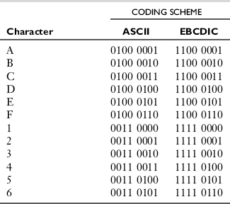
People enter information into a computer for processing in the form of characters (e.g., A, B, C), numbers (e.g., 1, 2, 3), or special characters (e.g., $, *, :,;). These characters must be represented in binary code. Two popular binary coding schemes are extended binary coded decimal interchange code (EBCDIC) and American standard code for information interchange (ASCII) (Table 2-1). Although EBCDIC, developed by IBM, is the industry standard for minicomputers and mainframe computers, ASCII is widely used by microcomputers. When a character is entered into the computer, it is automatically converted into the ASCII or EBCDIC binary code, depending on the computer system.
Elements of a Digital Signal Processor
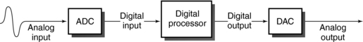
Information is entered into a computer in analog form. If the computer is an analog computer, then the results of processing are also analog. In this case, both the input and output are in analog form. However, if the computer is a digital computer and the input is analog, an analog-to-digital converter (ADC) is needed to convert the analog input into digital data for processing. The results of digital processing are digital data that can be displayed as such but in most instances would have no meaning to an observer. Therefore an interface such as the digital-to-analog converter (DAC) is needed between the digital processor and the output display device. The ADC and DAC, coupled with a digital processor, constitute a digital signal processor (Fig. 2-5).
Analog-to-Digital Conversion: The ADC converts the analog signal into “a sequence of numbers having finite precision” (Proakis, 1992). This procedure is referred to as analog-to-digital conversion. The essential parts of an ADC include a sampler, a quantizer, and a coder (Fig. 2-6). These components perform the following three operations: sampling, quantization, and coding.
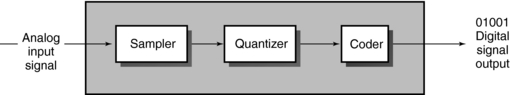
• Sampling is “the conversion of a continuous-time signal into a discrete signal obtained by taking ‘samples’ of the continuous-time signal at discrete time instants” (Proakis, 1992).
• Quantization is “the conversion of a discrete-time, discrete-valued (digital) signal. The value of each signal sample is represented by a value selected from a finite set of possible values” (Proakis, 1992).
• Coding is the assignment of a binary bit sequence to each discrete output from the quantizer.
Digital-to-Analog Conversion: The digital signal processor outputs digital data that are subsequently converted into the analog signals needed to operate analog display devices such as television monitors. This conversion requires a DAC, which is made of solid-state electronics that generate an output voltage proportional to the input digital number.
One important characteristic of the DAC is its resolution, that is, how finely an analog voltage may be represented, which is determined by the number of digital bits. For example, an 8-bit DAC outputs 256 (28) analog voltage as opposed to a 12-bit DAC, which outputs 4096 (212) analog voltages and indicates significantly better resolution.
COMPUTER HARDWARE
In computing, input refers to information entered into the computer for processing. The information can be processed immediately or stored (usually on a magnetic medium such as a magnetic tape or disk) for later processing.
Input hardware can be placed in two categories: keyboard and nonkeyboard devices.
Keyboard Devices: A keyboard is a part of a terminal, which is an input-output device with a display screen. A keyboard is a special electromechanical device that resembles a typewriter keyboard with some additional features. Keyboards are available in different sizes and shapes, but all have at least four common features: (1) regular typewriter keys with alphabet characters, (2) numerical keys (numbers), (3) special function keys called programmable keys, and (4) cursor movement keys (Fig. 2-7). When characters are entered from the keyboard, they are converted into binary codes and are then sent to the CPU for processing.
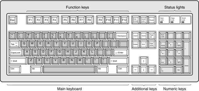
FIGURE 2-7 The main features of a computer keyboard. These include function keys, main keyboard, numerical keys, and additional keys.
There are three types of terminals, as follows:
1. Dumb terminals cannot process information and can only display the input received from the input hardware.
2. Smart terminals can process and store information but cannot perform any programming operations.
3. Intelligent terminals are microcomputers that can process data and store it internally and externally, and therefore they can carry out programming. Communication is also possible through a communications link (a modem).
Nonkeyboard Devices: Nonkeyboard input devices include pointing devices, scanning devices, and voice input devices. Pointing devices are commonly used because pointing appears to be a basic part of human behavior. These devices include light pens, digitizers, touch screens, and the mouse. Scanning devices include image scanners, fax machines, bar code readers (common in supermarkets), and character and mark recognition devices. Voice input devices change human speech into electrical signals, which can then be digitized for processing. These systems are also referred to as voice recognition systems and are an integral part of the digital radiology department (Fig. 2-8).
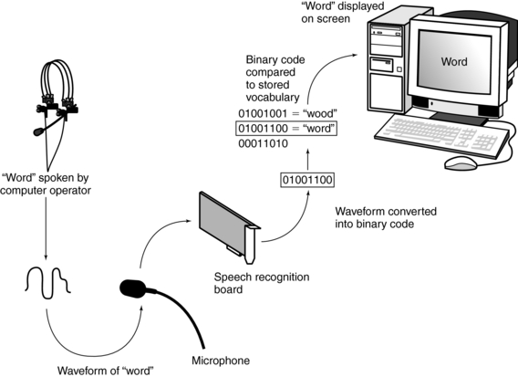
FIGURE 2-8 A voice input device works by translating the sound waves of spoken language into binary numbers that can be interpreted by the computer. If the binary code generated by the speech recognition board finds a match in the computer’s stored vocabulary, that vocabulary word is displayed on the screen.
Input devices play an important role in computer systems, as noted by Stallings et al (1992): “The conversion of data into a computer-usable form is a vital part of a computer-based information system. Input control procedures are needed to safeguard the data’s integrity and to ensure the production of complete and accurate information—inother words, to ensure no ‘garbage in’ to avoid getting ‘garbage out.’”
Processing Hardware
Speed and power are two important characteristics of computers. Speed refers to how fast the computer processes data. Power includes speed and other characteristics such as storage capacity and memory size. Several factors affect the speed of a computer, including microprocessor speed, the bus line size, cache memory, flash memory, RISC architecture, and parallel processing of data.
Microprocessor speeds can range from 1 millisecond (ms = 10−3 seconds) to 1 microsecond (μs = 10−6 seconds) for early computers to 1 nanosecond (10−9 seconds) for modern computers. Research processing speeds continue to approach the picosecond (10−12 seconds) range. These speeds are expressed in cycles per second, megahertz (MHz), or gigahertz (GHz = 109 cycles per second). Additionally, computer speeds can be expressed in million instructions per second (MIPS) or megaflops (MFLOPs).
The processing hardware or CPU includes the control unit, ALU, registers, and memory (see Fig. 2-3).
The control unit directs the activities of the computer through programs stored in memory. For example, it indicates when information is to be moved from memory to the ALU and which operations the ALU should carry out. In addition, the control unit directs the flow of data from the CPU to the input-output hardware.
The ALU executes arithmetic and logic operations including addition, subtraction, multiplication, division, and comparisons such as “is equal to” (=), “is less than” (<), or “is greater than” (>).
Registers are temporary storage electronic devices. They hold the data for a short period and then send it to internal memory, where it is stored temporarily.
The movement of data among these components is accomplished by the bus or bus line, which provides a path for the flow of electrical signals between units. The amount of data transported at a single moment is called the bus width. As noted by Capron (2005), a computer with a larger bus size will be faster because it can transfer more data at one time, will have a larger memory, and can accommodate an increase in the number and variety of instructions.
A computer may have three types of buses: a data bus (data signals), an address bus that sends data from internal memory, and a control bus that sends signals from the control unit.
A major component of processing hardware is primary storage or internal memory, or simply memory. Its purpose is to store (1) the information entered into the computer for processing, (2) the program that provides the instructions for processing the input information, and (3) the results of the processing.
Internal memory is available in the form of chips, semiconductor chips, or integrated circuits. This type of memory is volatile, meaning that data are lost when the computer loses its electrical power. One semiconductor design, the complementary metal oxide semiconductor, requires very little power to operate.
There are two basic types of internal memory chips: read-only memory (ROM) and random- access memory (RAM). ROM chips contain data and programs to make the computer hardware work and cannot be changed, erased, or lost when the computer is turned off; RAM chips provide for temporary storage of data and programs that would be lost if the computer loses power. In addition, RAM can be static (SRAM) or dynamic (DRAM). Although SRAM is faster than DRAM, it does not require refreshing of its contents by the CPU, as does DRAM.
Three additional classes of ROM chips are available: programmable read-only memory (PROM), erasable programmable read-only memory (EPROM), and electrically erasable programmable read-only memory (EEPROM). PROM chips allow users to write their own data and programs but not to change or erase these instructions. With EPROM chips, data can be erased with an ultraviolet light after the EPROM chip is removed from the computer. Finally, EEPROM chips use special software that permit data and programs to be changed electronically without removal.
The storage capacity of RAM chips is expressed in megabytes (MB). Computer programs specify the RAM capacity needed for operation.
Two other types of memory are cache memory and flash memory. Cache memory is very fast memory for the storage of information and data that are used most of the time. It can be internal or external and available on separate chips. Flash memory is nonvolatile. Flash memory chips are being developed for computers and already are used in cellular telephones and flight recorders in airplanes.
Output Hardware
After the input data and instructions have been processed by the CPU, the results can be stored permanently or made available as soft copy or hard copy output. Hard copy refers to printed out-put on permanent media, such as paper and film, and soft copy refers to output “information that has been produced in a seemingly intangible form” (Stallings et al, 1992).
Hard copy output devices include printers, plotters, camera output microforms such as microfiche and microfilm, and voice output devices. Printers fall into two categories: impact and nonimpact. Impact printers make contact with the paper and include letter quality, dot matrix, and high-speed printers. Nonimpact printers include inkjet, thermal, and laser printers. Plotters produce graphics such as three-dimensional drawings, bar charts (graphs), and maps and are categorized as drum, flat bed, and electrostatic. Drum and flat-bed plotters use pens for drawings, and electrostatic plotters use electrostatic charges on a special paper to produce drawings. Voice output devices are based on prerecorded vocalized sounds, and the computer can output synthesized words in response to certain codes.
Soft copy output hardware is based on video display technology. Two common types of video display devices are the cathode ray tube (CRT) and flat-panel or flat-screen devices.
The CRT consists of an electron gun that directs a stream of electrons to strike a phosphor-coated screen located at the opposite end of the gun. Positioned in front of the screen is a shadow mask, which consists of numerous tiny holes that direct a small part of the beam to strike the screen. Each tiny spot that glows on the screen is called a picture element, or pixel. The displayed image on the screen is thus composed of pixels in both the horizontal and the vertical directions. The number of pixels determines the resolution, or sharpness, of the CRT image. In general, the greater the number of pixels (vertical and horizontal), the better the resolution.
Flat-screen output devices are based on flat-screen technologies and were developed primarily for portable computers. Flat-screen display technologies include the liquid crystal display (LCD), electroluminescent (EL) display, and gas plasma display. “LCDs use a clear liquid chemical trapped in tiny pockets between two pieces of glass. Each pocket of liquid is covered both front and back by very thin wires. When a small amount of current is applied to both wires, a chemical reaction turns the chemical a dark color—thereby blocking light. The point of blocked light is the pixel” (Stallings et al, 1992). An EL display panel consists of a phosphor layer that emits light when activated by a current. Two sets of electrodes are arranged with the phosphor layer to form columns and rows. A pixel glows when current flows to the electrodes that address that particular location. The gas plasma display screen is the best of the flat-screen displays. Usually a mixture of argon and neon gases is sandwiched between two glass plates with wire grids. A pixel is displayed when its address location has been charged.
DATA STORAGE TECHNOLOGIES
Approaches to Secondary Storage
There are generally two approaches to secondary storage of information: the sequential access approach and the direct access method. The sequential or serial access method is analogous to finding a favorite song on an audiotape. In this method, information is stored in a specific sequence, such as alphabetically, and the information is therefore retrieved alphabetically. Tape storage is characteristic of this type of storage.
In the direct or random access method, the desired information is accessed directly, so therefore this method is much faster than sequential access. Disk storage is characteristic of this type of storage.
Magnetic Tape Storage: Magnetic tape storage requires a magnetic tape unit with a magnetic tape drive. Magnetic tape is made of Mylar polyester film (DuPont), a plastic-like material coated with particles that magnetize the tape to record information. The tape is threaded from a supply reel to pass by the read-write head and then moves onto a take-up reel.
The read-write head is a wire wrapped around an iron core with one or more small gaps. When information is recorded onto the tape, the electrical signal passing through the wire produces a varying magnetic field that magnetizes the particles on the tape. The direction of the magnetization on the tape represents binary code. When the tape is played back, the magnetization on the tape results in electrical signals that are sent to a display device or audio speakers. Magnetic tape used in conjunction with minicomputers and mainframes is about ½-inch wide and ½-mile long and can store a wide range of characters (O’Leary et al, 1992).
Magnetic tape streamers, also referred to as back-up tape cartridge units, are also available for use with microcomputers. Popular tape cartridges use 0.25-inch wide tape and are available in 1000-foot reels. The data recording method is based on the streaming tape method. According to Stallings et al (1992), “In this method, the data [are] written onto the tape in one continuous stream. There is no starting or stopping, no gaps between blocks (or records) of data being recorded.” The amount of data that can be stored on the tape is its density, or the number of characters per inch (cpi) or bytes per inch (bpi). Today, digital audio tape drives are available to facilitate back-up storage. These tapes are high-capacity tapes and provide very fast access to the data stored on them.
Magnetic Disk Storage: Magnetic disks include floppy disks and hard disks. Floppy disks are made of flexible Mylar plastic, whereas hard disks are metal platters. Both are coated with magnetizable particles that allow data to be recorded and stored as binary code. Each disk consists of concentric tracks and preshaped sectors. A typical disk includes about 17 sectors per track and 512 bytes (4096 bits) of information per sector. Magnetic disks are random access devices, which means that any sector of the disk can be accessed quickly. The tracks on the disk contain dots, each of which represents a bit. The packing density of a track is about 4000 bits per inch.
Floppy disks or diskettes are available in two sizes: the 3½-inch microfloppy disk and the 5¼-inch minifloppy disk (Fig. 2-9). Both disks are made of Mylar plastic encased in plastic jacket covers. Data are stored and retrieved from these disks by means of the head window, where the read-write head of the disk drive makes contact with the disk. Microfloppy disks are commonly used in computing and can store much more data than minifloppy disks. Currently, two-inch microfloppy disks are available in some electronic cameras and personal computers. Iomega created the Zip drive, which can hold nearly 100-megabyte disks, a capacity about 70 times that of the 3½-inch diskettes.

When data files are too large to fit on these diskettes, compression programs are available to remove certain data without loss. Compression is also important when large data files are transmitted to remote locations.
Hard disks are high-capacity storage disks capable of storing more data than floppy disks. They are available as internal hard disks, hard disk cartridges, or hard disk packs. Internal hard disks consist of one or more metal platters positioned in a sealed container that also houses the read-write head. These common disk units are known as Winchester disks. Although internal hard disks have a fixed storage capacity, hard disk cartridges are self-contained and can be easily removed from their drives. In addition, they facilitate the storage of an unlimited amount of data. Hard disk packs have several stacked platters with read-write heads positioned so that as one head reads the underside of the disk above it, the other reads the surface of the disk below it. Hard disks are hermetically sealed to prevent smoke, dust, or other particles from entering the container. These particles may cause a head crash, in which case data are lost.
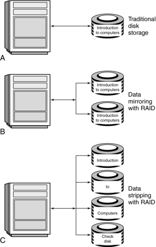
Redundant Array of Independent Disks: Safety is one problem of data and information storage on single disk systems. The redundant array of independent disks (RAID) system overcomes this problem through the use of hard disk technology.
There are several levels of RAID organization (Fig. 2-10). The first level uses disk mirroring in which data are copied onto another set of disks (Fig. 2-10, B). Should one disk fail in this situation, the data are not lost because they are stored on the other disk system. Another level uses data stripping (Fig. 2-10, C ). The data are now distributed across several disks “with one disk used solely as a check disk, to keep track of what data is where. If a disk fails, the check disk can reconstitute the data” (Capron, 2005). RAID is now common in the digital imaging department, where vast amounts of data from several imaging modalities are stored in a safe and secure environment.
Optical Disk Storage: The most recent storage technology is optical storage, which is based on the use of optical rather than magnetic technology. It is a technology in which stored data are read by optical means.
Optical disk storage involves the use of a laser beam (e.g., from a helium-neon laser) to write the data on the surface of a metallic disk. The laser beam is tightly focused to form a spot of light, or the optical stylus, which burns tiny pits onto the concentric tracks (rings) on the disk to write data. The laser beam scans the pits, which reflect light from the disk to a photodetector to read data. The output electrical signal from the detector depends on the geometry and distribution of the pits.
Optical disks are available in diameters of 3½, 4¾, 5¼, 8, 12, and 14 inches. Three types of optical disks are available: compact disc; read-only memory (CD-ROM); write once, read many (WORM); and erasable optical disks. Information can only be read from a CD-ROM by optical means and cannot be recorded or erased. WORM optical disks can write data once to be read multiple times but not erased, which makes this disk suitable for information archives.
Erasable optical disks are made of magneto-optical materials (e.g., gadolinium, terbium, or iron). To write data on the disk, a focused laser beam heats a small region of magnetized ferromagnetic film and causes it to lose its magnetization. The region becomes magnetized in the opposite direction during cooling and in the presence of a magnetic field. In addition, the power of the laser used to write the data is much greater than that used to read the data, which ensures that stored data are not destroyed.
Storage Capacity
The storage capacity of the different storage devices is determined by the number of bytes that the device can hold. Storage capacities are expressed in kilobytes (K), MB, gigabytes (GB), and terabytes (TB). For example, secondary storage capacities for desktop microcomputers are now in the GB range.
COMPUTER SOFTWARE
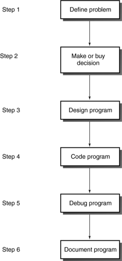
The programmer follows a six-step developmental procedure for programming: (1) define the problem, (2) make or buy the decision, (3) design the program, (4) code the program, (5) debug the program, and (6) document (Fig. 2-11). Step 3 deserves a brief description. Programming techniques such as top-down program design, pseudocode, flow charting, and logic structures are used to arrive at a solution. Although the first two techniques concern major processing steps and a story or narrative of the program logic, respectively, flow charting involves the use of graphical symbols to indicate the sequence of operations needed to solve the problem. The program flow chart includes at least three logic structures: sequence (a program statement), decision, and a loop (the repetition of a process when the condition is true).
The program is coded or written in a programming language available to the computer system. Five generations of programming languages are now available, as follows (see following box):
Machine language, or machine code, is the only language that a computer can understand. It is a low-level language based on sequences of 0s and 1s, which can be represented by on (1) and off (0) switches.
Assembly language is another low-level language that uses abbreviations to develop the program. These must subsequently be converted into machine code with a special program called an assembler.
Procedural languages are considered high-level languages because they are similar to human languages (see following box). According to O’Leary (1992), procedural languages are so named because “they are designed to express the logic—the procedures—that can solve general problems.” Procedural languages include BASIC, COBOL, and FORTRAN, which must be converted into machine code that the computer can process. This conversion is
accomplished by either a compiler or an interpreter. A compiler converts the programmer’s procedural language program, or source code, into a machine language code called the object code. This object code can then be saved and run later.
Problem-oriented languages were developed to simplify the programming process and are intended for use in specific applications. Examples are dBASE and Lotus 1-2-3.
Natural languages are the highest level of programmable languages. These are fifth-generation languages such as Clout and Intellect. The goal of these languages is to resemble human speech. Natural language is now applied to expert systems and artificial intelligence applications.
Applications Software
Applications software refers to programs developed to perform specific types of work such as the creation of text and images, manipulation of words and numbers, or communication of information. Five general-purpose applications programs are common. These are intended for word processing, spreadsheets, graphics, database management, and communications. If all these applications programs are available in one package, the package is referred to as integrated software. Examples include Microsoft Works, First Choice, Framework, and Symphony.
Systems Software
An operating system (OS) is a program that controls “the allocation and usage of computer hardware resources such as memory, central processing unit (CPU) time, disk space, and peripheral devices” (see box below) (Microsoft, 2002). Systems software are programs and data that comprise and relate to the OS. Systems software include at least four types of programs: (1) a bootstrap loader, (2) diagnostic routines, (3) input-output system programs, and (4) the OS.
The bootstrap loader is a program stored in ROM that starts up the computer and loads the OS into primary memory. Diagnostic routines ensure the CPU, primary memory, and other internal hardware are in proper working order. In addition, input-output system programs interpret and input characters and send these characters to output devices. The OS performs system initialization, memory and file management, and input-output control. It also facilitates multitasking and multiprocessing, depending on its capabilities.
Software Interfacing
As defined in the Microsoft Press Computer Dictionary (2002), an interface is the point at which a connection is made between two elements so that they can work together.
Software provides the connection between computer users. Essentially, there are three types of software interfaces: command driven, menu driven, and graphical interfaces. A command-driven interface is characteristic of command-driven programs, which require the user to type in commands from the computer console to initiate the operation of the system. The user must therefore learn and remember a set of commands for various programs. For example, the command DIR, or dir, enables the user of an IBM or IBM-compatible microcomputer to look at the system’s directory.
Menu-driven programs use menu-driven interfaces that allow the user to select commands from a displayed list, menu list, displayed bar, or menu bar. This makes it easier for people to use the system because they do not have to remember numerous commands. In this respect, menu-driven programs are considered user friendly and easier to learn than are command-driven programs.
A graphical user interface enables the user to choose commands, start programs, and see lists of files and other options by pointing to pictorial representations (icons) and lists of menu items on the screen. The concept of a graphical interface was developed at Xerox (Palo Alto Research Center) and originally used by Apple to develop the Macintosh operating system (Arnold, 1991). It is also available for IBM microcomputers as Microsoft Windows or Windows.
Windows can be found on most personal computers. Two important characteristics of Windows are its (1) plug-and-play technology and (2) object-linking and embedding technology. Plug-and-play enables the computer to automatically configure itself when anything new is added; object linking and embedding allows the user to link or embed documents.
Windows NT is noted for its stability and is best suited to networked environments, making it a candidate for use in the digital radiology department. Windows NT is already used in several workstations for medical imaging.
DATA COMMUNICATIONS
Data communications involves the transmission of data from one location to another through the use of pathways. These pathways are referred to as transmission media or channels and include telephone lines, coaxial cables, microwaves, satellites and radio waves, and optical fibers.
The choice of communication channel depends on several factors, of which data transmission speed is relatively important. Data transmission speed is influenced by the baud rate and the bandwidth of the communications channel (Arnold, 1991). The baud rate refers to the number of discrete signal elements (bauds) transmitted per second. The bandwidth refers to the frequency capacity of the channel and is expressed in bits per second (bps) (Arnold, 1991). There are essentially three types of bandwidths: voice band (e.g., a telephone line), which can transmit about 110 to 9600 bps; medium band, which can transmit 9600 to 256,000 bps; and broad band (e.g., coaxial cable, fiberoptics, and microwave), which can transmit 256,000 to 1,000,000 bps.
Data Communications Hardware
A typical data communications scheme sends data from computer A to computer B through the telephone line (Fig. 2-12). The modem modulates, or converts digital data to analog signals, and demodulates, or converts analog signals to digital data; both signals are to be transmitted and received.

Other hardware components include multiplexers, concentrators, controllers, and front-end processors. A multiplexer allows several computers to share a single communications line. A concentrator allows many devices to share a single communications line and is more “intelligent” than a multiplexer because it can store and forward transmissions (Capron, 2005). A controller supports a group of devices such as terminals and printers connected to a computer (Capron, 2005). A front-end processor is a small computer that performs several data management and communications functions, thus relieving the host or main computer of these processing tasks. Telephone companies are now replacing analog phone networks with integrated services digital networks (ISDN), which can handle data communications and also allow audio and video signals to be transmitted simultaneously over cable.
Network Topologies
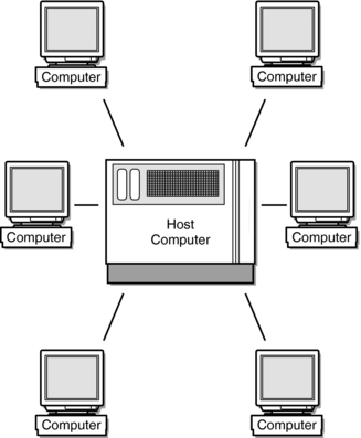
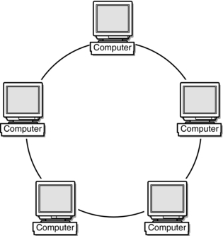
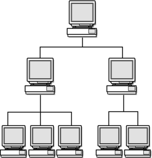
There are four network topologies or configurations: bus, star, ring, and hierarchical. In a bus network (Fig. 2-13), devices such as computers and printers are connected so that each is responsible for its own communications control. The bus cable connects the devices, and there is no host computer or file server. The star network (Fig. 2-14) is characterized by a host computer or file server to which several computers are connected. In a ring network topology, the devices (mostly mainframes) are connected to form a ring without a host computer or file server (Fig. 2-15). The hierarchical network (Fig. 2-16) consists of a central host computer to which other computers are connected. These computers then serve as hosts to several smaller machines. In a typical system, a host computer represents a mainframe that plays host to two minicomputers, which in turn play host to several microcomputers (Capron, 2005; Davidson-Shivers and Rasmussen, 2006).

When computers and other hardware located in the same building are linked through a topology, they create a local area network (LAN) (Fig. 2-17). Figure 2-17 also includes a network gateway that allows the LAN to be connected to other LANs. If the LANs are connected across a region or city, a metropolitan area network (MAN) is created. Similarly, a wide area network (WAN) is created when computers are connected across the country (Davidson-Shivers and Rasmussen, 2006).
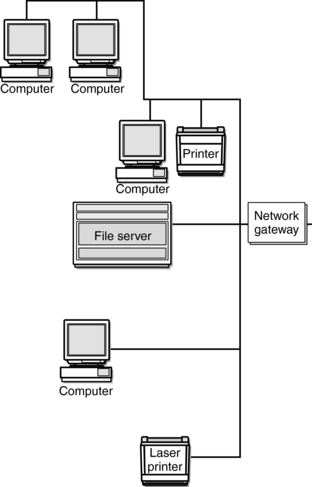
FIGURE 2-17 LAN with a bus topology. The network gateway allows the network to connect to other networks.
LANs, MANs, and WANs require a technology that allows fast communication of the signals. One such technology common to LANs is Ethernet. Ethernet is based on a bus topology in which computers share the same cable to send data. Other technologies include Bitnet and Internet, which are characteristic of WANs.
THE INTERNET
The Internet is the largest computer network system in existence because it connects users all over the world (Davidson-Shivers and Rasmussen, 2006). Concern that a single bomb could destroy the computing facilities of the U.S. Department of Defense led to the creation and development of the Internet in 1959. Efforts were made to rely on one computer system at a single location and a large number of computers at remote locations. Communications between these computers breaks down messages into packets, each of which has a specific destination address and is subsequently reassembled when it arrives at its destination address. Software was then developed to facilitate the communication process. This software is referred to as transmission control protocol/Internet protocol (TCP/IP). TCP manages the packets and their reassembly, and the IP component ensures the packets arrive at their appropriate remote computers.
In 1990, Dr. Berners-Lee developed the worldwide web (www) to facilitate communications with remote computers through a set of links. (The name web refers to his vision of these links as a spider’s web.) Dr. Berners-Lee’s goal was to communicate more easily with his colleagues by linking with their computers.
Major Components
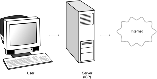
The Internet user must first access a server computer called the Internet service provider (ISP) by a phone line or a direct cable connection. The server computer relays the user’s message to the Internet. Finally, the Internet returns electronic mail (e-mail) or requested information to the user through the ISP server (Fig. 2-18).
A web browser allows the user to use a mouse to point and click on text, drawings, and pictures to facilitate an Internet search. Two popular browsers are Netscape and Internet Explorer. Websites can be located with a uniform resource locator (URL) that must conform to a specific format to ensure successful communications (Davidson-Shivers and Rasmussen, 2006). The URL is the address of the site or file on the Internet. An example of a URL is as follows:
http://www.med.harvard.edu/AANLIB/home.html
The parts of the URL that enable users to access a web page or file include the protocol for communicating links (http://[hypertext transfer protocol]), the ISP address or domain name (www.med.harvard.edu), and the final portion of the domain name, or top-level domain, which demonstrates the type and purpose of the organization. In the above URL, edu indicates an educational institution. The URL ends with path, directory, and file name (AANLIB/home.html). This site features “The Whole Brain Atlas.”
The Internet also features search engines to help users find information in a systematic and organized manner. These are “software programs that assist users in connecting to databases of Web addresses (uniform resource locators, or URLs and that help users locate information on the Web and Internet.…Search engines, therefore, can in turn provide large numbers of pages (called hits) in response to a single search in both text and graphical formats” (Davidson-Shivers and Rasmussen, 2006). Examples of search engines include the popular Google, Alta Vista, Lycos, Yahoo!, Excite, Infoseek, HotBot, Northern Light, and WebCrawler (Davidson-Shivers and Rasmussen, 2006).
To access a search engine, computer users must have the capability of being able to connect to the worldwide web. This connection is facilitated via a browser, popularly referred to as a web browser, such as Netscape Navigator, Microsoft Internet Explorer, and Apple Safari, to mention the more popular ones.
CT AND PICTURE ARCHIVING AND COMMUNICATIONS SYSTEMS
The CT scanner is now connected to the PACS and for this reason a brief overview of PACS is worthwhile here.
Picture Archiving and Communications Systems: A Definition
What is PACS exactly? Some researchers believe that perhaps it should be called IMACS (image management and communication systems); however, the more popular acronym is PACS.
There are several comprehensive definitions of PACS. One such definition, for example, is “…PACS refer to a computer system that is used to capture, store, distribute, and then display medical images. For diagnostic imaging applications, PACS technology can be utilized to achieve near filmless operation” (Siegel, and Reiner, 2002).
A more detailed definition as provided by Arenson et al (2000) is that PACS “…are a collection of technologies used to carry out digital medical imaging. PACS are used to digitally acquire medical images from various modalities such as CT, MRI, Ultrasound (US), Nuclear Medicine (NM), and digital projection radiography. The image data and pertinent information are transmitted to other and possibly remote locations over network, where they can be displayed on computer workstations for soft-copy viewing in multiple locations simultaneously. Data are secured and archived on digital media such as optical disks or tape and can be automatically retrieved as necessary.”
Basically, the two definitions convey the same notion and meaning of PACS except that the second one offers a more detailed picture of PACS.
Picture Archiving and Communications Systems: Major Components
The major components of a PACS and their functional relationships are shown in Figure 2-19. These include digital image acquisition modalities, network switches, PACS controller (as it is often referred to) that includes a database/image server, archive server, short- and long-term archives, RIS/PACS broker, web server, primary and secondary image displays, printer, web-based clinical review, all connected by computer networks. To extend its functionality and usefulness, the PACS is integrated with the RIS and HIS again through computer communication networks. Note that the devices within the PACS communicate with each other, whereas the PACS is integrated with the RIS/HIS. This communication and integration requires the use of communication protocol standards. In this regard, two communication protocol standards are now commonplace in the digital radiology environment.
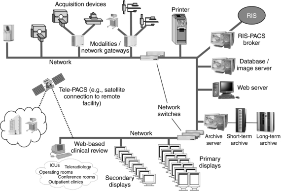
FIGURE 2-19 The major physical components of PACS and their functional relationships. From Samei E et al: PACS equipment overview general guidelines for purchasing and acceptance testing of PACS equipment, Radiographics 24:313-334, 2004. Reproduced by permission.
Communication Protocol Standards: Connectivity refers to a measure of the effectiveness and efficiency of computers and computer-based devices to communicate and share information and messages without human intervention (Capron, 2005; Davidson-Shivers and Rasmussen, 2006; Laudon, 1994).
The use of communication protocol standards is integral to achieving connectivity. Although a protocol deals with the specifics of how a certain task will be done, a standard is an “approved reference model and protocol determined by standard-setting groups for building or developing products and services” (Laudon, 1994).
In health care, HIS, RIS, and PACS, integration is based on different communication protocol standards. Two such popular standards are health level 7 (HL-7) and digital imaging and communications in medicine (DICOM). HL-7 is the standard application protocol for use in most HIS and RIS; DICOM is the imaging communication protocol for PACS (Creighton, 1999). DICOM was developed by the American College of Radiology and the National Electrical Manufacturers Association. Of course in a PACS environment DICOM conformance is mandatory. In a CT-PACS environment, certain DICOM standards are applicable to CT. Some examples of these include storage service class, query and retrieve, print, HIS/RIS, and worklist.
Essential features of an image management and archiving system that is compliant with DICOM and compatible with HIS and RIS include examination acquisition (acquisition of patient demographics) and image acquisition; workflow management; diagnostic, clinical, and enterprise display; and hard copy output. The enterprise display component allows users to view, retrieve, and distribute image data and radiology reports on-line by using the DICOM web server. The nature of possible network systems in radiology is complex.
PACS can be classified according to the size and scope. If a PACS is dedicated to a single digital imaging modality such as CT or MRI scanner, for example, it is usually called a mini-PACS, in which case a single LAN is a central feature.
Networking consists of both hardware components and the necessary software to enable the hardware to function. Networking was described earlier in the chapter. In review, networks can be discussed in terms of LANs or WANs. The basis for this classification is the distance covered by the network. A LAN, for example, connects computers that are separated by short distances such as in a radiology department or in a building or two or more buildings. A WAN, on the other hand, connects computers that are separated by large distances, such as in another province or country. The Internet is a perfect example of a WAN. The network topology for LANs include bus, star, or ring as shown in Figures 2-14, 2-15, and 2-16, respectively.
Image Compression: Once images are acquired and sent through the computer network, they are generally displayed for viewing and stored temporarily or permanently for retrospective viewing and analysis.
The digital images acquired in a total DR department are large files with varying matrix sizes. For example, a typical CT image is usually 512 × 512 matrix by 2 bytes per pixel. These two characteristics alone (matrix size and bit depth) place huge demands not only on storage requirements but also on the speed of transmission over the network.
One effective way to manage the size of image files for transmission and storage is that of image compression. Image compression is a topic in itself that is quite complex and beyond the scope of this chapter; however, it is described in a little more detail in Chapter 3. In this chapter, the following basic facts are noteworthy for CT technologists:
• The purpose of compression is to speed up transmission of information (textual data and images) and to reduce storage requirements
• Several image compression methods are available, each providing advantages and
• disadvantages. Compression can be either:
1. lossless or reversible compression, where no information is lost in the process
2. lossy or irreversible compression, where some information is lost in the process (Seeram and Seeram, 2008)
Picture Archiving and Communications Systems and CT Interfacing
There are several issues related to interfacing a CT scanner to the PACS. These are related to the CT workstation, worklists, image distribution, information systems (RIS/HIS), RIS/HIS/PACS integration, and DICOM specifications. Each of these will be reviewed briefly.
Workstations will be used for primary diagnosis and other viewing tasks, and therefore an immediate concern is to orient radiologists and others such as other physicians and technologists to the nature of the workstation for soft-copy display of images. General hardware and software concerns must be addressed, especially software that allows sophisticated image processing such as three-dimensional imaging and virtual reality imaging.
Worklists are used to match cases from the CT scanner to various workstations, and therefore a PACS must be capable of creating and using worklists effectively (the worklist assignment algorithm is critical).
Image distribution is an important issue for CT PACS and it is the ability of the system to send images to referring physician and the radiation treatment planning department, for example. In this case, DICOM conformance is critical. Additionally, a PACS should be capable of teleradiology applications as well. Images from a CT scanner, for example, can be sent to a radiologist’s home, where he can download them for interpretation. This would certainly save radiologists travel time late at night.
Picture Archiving and Communications Systems and Information Systems Integration
The integration of a CT scanner and PACS is quite critical. Equally important is the PACS integration with the HIS/RIS. Therefore connectivity is important. Several authors such as Bushberg et al (2004) and Dreyer et al (2006), have discussed the role of information systems integration in radiology. They have identified at least five separate information systems for DR, including PACS, RIS, HIS, a voice-recognition direction system, and the electronic teaching/research file system.
Integration of these systems is essential because it is intended to solve many problems in DR. It is not within the scope of this chapter to elaborate on these information systems; however, it is important to delineate between a HIS and a RIS. According to the experts (Van Bemmel and Musen, 1997), HIS is “an information system used to collect, store, process, retrieve, and communicate patient care and administrative information for all hospital-affiliated activities and to satisfy the functional requirements of all authorized users.”
An RIS could be a stand-alone system or it may be integrated into a HIS. Some of the functions performed by the RIS are patient registration, examination scheduling, patient tracking, film archiving, report generation, administration and billing, and documentation, to mention only a few.
OTHER TOPICS
Many other topics in computer science are gaining attention in medical imaging. For example, computer graphics is the basis for three-dimensional rendering techniques such as shaded surface displays and volume rendering, which have become common in three-dimensional CT.
Artificial intelligence: AI is the branch of computer science that deals with enabling computers to emulate such aspects of intelligence as speech recognition, deduction, inference, creative response, the ability to learn from experience, and the ability to make reasonable inferences from incomplete information. AI is a complex arena that includes work in two related areas—one involved with understanding how living things think and the other with finding ways to impart similar capabilities to computer programs. Some tasks that used to be considered very difficult for a computer to perform, such as playing chess, have turned out to be relatively easy to program, and some tasks that were once thought easy to program, such as speech recognition and language translation, have turned out to be extremely difficult. Practical applications in this area include computer-based chess games and diagnostic aids, called expert systems, that are used by physicians and other professionals (Microsoft, 2002).
Computer graphics: Broadly, the term computer graphics refers to the display of “pictures” as opposed to only alphabetical and numerical characters on a computer screen. It encompasses different methods of generating, displaying, and storing information (Microsoft, 2002).
Expert system: An expert system is a type of application program that makes decisions or solves problems in a particular field, such as finance or medicine, by using knowledge and analytical rules defined by experts in the field. Human experts solve problems by using a combination of factual knowledge and reasoning ability. In an expert system, these two essentials are contained in two separate but related components, a knowledge base and an inference engine. The knowledge base provides specific facts and rules about the subject, and the inference engine provides the reasoning ability that enables the expert system to form conclusions (Microsoft, 2002).
Virus (computer): A computer virus is a set of illicit instructions that passes itself onto other programs with which it comes into contact (Capron, 2005).
Virtual reality: a system in which the user is immersed in a computer-created environment so that the user physically interacts with the computer-produced three-dimensional scene (Capron, 2005).
Computer-Aided Detection and Diagnosis: Computer-aided detection and diagnosis (CAD) is now being used in CT, especially in the area of lung nodule detection and in CT colonoscopy (Kalender, 2005; Yoshida and Dachman, 2004). In CAD, the computer (software) is used as a tool to provide additional information to the radiologist and other related individuals to make a diagnosis. In other words, the computer output is regarded as a “second opinion.” The purpose of CAD is to improve diagnostic accuracy and to improve the consistency of image interpretation by using the computer results as a guide (Seeram, 2005).
CAD systems are essentially based on two approaches: those that use location of lesions by using the computer to search for abnormal patterns and those that quantify the image features of normal or abnormal patterns There are three major components of a CAD system: image processing, quantitation of image features, and data processing. The computer uses image processing algorithms such as filtering-based Fourier analysis, artificial neural networks, wavelet transform, and so forth, to enhance and extract lesions. Quantitation involves at least three steps to distinguish between lesions and normal anatomical structures. Finally, data processing uses techniques such as rule-based methods and other approaches such as discriminant analysis, artificial neural networks, and the decision tree method to distinguish between normal and abnormal patterns on the basis of features obtained in quantitation (Seeram, 2005).
REFERENCES
Arenson, RL, et al. Computers in imaging and health care: now and in the future. J Digit Imaging. 2000;13:145–156.
Arnold, DO. Computers and society: impact. New York: Mitchell McGraw-Hill, 1991.
Bushberg, JT, et al. The essential physics of medical imaging, 2, Philadelphia: Lippincott Williams & Wilkins, 2004.
Capron, HL. Computers: tools for an information age. Upper Saddle River, NJ: Prentice Hall, 2005.
Covington, MA. Computer science—outline notes. New York: Barron’s, 1991.
Creighton, C. A literature review on communications between picture archiving and communications systems and radiology information systems and/or hospital information systems. J Dig Imaging. 1999;12:138–143.
Davidson-Shivers, GV, Rasmussen, KL. Web-based learning: design, implementation, and evaluation. Upper Saddle River, NJ: Pearson Education, 2006.
Dreyer KJ, et al, eds. PACS: a guide to the digital revolution, 2, New York: Springer Science + Business Media, 2006.
Kalender, W. Computed tomography. Munchen: Publicis MCD, 2005.
Laudon, KC. Management information systems: organization and technology. Englewood Cliffs, NJ: Macmillan, 1994.
Microsoft. Microsoft Press computer dictionary. Redmond, Calif: Microsoft Press, 2002.
O’Leary, TJ, et al. McGraw-Hill computing essentials, 1992-1993. New York: Mitchell McGraw-Hill, 1992.
Proakis, JG. Digital signal processing: principles, algorithms, and applications. New York: Macmillan, 1992.
Seeram E, ed. Computers in diagnostic radiology—a book of selected readings. Springfield, Ill: Charles C. Thomas, 1989.
Seeram, E. Digital mammography—an overview. Can J Med Radiat Technol. 2005;36:15–23.
Seeram, E, Seeram, D. Image postprocessing in digital radiology: a primer for technologists. Journal of Medical Imaging and Radiation Sciences. 2008;39:23–41.
Van Bemmel, JH, Musen, MA. Handbook of medical informatics. Heidelberg: Springer-Verlag, 1997.
Yoshida, H, Dachman, AH. Computer-aided diagnosis for CT colonoscopy. Semin Ultrasound CT MRI. 2004;25:419–431.