Basic Instrumentation
CT Scanner—Basic Equipment Configuration
CT Computer and Image Processing System
Processing Architectures and Hardware
Scanner Control and Image Reconstruction
Image Display, Storage, Recording, and Communications
Options and Accessories for CT Systems
CT SCANNER—BASIC EQUIPMENT CONFIGURATION
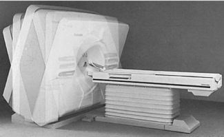
The basic equipment configuration for computed tomography (CT) is illustrated in Figure 7-1. Three major systems are the imaging system, the computer system, and the image display, recording, storage, and communication system. Figure 7-2 shows an earlier unit with the associated major system components.

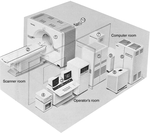
FIGURE 7-2 Components of a CT imaging system. 1, Gantry; 2, patient couch; 3, integrated console; 4, optical disk system including cassette storage; 5, high-speed processor system; 6, x-ray high-voltage generator; 7, couch control unit; 8, system transformer I; 9, system transformer II; 10, patient observation system. Courtesy Toshiba America Medical Systems, Tustin, Calif.
The three major systems are housed in separate rooms, as follows:
1. The imaging system is located in the scanner room.
2. The computer system is located in the computer room.
3. The display, recording, and storage system is located in the operator’s room.
Today, CT scanners are typically housed in similar physical spaces that contain the three system components identified in Figure 7-2.
The purpose of the imaging system is to produce x rays, shape and filter the x-ray beam to pass through only a defined cross-section of the patient, detect and measure the radiation passing through the cross-section, and convert the transmitted photons into digital information. The major components of the imaging system are the x-ray tube and generator, collimators, filter, detectors, and detector electronics. The x-ray tube and generator are responsible for x-ray production. The radiation beam that emanates from the tube is filtered through a specially designed filter that protects the patient from low-energy rays and ensures beam uniformity at the detectors. The collimators help define the slice thickness and restrict the x-ray beam to the cross-section of interest. The detectors capture the x-ray photons and convert them into electrical signals (analog information); the detector electronics, or data acquisition system (DAS), converts this information into digital data.
The computer system receives the digital data from the DAS and processes it to reconstruct an image of the cross-sectional anatomy. In addition, the computer system performs image manipulation and various image processing operations such as windowing, image enhancement, image enlargement and measurements, multiplanar reconstruction, three-dimensional (3D) imaging, and quantitative measurements.
The computer system generally includes input-output devices, central processing units, array processors, interface devices, back-projector processors, storage devices, and communications hardware. The computer system also includes software that allows each hardware component to perform specific tasks. For example, the software enables scanning procedures to be created and activated from an input device and extensive image display and analysis functions such as image pan and zoom, image annotation, multiple image display, windowing, reverse video, image rotation, collage and sagittal-coronal display. Computer hardware and software are described in detail in Chapter 2.
The purpose of the image display, recording, storage, and communication system is as follows:
1. To display the output digital image from the computer in a form meaningful to the observer or diagnostician. CT images are now displayed on flat panel monitors or on cathode ray tube (CRT) monitors. These are highlighted subsequently.
2. To provide a hard copy of the image on a recording medium that provides for a permanent copy of the reconstructed image and accommodates the preference of the radiologist during diagnostic interpretation. Today, film images are no longer available and radiologists now have to make the primary diagnosis from a display monitor in the total digital imaging department.
3. To facilitate the storage and retrieval of digital data to address the problems of film storage and archiving and the environmental concerns of film manufacturing, consumption, and disposal. The filmless imaging department now stores images in the picture archiving and communication system (PACS), briefly described in Chapter 2.
4. To communicate images, diagnostic reports, and patient demographic data in an electronic communications network environment such as PACS and radiology information systems.
IMAGING SYSTEM
The imaging system comprises several components housed in the gantry that work together to acquire an image from the patient. The gantry and patient table or couch are often referred to as the scanner (Fig. 7-3).
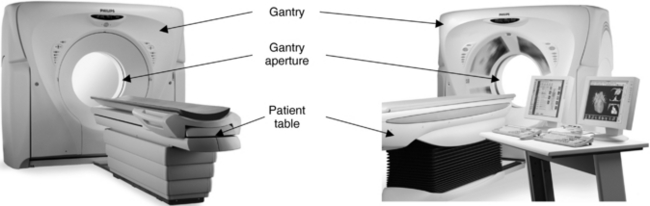
FIGURE 7-3 The external appearance of a CT scanner, showing the gantry, the gantry aperture, and the patient table. Courtesy Philips Medical Systems.
Gantry
The gantry is a mounted framework that surrounds the patient in a vertical plane. It contains a rotating scan frame onto which the x-ray generator, x-ray tube, and other components are mounted.
The gantry houses imaging components (Fig. 7-4) such as the slip rings, x-ray tube, high-voltage generator, collimators, detectors, and the data acquisition system.
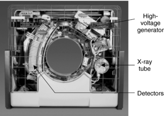
FIGURE 7-4 The gantry houses imaging components such as the x-ray tube and generator, slip rings, collimators, detectors, and detector electronics. Courtesy Philips Medical Systems.
The x-ray tubes of slip-ring scanners require high instantaneous power and therefore have larger anodes with a typical diameter of 5 inches or more. Some CT scanners may incorporate an on-board oil-to-air heat exchanger to assist in cooling the x-ray tube during operation.
The generator in the gantry is usually a small, solid-state, high-frequency generator mounted on the rotating scan frames. Because it is located close to the x-ray tube, only a short high-tension cable is required to couple the x-ray tube and generator. This design eliminates external x-ray control cabinets and long high-tension cables as was typical of the older CT imaging systems.
The power ratings of generators typically range from 30 to 60 kilowatts, depending on the scanner. These ratings enable a large selection of exposure techniques (values such as 80, 100, 120, 130, and 140 kilovolts and about 20 to 500 milliamperes [mA], in 1-mA increments, are not uncommon).
Gantry cooling is a prime consideration because the ambient air temperature affects several components. In the past, air conditioners were placed in the gantry. Modern cooling systems circulate ambient air from the scanner room throughout the gantry.
Two important features of the gantry are the gantry aperture and gantry tilting range. The gantry aperture is the opening in which the patient is positioned during the scanning procedure (Fig. 7-5). The technologist can approach the patient from both the front and back of the gantry. Most scanners have a 70-cm aperture that facilitates patient positioning and helps provide access to patients in emergency situations.
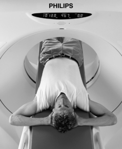
FIGURE 7-5 The gantry aperture is the opening in the gantry in which the patient is positioned for the examination. The diameter of the aperture shown is 700 mm. Courtesy Philips Medical Systems.
The CT gantry must be capable of tilting (Fig. 7-6) to accommodate all patients and clinical examinations. The degree of tilt varies between systems, but ±12 to ±30 degrees in 0.5-degree increments is somewhat standard. The gantry also includes a set of laser beams to aid patient positioning. Other gantry characteristics include scan control panels (controls gantry tilt and patient table elevation, for example), scan control box (controls emergency stop, intercom, and scan enable and pause functions, for example), slice position indicator, radiation indicator, and intercom systems with multilingual autovoice to facilitate communication with the patient in one of several languages.
Patient Table
The patient couch, or patient table, provides a platform on which the patient lies during the examination (see Fig. 7-3). The couch should be strong and rigid to support the weight of the patient. Additionally, it should provide for safety and comfort of the patient during the examination.
The couch consists of a support referred to as the table top, which floats and rests on a pedestal. The couch top is usually made of carbon fiber composites because they have low absorption and provide excellent vibration damping features and meet the strength requirements necessary to take images of heavy patients. The technologist has ample room between the gantry and table for patient access and positioning (Fig. 7-7). The pedestal houses the mechanical and electrical components that facilitate vertical and horizontal couch movements. The vertical movement should provide a range of heights to make it easy for patients to mount and dismount the table (Fig. 7-8). This feature is especially useful in the examination of geriatric, trauma, and pediatric patients. Horizontal or longitudinal couch movements should enable the patient to be scanned from head to thighs without repositioning (Fig. 7-9).
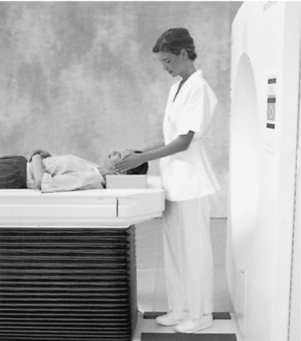
FIGURE 7-7 A design feature of the gantry and table of a CT scanner that facilitates both access to and positioning of the patient. Courtesy Siemens Medical Solutions USA, Inc.
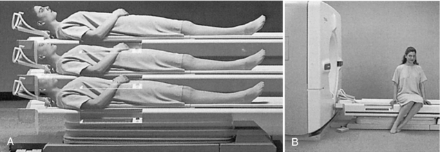
FIGURE 7-8 The vertical movement of the couch can provide a range of heights (A) and allow the patient to mount and dismount the table with little effort (B). Courtesy Toshiba America Medical Systems, Tustin, Calif.
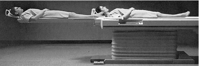
FIGURE 7-9 Longitudinal or horizontal movement of the CT couch (top) should allow the patient to be scanned from head to thigh without repositioning. Courtesy Toshiba America Medical Systems, Tustin, Calif.
Box 7-1 lists the table characteristics for one CT system.
CT COMPUTER AND IMAGE PROCESSING SYSTEM
Processing Architectures and Hardware
The computer system in CT belongs to the class of minicomputers (see Chapter 2). The two most important characteristics of the CT computer system are a large storage capacity and fast and efficient processing of various kinds of data.
Various computer architectures for CT have been developed to accommodate fast image reconstruction and other image processing functions such as image manipulation and visualization software. For example, the evolution of computer architectures for CT scanners first used pipeline processing architectures (Fig. 7-10), followed by the use of parallel and distributed processing architectures (Fig. 7-11) as the processing and clinical application tasks became more sophisticated. The basis for these architectures depends on the way that the computer assigns various tasks (e.g., preprocessing raw data, convolution, back-projection, and visualization tasks such as 3D imaging, CT angiography, and virtual reality imaging) to the numerous processors in its electronic circuits.
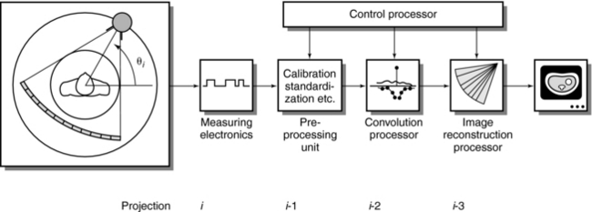
FIGURE 7-10 A historical illustration of a computer configuration of the Siemens Somatom whole-body CT scanner with pipeline processing. The reconstruction steps of preprocessing, convolution, and basic projection are assigned to separate processors. From Dümmling K: 10 years of computed tomography: a retrospective view, Electromedica 52:13-28, 1984.
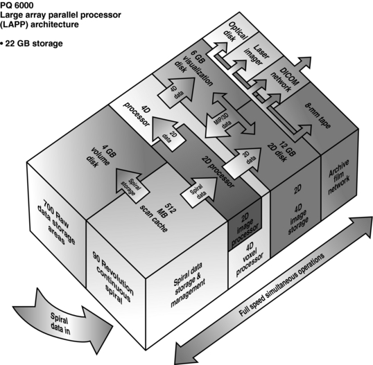
FIGURE 7-11 The Picker PQ 6000 CT Imaging System is based on a large-array parallel processor architecture. Courtesy Picker International, Cleveland, Ohio.
An important component of computer processing architectures for CT and magnetic resonance imaging is the array processor, which is a dedicated electronic circuit capable of the high-speed calculations needed in CT. Array processors feature key elements such as speed, power, flexibility, and expandability. To accommodate these elements, the array processor architecture may consist of the following:
• Multiple dedicated processors (voxel processor) and storage to accommodate high-speed data acquisition such as spiral/helical imaging and two-dimensional (2D), 3D, and four-dimensional image reconstruction, storage, display, and recording
• Dedicated image storage and independent manipulation of data including raw spiral/helical data.
• The Digital Imaging and Communications in Medicine (DICOM) network is the standard for connectivity in radiology. It allows multimodality and multivendor equipment to connect electronically to facilitate data and image communications. DICOM functionality includes, for example, Service Class User and Service Class Provider; DICOM Print; Query/Retrieve; Storage Commitment; and Modality Worklist, to mention only a few.
Scanner Control and Image Reconstruction
The operator must be able to communicate with the system to enable scanning, which may be activated through keyboard commands or a touch screen. In the case of the touch screen, the operator can select prestored protocols, modify protocol parameters, or select the sharp, smooth, or standard algorithm, depending on the CT examination. PC interfaces that use a mouse and drop-down Windows-based menus are increasingly becoming common.
Image Display and Manipulation
A wide range of image display and manipulation techniques is afforded by the CT software. Software is highlighted in a following subsection.
Operating Systems
Operating systems are programs that control the hardware components and the overall operation of the computer; they also enable the computer to run other programs. The operating system consists of a major program called the supervisor, which resides in primary memory and controls all other portions of the operating system. CT computers often use interleaved processing techniques such as multitasking, multiprocessing, and multiprogramming, which allow computers to process several programs almost simultaneously and thus increase the number of jobs the computer can handle at any given time. In addition, the system runs rapidly and efficiently. The operating system used in some CT systems is UNIX compatible and facilitates multiuser and multitasking capabilities. Microsoft Windows NT and XP operating systems have become commonplace in CT scanning.
CT Software
CT software is a special topic in itself that is beyond the scope of this book. It should be noted, however, that the software for CT has been evolving rapidly as more and more clinical applications are made possible by multislice CT scanners that can provide 16 to 64 or more slices per revolution of the tube and detectors.
CT software can be placed in one of three categories, namely, reconstruction software, preprocessing software, and image postprocessing software. Reconstruction software, which builds up the image from the raw data collected from the detectors, consists of very sophisticated algorithms with thousands of lines of coding. Preprocessing software, on the other hand, performs corrections on the data collected from the detectors before the data are sent to the reconstruction computer. Beam-hardening corrections and corrections for bad detector readings are examples of these corrections. Finally, image postprocessing software operates on reconstructed images displayed for viewing to facilitate diagnostic interpretation. For example, a list of what has been popularly referred to as visualization and analysis software is shown in Box 7-2. This software can be placed into two categories: basic and advanced image visualization and analysis tools.
Box 7-3 provides a brief description of several image visualization and analysis software tools. These include tools such as the CT viewer, multiplanar reformation (MPR), maximum or minimum intensity projection (MIP), 3D surface-shaded display reconstruction, Relate Slice, Master Cut, and custom image filters.
Box 7-3 Brief Description of Several Image Visualization and Analysis Software Tools from One Computed Tomography Vendor
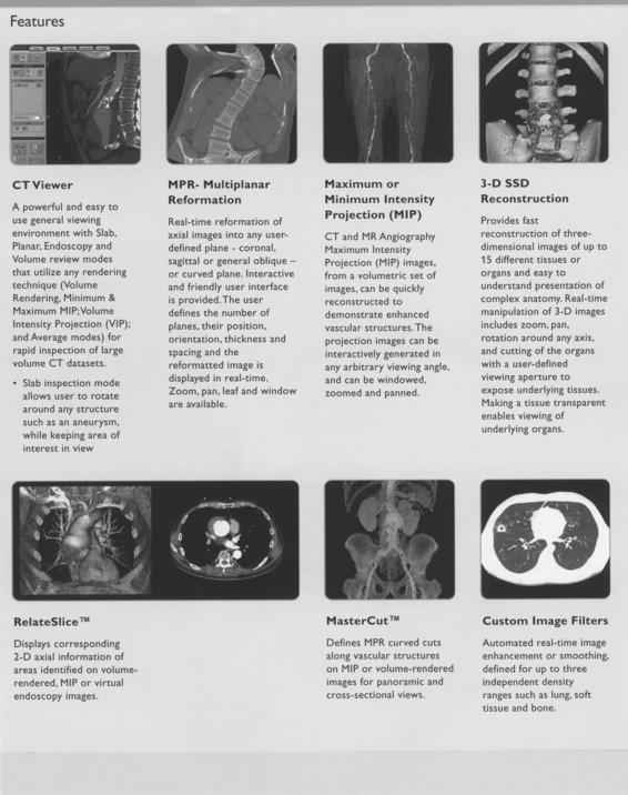
Courtesy Philips Medical Systems.
Finally Box 7-4 briefly describes several other tools, such as 3D small volume analysis, quantitative CT angiography (Q-CTA), combine images, and CT time lapse. Additionally, advanced clinical applications tools such as CT/MR Fusion, functional CT, brain perfusion, and virtual colonoscopy are briefly described.
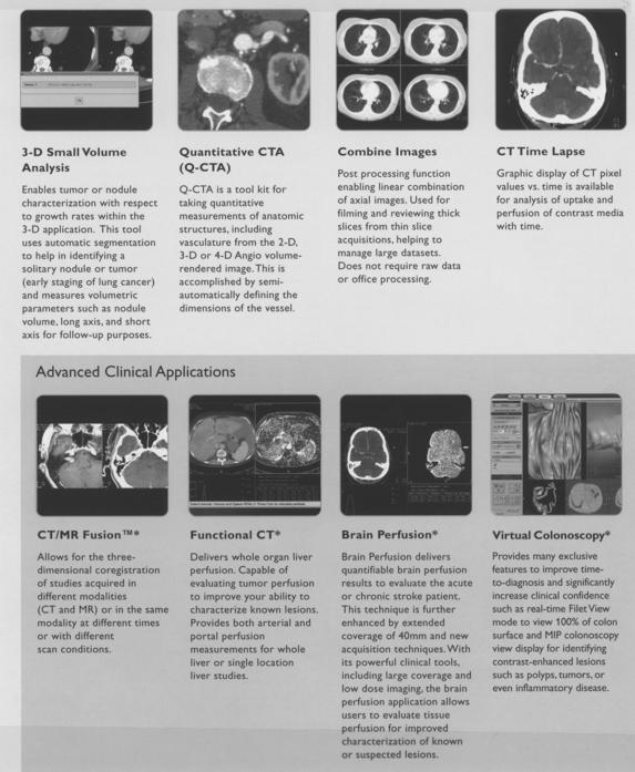
IMAGE DISPLAY, STORAGE, RECORDING, AND COMMUNICATIONS
A display device for CT is generally a black-and-white or color monitor (Fig. 7-12). These can be CRT flat display or liquid crystal display flat-panel display devices. Although images are usually displayed in gray scale, nonimage data such as text fields, patient data, and option selections can be displayed in color.

FIGURE 7-12 A typical CT workstation showing the image monitor and keyboard for image display and data entry, respectively. Courtesy Philips Medical Systems.
The image display system includes such features as the display matrix, pixel size, bit depth, CT value scale, gray scale, image monitor and the number of lines, selectable window width and window center, single and double windows, and highlighting. CT manufacturers provide detailed specifications for each of these features.
Image Storage
Data are stored in digital form to preserve the wide dynamic range of images, including the capability for image processing and intensity transformations, and to decrease the possibility of lost records and reduce the space needed for archiving.
Digital images are stored in 2D pixel arrays; each pixel point is represented by a number of bits that determine how many gray levels can be represented by a particular pixel. CT image size varies according to the anatomy being examined. A typical CT image has a matrix size of 512 × 512 × 8 bytes (12 bits). In this case, each has a gray-level range of 512 (28) to 4096 (212).
A CT image of 512 × 512 × 2 bytes (16 bits) would require 0.5 megabytes (MB) of storage. If the CT examination contains about 50 images, then 25 MB of storage are needed. If 50 examinations are performed in one day, then 1.25 gigabytes (GB) of storage are needed.
Storage devices for CT include magnetic tape and disks, digital videotape, optical disks, and optical tape. It is interesting to note that the capacity of an optical disk simply is so much more than that of magnetic tapes. This is clearly illustrated in Figure 7-13 from the early days of image storage discussions. Today, compact disk (CD) writers can be used for archiving CT images as well.
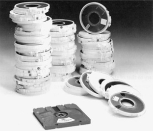
FIGURE 7-13 Optical disk for CT image storage. A single disk can hold the equivalent of 70 magnetic tapes. From Alexander J, Krumme HJ: Somatom Plus: new perspectives in computerized tomography, Electromedica 56:50-56, 1988.
The type of storage devices used, their respective storage capacities, and the typical number of images that can be stored on each device will be different depending on the manufacturer.
Laser Recording System
In the past, the requirements for hard copy recording of CT images were a major consideration during CT imaging because the images were used for diagnostic interpretation. The requirements were broad gray-scale contrast resolution to enable the perception of subtle differences in tissue contrast and high spatial resolution to detect boundaries of different tissues.
Laser image recording systems were used to meet these requirements. Although multiformat video cameras were popular in the past, laser cameras, or laser imagers replaced the video camera technology.
Two types of lasers were used for film recording in CT: solid-state laser diodes and gas lasers such as helium-neon (He-Ne), helium, cadmium, argon, carbon dioxide, and nitrogen. The He-Ne laser is the simplest and most reliable gas laser. The solid-state laser typical of the 3M laser imaging systems has a wavelength of 820 nanometers (nm), but the He-Ne laser has a wavelength of 633 nm. Both systems use infrared-sensitive films (820 nm) and He-Ne laser films sensitive to the 633-nm wavelength beam.
Today laser printing on film is obsolete and is not described further in this book.
Communications
Communications refers to electronic networking or connectivity by using a local-area or wide-area network. Connectivity ensures the transfer of data and images from multivendor and multimodality equipment according to the DICOM standard.
CT scanners must support various network speeds such as 10/100/1000 megabits per second and Ethernet switching for very fast image transfer. CT scanners now feature full implementation of the DICOM communication protocol that allows connectivity to various scanners and workstations in the digital radiology department.
CT CONTROL CONSOLE
CT control consoles have evolved into what is commonly referred to as the integrated console. The multimedia concept allows the operator full control of the physical system (e.g., gantry control) and allows for real-time processing such as multiplanar reformatting, 3D manipulation, zoom, and pan. The integrated console controls the entire system and enables the operation of various functions.
Typically, an integrated console consists of the following components:
• Floating keyboard: Important components include alphanumerical and special function keys, the trackball or mouse, and window controls.
• Touch panel: The touch panel allows system parameters such as scan setup and control parameters to be actuated without typed keyboard commands.
• Window controls: Window controls include the window width and window level controls, which alter picture contrast. Window width refers to the range of CT numbers. Window level is the center of the range.
• Image display: CT images are displayed on monitors for viewing and manipulation by the operator before the final image is communicated to the PACS.
• High-capacity optical disk drive and CD writer: A 9.1-GB erasable optical disk drive is not uncommon.
• Control functions: Various automated functions such as autoarchive, autowindow, and autovoice are featured on CT control consoles. These allow the technologist to devote more time to the scanning procedure and the needs of the patient.
OPTIONS AND ACCESSORIES FOR CT SYSTEMS
A number of options, both hardware and software, are currently available for CT scanners. The hardware options, for example, may include optical disks, optical cartridge tape, remote diagnostic stations, independent workstations, and so forth.
Software options (see Box 7-4) include packages for bone mineral analysis, dynamic scan, 3D image reconstruction, volumetric MPR, evaluation of regional cerebral blood flow (xenon CT), perfusion CT, dental CT, and networking.
Accessories
Accessories support and provide excellent immobilization of the patient to enhance the overall efficiency of the CT examination. These accessories include pediatric cradles, arm and leg supports, elevated and flat head holders, table mattresses, side rails, table extenders, knee supports, head pillows with hand rests, axial and coronal head holders, and radiation therapy table tops, to mention only a few.
OTHER CONSIDERATIONS
The modular design concept is intended to simplify the upgrading of scanners. The hardware modular design concept features detector modules, analog-to-digital conversion cards, tubes, generators and subassemblies, memory boards, array processors, back-projectors, display camera interfaces, and network interface boards. Software modules allow for the easy modification, updating, and revision of software packages to meet the demands of the clinical environment.
Operating Modes of the Scanner
A modern CT scanner can operate in a variety of modes to meet the requirements of various clinical examinations. Typical operating modes include routine scan mode and rapid or dynamic scan mode. Various spiral/helical scan modes such as overlap scan, skip scan, and tilt scan are available to suit the needs of the examination (Fig. 7-14).
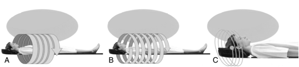
FIGURE 7-14 Three scan modes for spiral/helical CT scanning. Each scan mode includes Overlap Scan, which is useful to make high-quality 3D images. Skip Scan can be used to scan a wide area in a short amount of time. Tilt Scan is used with various gantry tilts. A, High-quality 3D images: overlap scan. B, Short time/wide range scan: skip scan. C, According to head OM line: tilt scan. Courtesy Shimadzu Medical Systems, Seattle, Wash.
Room Layout for CT Equipment
The room layout for CT scanners varies among institutions and depends on the particular type of scanner. A typical room layout (Fig. 7-15) includes at least three sections or rooms to house different components of the scanner, as follows:
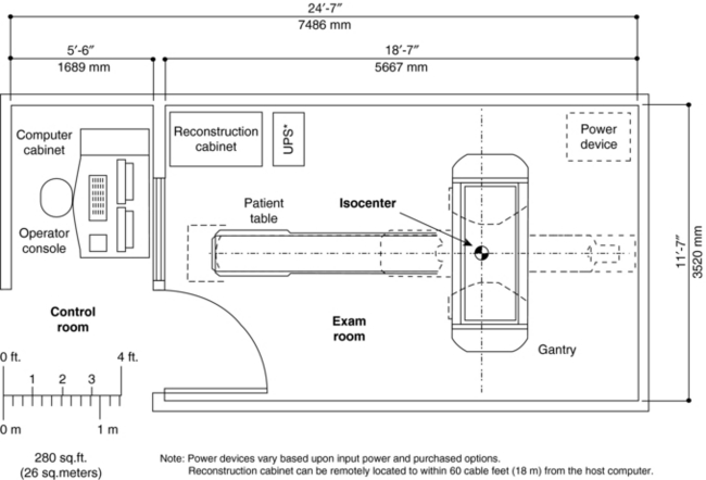
1. The scanning room houses the gantry and patient couch. This room should be large enough to accommodate gurneys and emergency equipment.
2. The computer room generally houses the host computer and other peripheral computing equipment.
3. The control room houses the control console and film recording equipment.
Equipment Specifications
The acquisition of a CT scanner is an interesting experience, and the CT technologist should take advantage of the opportunity to participate in such an activity. The CT department or purchasing committee generally informs the vendor of the necessary equipment specifications. In addition, vendors will have equipment specifications available for review.
In general, several major technical specifications and features of a CT scanner to be considered are as follows:
1. The x-ray generator: both physical and operating parameters
2. The x-ray tube and detectors: heat storage capacity and cooling rates of the tube; the type, quantum detection, and conversion efficiencies of detectors
3. Scanning gantry: aperture size, tilting range, and laser positioning aids and controls
4. Patient couch: movement characteristics and strength of the couch top
5. Operator’s console: characteristics of the display monitor, keyboard, and touch panel control; general ergonomics and storage considerations
6. Physician’s console: hardware and software
7. Computer hardware: the main central processing unit, operating system, and storage device type and capacity
8. Computer software: image reconstruction, display, visualization, and analysis packages
9. Workstations: both hardware and software
11. Quality control equipment; includes phantoms for quality control and radiation dose measurements
BIBLIOGRAPHY
Alexander, J, Krumme, HJ. Somatom Plus: new perspectives in computerized tomography,. Electromedica. 1988;56:50–56.
Fugita, K, et al. Advanced computer architecture for CT,. Radiology. 1992;S:63.
Philips Medical Systems: Brilliance™ CT-64 channel configuration, The Netherlands, 2007, Global Information Center.
Siemens Medical Solutions. CT SOMATOM Sensation, SOMATOM Emotion, and SOMATOM Spirit—product data. Malvern, Pa: Siemens Medical Solutions USA, 2007.
Toshiba America Medical Systems. Aquilion 64 CT scanner. Tustin, Calif: Toshiba America Medical Systems, 2007.