CHAPTER 36 Restorative Therapy
Restorative therapy requires diagnosis and treatment planning by a licensed dentist. In some states and provinces a range of restorative dental treatment may be legally delegated by the dentist to the licensed dental hygienist. Restorative expanded functions (REF) dental hygienists are trained and certified to provide restorative therapies. Their numbers are increasing as a response to access to care. Wide variability exists in the extent of delegation of restorative functions to dental hygienists. In some jurisdictions, dental hygienists are permitted to perform a broad range of restorative therapies including the placement and removal of the rubber dam; placement and removal of matrices and wedges; fabrication, placement, and removal of temporary restorations; placement of retraction cords; placement of cavity liners and bases; placement, carving, and finishing of permanent restorations; and amalgam polishing.
All dental hygienists provide educational information about restorative therapies. Therefore it is important for dental hygienists to understand the rationale and goals of restorative therapy, the types of restorations, maintenance of restorative dental materials, and the procedures involved in the restorative process.
RATIONALE FOR RESTORATIVE THERAPY
Clients’ needs for a biologically sound and functional dentition, require intervention and restoration of the dentition to a state of health and the maintenance of health and function, and to provide esthetic modification. Restorative therapy includes the restoration of damaged tooth structure, defective restorations, esthetic inconsistencies, and anatomic and physiologic abnormalities. In many cases restorative therapy prevents tooth loss by halting disease progression. It is used in conjunction with antimicrobial therapy to eliminate the bacterial infection that causes dental caries and caries prevention therapies such as fluorides, xylitol, sealants, amorphous calcium phosphate, dietary counseling, and salivary aids.
Acquired Tooth Damage
Acquired tooth damage, discussed in Chapter 14, is one of the main reasons for restorative therapy.
Defective Restorations
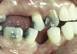
Defective restorations no longer restore the dentition to an acceptable state of form and function. Although restorations can be either temporary or permanent, no restoration can be considered truly permanent. Physical properties of restorative materials make them susceptible to alteration and deterioration. Certain materials, however, have withstood the test of time and are more readily recognized for their longevity. When properly used, gold restorations are the most durable and compatible in the oral environment. Their resistance to corrosion, nonirritating chemistry, and similarity to enamel in texture and wear resistance are qualities that other materials often lack. Amalgam is the most commonly used restorative material in dentistry because of its versatility, workability, and clinical longevity. However, masticatory forces and tooth-to-tooth contact eventually wear the occlusal margins of most amalgam restorations (Figure 36-1). Tooth-colored resin composite restorations shrink slightly during the curing process and require careful technique to obtain the desired long-lasting results. Cement materials dissolve in the oral environment, resulting in the loosening of luted restorations.
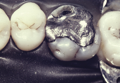
Figure 36-1 Large amalgam restoration, which has served for many years despite its poor design, exhibits defective margins.
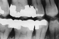
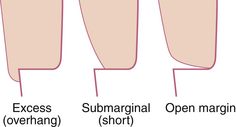
Defective restorations, however, may not always be related to the restorative material. Defectiveness of restorations also can be caused by the placement techniques of the clinician; for example, overhangs, open margins, poor contours, and open proximal contacts are the result of improper technique, poor judgment, and lack of attention to detail (Figures 36-2 and 36-3). These are avoidable defects and are not acceptable standards of care.
Esthetic Appearance
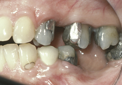
Restorative therapy is also an important factor in meeting a person’s need for a wholesome facial image. Missing, broken, or obviously decayed teeth are often the reasons individuals seek oral healthcare. Dental anomalies such as diastemas, mottled enamel, congenital tooth defects, and intrinsic tooth discolorations such as tetracycline staining also may require restorative interventions to improve appearance. One of the main disadvantages of metallic restorations has been esthetics (Figure 36-4). To maintain the esthetic appearance of restorative materials, special polishing paste is used (e.g., Soft Shine [Water Pik, Inc, Fort Collins, Colorado]).
Occlusion
The occlusal relationship influences the function and health of the dentition. Restorative treatment can be provided to improve a person’s occlusion. There are times when an occlusal adjustment, the selective reshaping of the dentition by grinding, can improve the occlusion. This is especially true when previous restorations have been poorly contoured. When teeth become misaligned because of the loss of adjacent or opposing teeth, it may be necessary to recontour them to establish a stable, functional occlusion by realigning the vector of occlusal forces to be more parallel to the long axis of the teeth (Figure 36-5). Complex restorations are necessary if this recontouring results in substantial tooth crown removal. Complete coronal restorations (crowns) and even fixed partial dentures (bridges) are necessary to restore occlusion in badly damaged dentitions.
Mastication
The most basic function of teeth is to chew food and thus begin the process of digestion. A significant number of clients indicate inadequate chewing as their chief complaint. Often frustration exists because certain favorite foods are difficult to chew. Therefore a missing tooth, defective restoration, or carious lesion can compromise an individual’s eating pleasure and nutrition.
Types of Restorations
Direct Restorations
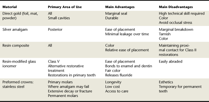
Restorations are categorized by the technique required for placement of the restorative material. These placement techniques have been classified as direct and indirect. Direct restorations are placed and formed directly in the cavity preparation. These restorations are typically placed in increments, adapted closely to the cavity walls, and shaped to the desired contours. Shaping is done with carvers when the materials are still in a soft or an unset state and with rotating instruments such as burrs and disks, used when the restorative materials are in a hard or set state. Materials used in direct restorations include moldable substances such as amalgam, resin-based composite, resin-modified glass ionomer, and direct gold. In addition, preformed stainless steel crowns that are adapted to prepared teeth using trimming techniques and crimping pliers are considered direct restorations. The restorative procedures that have been legally delegated to REF dental hygienists fall within the direct restoration category. Table 36-1 outlines the uses, advantages, and disadvantages of direct restorative materials.
Indirect Restorations
Most indirect restorations are formed on reproductions (dies) of prepared teeth. The shaping of the restoration is done by preparing the desired form in wax and then casting this form in metal or ceramic. Porcelain restorations are formed by building the restoration to shape with porcelain powder and then solidifying the mass in a special “firing” oven. Gold crowns or inlays and porcelain crowns are typical indirect restorations. Because indirect restorations are rigid, solid objects, the cavity preparation must be specially designed (tapered) to allow complete seating of the restoration at the time of permanent cementation. Computer-aided design and computer-aided manufacture (CAD-CAM) restorations are prepared chairside using a computer. With a small intraoral camera the dentist makes a digital picture of the tooth before and after preparing it. This digital image contains three-dimensional information about the size of the tooth, the defect being restored, and the adjacent teeth. The dentist then designs the desired crown or filling directly on a computer screen using CAD-CAM software. Once all the pertinent information has been entered, a tooth-colored block of ceramic material is machined by the computer.1
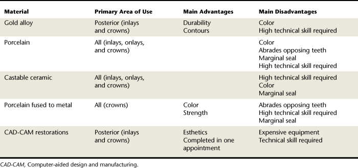
Table 36-2 outlines the uses, advantages, and disadvantages of indirect restorative materials.
Cavity Preparation
Black’s Classification System and the Complexity Classification System, presented in Chapter 14, are used to describe the type and location of dental caries and dental restorations. These systems expedite communication among those involved in the delivery of dental services.
A critical step in restoring the dentition is the preparation of the cavity. The intent of this section is to present the fundamentals of cavity preparation essential to each member of the oral health team. A basic understanding of the principles and instrumentation of cavity preparation supports the dental hygienist as a collaborative member of the team.
Principles of Cavity Preparation
Although the dental hygienist is not responsible for cavity preparation, there is value in understanding the systematic procedure of cavity preparation based on biomechanical principles. Cavity preparation typically follows these steps:
Outline Form
Establishment of an outline form provides the framework from which the remainder of the cavity preparation develops, and includes removal of weak or undermined enamel and existing defective restorative materials. The preparation margins should extend laterally beyond the decay or defect into cleansable and sound tooth structure.
Resistance and Retention Form
Obtaining the resistance and retention form involves the shaping of the internal aspects of the preparation to protect the tooth and restoration from forces that result in breakage or displacement. Primary concerns in this step are the extension and direction of cavity walls and the refinement of internal features. The retention form deals with the ability of the cavity preparation to retain the restoration; the resistance form is important for preventing lateral displacement in more complex restorations. The need for retention and resistance form for composite restorations is decreased because of the bond between enamel and composite material.
Convenience Form
In obtaining the convenience form the operator enlarges and extends the cavity preparation to enable proper instrumentation for decay removal, thereby providing an optimal final result.
Caries Removal
Depending on the severity of the carious lesion, caries may have been removed in the previous steps. However, if carious dentin remains, it is excavated to establish a disease-free environment.
Finish Enamel
At this stage the operator smoothes the walls, sharpens the margins, and removes any unsupported enamel from the margins. This process supports the desired marginal seal between the tooth structure and the restorative material.
Debridement
The final step in cavity preparation is the removal of debris and moisture that compromise the restoration, typically accomplished with the air-water syringe.
Each tooth and cavity presents a unique challenge. The severity of the carious lesion influences the complexity of the cavity preparation process. However, these fundamental steps in cavity preparation result in a preparation ready for restoration.
Atraumatic Restorative Treatment
Atraumatic restorative treatment (ART) is “a dental caries treatment procedure involving removal of soft demineralized tooth tissue using hand instruments alone, followed by restoration of the tooth with an adhesive restorative material, routinely glass ionomer.”2 ART is typically used for persons who are young, are uncooperative, or have special healthcare needs and provides caries treatment at a low cost. ART requires no anesthesia or power-driven equipment. Developed in Tanzania in the mid-1980s, it is used successfully in developing countries, where carious teeth often go untreated. In these countries, nondental personnel or primary healthcare workers provide ART; it is endorsed by the World Health Organization and the International Association for Dental Research.3 The American Academy of Pediatric Dentistry (AAPD) policy statement on interim restorative therapy (IRT) states, “The AAPD recognizes IRT as a beneficial provisional technique in contemporary pediatric restorative dentistry. IRT may be used to restore and prevent dental caries in young patients, uncooperative patients, patients with special health care needs, and situations in which traditional cavity preparation and/or placement of traditional dental restorations are not feasible.” IRT may be used for caries control in children with multiple carious lesions prior to definitive restoration of the teeth.2 IRT uses similar techniques as ART but has different therapeutic goals in that an IRT is not a definitive restoration. ART/IRT may be used to increase access to dental care by reducing costs. Currently it is not included in the scope of practice for restorative function dental hygienists in the United States.
COLLABORATIVE ROLE OF THE DENTAL HYGIENIST
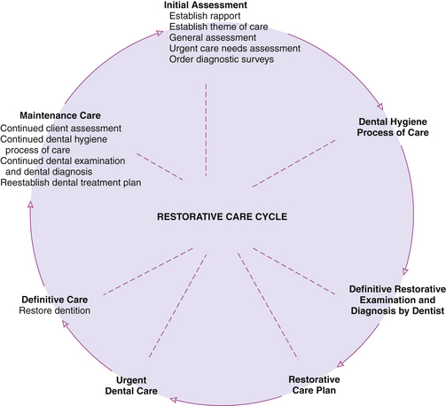
Participation of the dental hygienist in the delivery of restorative therapies affords a unique collaborative opportunity for the dentist and dental hygienist in oral healthcare delivery. The efficient use of the dentist, dental hygienist, and dental assistant allows all members of the team to contribute their expertise, ensuring high-quality, cost-effective restorative treatment. Figure 36-6 illustrates the restorative care cycle that integrates the roles of the dentist and dental hygienist throughout the delivery of restorative care.
The dental hygienist collaborates with the dentist to achieve effective restoration of the dentition. During the assessment phase of dental hygiene care, tooth damage and its cause may be identified and communicated to the dentist. In addition, based on assessment of the client’s oral hygiene status and oral health behaviors, the dental hygienist plans, implements, and evaluates oral disease prevention and health promotion strategies for the client.
Delivery of Restorative Therapies and the Dental Hygienist
Originally the dental hygienist was chiefly responsible for the prevention of oral disease, which explains why today the dental hygienist is recognized as an oral disease preventive and health promotion specialist. However, in the 1960s and 1970s it was theorized that the dental hygienist could play a significant role through the delivery of restorative therapies. It was at this time that the primary focus of the dental profession became improving the oral health of the public through the elimination and treatment of dental caries. Therefore the rationale for the initial delegation of restorative services was to provide a mechanism to respond to an expanding need and demand for dental care, making dental hygienists responsible for expanded functions. These programs were eliminated due to pressure from organized dentistry.
Because the scope of dental hygiene practice varies dramatically among states, provinces, and territories, not all educational programs prepare dental hygienists to practice in all locations.4 The dental hygienist has the legal and ethical responsibility to practice within the scope of the law at all times.
RUBBER DAM ISOLATION
Rationale
The purpose of the rubber dam is to improve the quality of restorative dental treatment via the following:
Moisture Control
The moisture-control property of the rubber dam ensures the essential dryness of the operating field.
Accessibility and Visibility
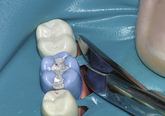
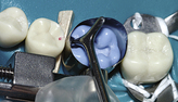
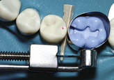
The rubber dam provides accessibility and visibility by retracting the gingival tissue surrounding the site of restoration and by retracting the cheeks, lips, and tongue from the field of operation. The background of a dark rubber dam provides excellent contrast with the tooth structure and reduces glare from the moist surfaces of the oral tissues.
Client and Practitioner Protection
The client is protected by the rubber dam because it limits the possibility of aspirating or swallowing debris and materials associated with restorative care. The rubber dam also protects oral tissues from instruments and medications that may be injurious or distasteful.
Disadvantages
The disadvantages of the rubber dam most often cited are time consumption and client objection. The efficient practitioner overcomes the perception of the procedure as time-consuming. The quality of restorations completed with the rubber dam should outweigh perceived inconvenience. Client objections can usually be overcome with education.
Contraindications
Rubber dam application may be contraindicated because of cracks or fissures of the commissures, herpetic lesions, respiratory congestion, claustrophobia, asthma, and latex allergy.
Rubber Dam Material
Features considered in the selection of rubber dam material are as follows:
The rubber dam material is typically marketed as a 5- × 5-inch child size or a 6- × 6-inch adult size latex sheet. Weights of rubber dam material are light, medium, heavy, extra heavy, and special heavy. The lighter weight, thinner dams are easier to apply because of flexibility and client comfort, whereas the heavier weight, thicker dams provide better retraction of tissues and protection from revolving instruments. Medium and heavy weights are most commonly used for restorative procedures. Rubber dam material is available in black, gray, white, green, blue, and pastels. Although color selection is based on operator preference, the main issues to consider in color selection are the contrast with the teeth and eye. Many of these materials now are pleasantly scented. Nonlatex rubber dam materials are available for clients allergic to latex.5
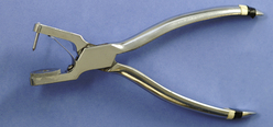
Rubber Dam Punch
The rubber dam punch, used to punch the tooth holes in the rubber dam material (Figure 36-7), typically has five or six hole sizes.
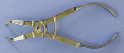
Rubber Dam Forceps
Rubber dam forceps, plierlike forceps that expand the rubber dam retainer for placement on the tooth, are used to place the rubber dam retainer (clamp) on the anchor tooth (Figure 36-8). The beaks of the forceps are placed into the holes of the retainer, and when the handles of the forceps are squeezed, the beaks are separated and the retainer is expanded. The rubber dam forceps have a locking device that may be engaged, allowing release at the handles without loss of the desired expansion.
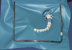
Rubber Dam Frame
The rubber dam frame is used to secure the extraoral rubber dam material during the procedure (Figure 36-9). Several styles of frames satisfy operator preference; however, the frame must be sterilizable or disposable. The most commonly used rubber dam frame is a U-shaped stainless steel frame with small projections for securing the edges of the rubber dam sheet.
Rubber Dam Retainer
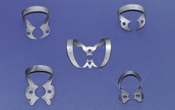
The rubber dam retainer provides intraoral stabilization of the rubber dam material by anchoring the material securely in place. The rubber dam retainer is produced in winged and wingless designs. The parts of the rubber dam retainer include the jaws, prongs, bow, and forceps holes, as follows (Figure 36-10):
 The forceps holes are the insertion point for the rubber dam forceps during the placement and removal of the retainer.
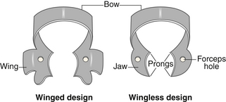
Retainer designs are identified by number. Winged and wingless retainers of the same number are identical in shape; however, the letter W is used to designate the wingless retainer. The wings of a retainer provide additional retraction of the rubber dam material away from the retainer tooth. Retainers come in numerous shapes and sizes to take into consideration the specific tooth to be retained (permanent or primary), the stage of eruption of the tooth to be retained, and the access needed for the operation (Figure 36-11). Success of rubber dam isolation depends largely on the stability of the rubber dam retainer.
Retainer Selection
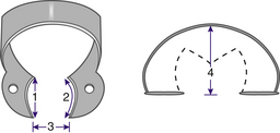
Selection of the rubber dam retainer is the next step in rubber dam application. The anchor tooth is the tooth to be retained and the most distal tooth to be isolated. Four points of consideration when selecting the retainer for the anchor tooth are as follows:
Mesiodistal width between the prongs of the retainer jaws should be slightly narrower than the mesiodistal width of the anchor tooth at the cementoenamel junction (CEJ). Mesiodistal curvature of the retainer jaws must be greater than the mesiodistal curvature of the anchor tooth at the CEJ. Faciolingual width between the prongs of the retainer jaws should be narrower than the faciolingual width of the anchor tooth at the CEJ. Bow of the retainer must arch high enough to clear the occlusal surface of the anchor tooth when the retainer is appropriately seated.Each of these criteria (illustrated in Figure 36-12) permits the correct and stable seating of the jaw prongs on the anchor tooth. Usually in the anterior aspects of the arches, the rubber dam can be successfully retained without the use of a retainer. Small pieces of rubber dam, or other devices such as wooden wedges and/or floss, can be inserted between teeth to hold the dam in position.
Rubber Dam Material Preparation
Several techniques are used to determine hole placement on the rubber dam. A rubber stamp or cardboard template can be used as a guide for marking the placement of holes for primary and permanent dentition (i.e., marks correspond to the teeth to be punched) (Figure 36-13). As the operator becomes proficient, the template is no longer needed. The tooth to receive the retainer may require a double or triple hole. The holes must be punched precisely without tags and tears, which facilitate further tearing when the dam is stretched over the tooth (Figure 36-14). For clean holes to be punched, the rubber dam punch must be well maintained and free of lodged rubber dam material. In addition, the action of punching the dam must be sharp and determined, not uncertain and hesitant.
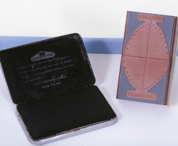
Figure 36-13 Stamp used with inkpad on rubber dam sheet marks template to punch holes for permanent and primary dentition.
(From Bird DL, Robinson DS: Torres and Ehrlich modern dental assisting, ed 9, St Louis, 2009, Saunders.)

When the dentition is normally spaced and aligned, 3 to 4 mm should be left between holes. Holes punched too close together cause stretching and inadequate seal around the tooth, whereas holes punched too far apart result in excess material and bunching (Figure 36-15).
Rubber Dam Placement Technique
Two techniques for placement of retainer and rubber dam material are as follows:
The placement of retainer and rubber dam material in a single step, which requires that the rubber dam material be placed over the bow of the retainer and then carried into its ultimate location (Figure 36-17)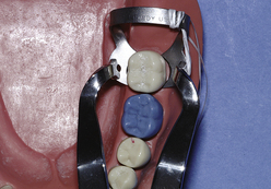
Selection of a technique is best left to operator preference. The remaining steps are identical for both techniques. The hole is then stretched to the lingual side and spread over the lingual jaw; the procedure is repeated for the facial side. The anchor tooth is now the only tooth isolated in the rubber dam (Figure 36-18). A piece of dental floss is tied to the jaw of the retainer to facilitate retrieval should the retainer break or be dislodged (Procedures 36-1 and 36-2).
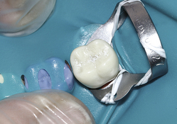
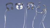
Figure 36-19 Retainer ligation progressing from lingual (left) to facial (right), and a broken ligated retainer at far right.
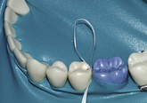
Figure 36-20 Dental floss is used to carry the septa between the teeth using the double flossing technique.
Procedure 36-1 APPLYING A RUBBER DAM
STEPS
Procedure 36-2 REMOVING A RUBBER DAM
STEPS
PERMANENT RESTORATIONS
Amalgam
Dental amalgam remains the standard restorative material for posterior teeth; this reputation is based on decades of clinical evaluation during which it has proven to be a durable material even when placed in some compromised circumstances.4 Its longevity is directly related to proper cavity preparation, attention to basic principles of manipulation, and condensation in a moisture-free environment.
Material
Dental amalgam is a compound of an alloy—a mixture of metals, mainly silver, copper, and tin—with mercury. Mercury functions to wet the alloy particles, causing the mass to undergo metallurgical changes and hardening. Early amalgams were unpredictable in their clinical longevity and particularly subject to delayed expansion (creep), corrosion, and margin deterioration. Modern amalgam materials show marked improvement in stability, strength, and margin integrity. Amalgam alloy powders are available with spheric particle shapes or with a blend of spheric and lathe-cut particles. Spheric-particle alloys handle differently when condensed into cavity preparations because rounded particles do not resist condensation pressures as do the irregularly shaped, lathe-cut particles. Because the resulting amalgam restorations from both are quite similar, selection of alloy particle type is a matter of personal choice.
Armamentarium
The following equipment is needed for placement of an amalgam restoration.
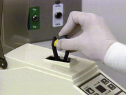
Triturator (Amalgamator)
The triturator is a mechanical device used to mix the encapsulated alloy and mercury (Figure 36-26). It is adjustable for speed and time of trituration to achieve the correct amalgam mix.
Amalgam Well
The amalgam well is a small, heavy, stainless steel dish with a cuplike recess that confines the mixed amalgam to facilitate pickup with the amalgam carrier (Figure 36-27); mixed amalgam is transferred immediately from the amalgam capsule to the amalgam well after trituration.
Amalgam Carrier
The instrument used to carry and dispense amalgam into the cavity preparation is the amalgam carrier (see Figure 36-27). The operator loads amalgam into the barrel (cylinder) by pressing the barrel tip into the amalgam mass contained in the amalgam well. When pushed, the instrument lever forces a plunger to dislodge the contained restorative material from the barrel.
Condensing Instruments
Condensing instruments are used to pack amalgam and other restorative materials firmly into a cavity preparation. There are numerous shapes and sizes of condensers (Figure 36-28). Selection is based on size and configuration of the cavity preparation and amount of material to be condensed.
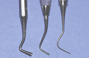
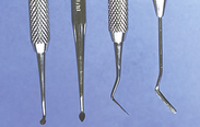
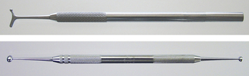
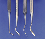
Carving and Burnishing Instruments
Carving and burnishing instruments are used to remove excess restorative material and refine the margins of the restoration. All carvers are sharp, cutting instruments. Numerous blade shapes and sizes are selected for use based on carving action to be completed and personal preference (Figure 36-29). Burnishing instruments are ball-, egg-, or beavertail-shaped instruments that give a smooth surface to the setting amalgam (Figure 36-30).
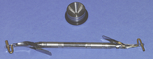
Tofflemire Matrix System
The Tofflemire matrix system is a device that reproduces proximal wall(s) removed during the preparation of the tooth. Numerous matrix techniques are available, but by far the most popular and versatile for amalgams is the Tofflemire matrix system. This system is composed of a Tofflemire retainer,matrix bands, and wedges (Figure 36-31). The Tofflemire retainer is a stainless steel mechanical device used to hold thethe matrix band. After preparation of a Class II or IV cavity prep, the matrix does the following:
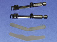
Figure 36-31 Tofflemire retainers and bands. As pictured top to bottom, straight retainer, and modified bands that fit either retainer.
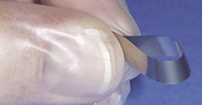
Figure 36-32 The ends of the band are placed evenly together to form a loop. The loop is tapered to permit adaptation at the gingival aspect.
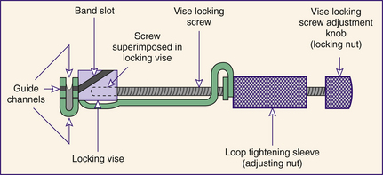
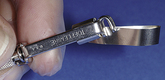
Figure 36-34 Initial placement of band in retainer slot with occlusal aspect of loop being inserted first.
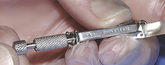
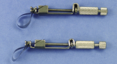
Figure 36-36 Inserted band before shaping (bottom) and band shaped to rounded form to facilitate placement (top).
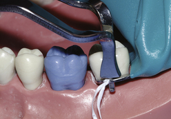
Figure 36-37 Initial placement of band over prepared tooth. Finger pressure supports lingual aspect of band.
Wedges
Wedges are typically triangular (in cross-section) pieces of wood or plastic that come in numerous sizes and adaptations. They are usually placed from the lingual side because the lingual embrasure is larger than the facial embrasure, thereby allowing a more complete wedge placement (Procedure 36-3). A properly shaped and positioned wedge does the following:
Provides slight tooth separation that supports the attainment of a positive proximal contact after removal of the matrix bandProcedure 36-3 PLACING A TOFFLEMIRE MATRIX SYSTEM
STEPS
When positioned, the guide channels of the retainer open toward the gingiva.
The loop of band should exit guide channel to allow the loop to be positioned from the preferred side of the tooth (usually the facial side).
Assuming that the seated retainer will be most commonly positioned on the facial aspect of the prepared tooth, use left channel guide for dentition in the maxillary left and mandibular right; use right channel guide for dentition in the maxillary right and mandibular left.
Trituration
Modern amalgam materials are pre-encapsulated to prevent mercury spills and provide consistent quality of mixes (Figure 36-42). Capsules contain small and large quantities for selection according to the cavity size. Within each capsule, a plastic diaphragm separates the mercury from the alloy. At the start of trituration the diaphragm ruptures, allowing amalgamation (trituration) to begin. Thorough mixing occurs within a few seconds, according to the metallurgy of the mass and the speed of the amalgamator. The operator determines the proper setting of the instrument based on the manufacturer’s recommendation, the amalgam material, and the desired mix. Following amalgamation, the mass is transferred to the amalgam well. Generally a proper mix of amalgam is shiny, homogeneous, and easily manipulated with the amalgam carrier and condensers (Figure 36-43).
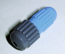
Figure 36-42 Common pre-encapsulated amalgam capsule.
(From Bird DL, Robinson DS: Torres and Ehrlich modern dental assisting, ed 9, St Louis, 2009, Saunders).
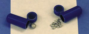
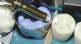
Figure 36-44 A small increment of amalgam is expressed into the proximal box of the cavity preparation.
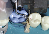
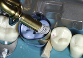

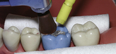
Figure 36-47 The cavity is overfilled with amalgam, and a large condenser is used to complete condensation.
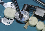
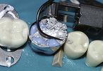
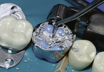
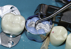
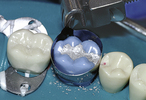

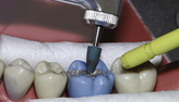
Figure 36-53 An amalgam condenser is used to stabilize the marginal ridge during the removal of the band.
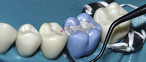
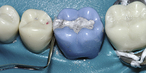
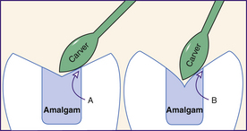
Figure 36-56 Amalgam anatomy should be carved to shallow form whenever possible. Doing so produces stronger margins (A). Thin angles seen in B will eventually fracture from occlusal stress.
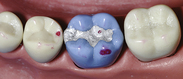
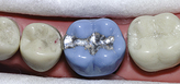
Figure 36-57 The occlusal markings show that the contact on amalgam, although present, is lighter than that on the natural tooth. As a result the operator does not need to further reduce the occlusal contact.
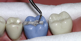
Figure 36-58 Using a stroke parallel to the margin, a sharp carver refines occlusal margins of the amalgam.
Condensing, Carving, and Burnishing Amalgam
Condensation is the process of packing the amalgam into the prepared cavity. Adequate pressure is approximately 8 lb/inch2 for lathe-cut alloys and slightly less for spheric alloys. Carving and burnishing is the process of using hand instruments to shape the freshly placed amalgam into the anatomic form that will restore tooth function (Procedure 36-4).
Procedure 36-4 PLACING AN AMALGAM RESTORATION
STEPS
Repeat procedure; have client grind the teeth for lateral movement.
Finishing and Polishing
Polished amalgam retains less oral biofilm and resists tarnish and corrosion better than unpolished amalgam. After time the amalgam hardens fully and can be polished to a high degree of smoothness; amalgam restorations must be allowed to set up for at least 24 hours prior to rotary finishing or polishing. Obtaining a smooth surface is more important than achieving a high gloss on the metallic surface; gloss is usually short-lived because of the scouring action of certain foods.
It is imperative in the polishing procedures that undue heat is not generated from rotating rubber cups and points as they contact the amalgam. Such heat can harm the pulp, leaving the tooth very sensitive. The metallurgy of the amalgam also can be adversely affected. A wet field should be maintained whenever heat generation is a possibility.
Finishing and polishing procedures vary in materials and technique. However, the first step in the procedure is to recheck the occlusion to ensure that in polishing the operator does not destroy important occlusal contacts. If the carving has left a smooth amalgam, polishing proceeds simply and rapidly. In most cases it is not realistic to attempt a polish of the proximal surface. If it is smooth, it should be left alone except for a brief “shoeshine” using wet flour pumice and dental tape. Other areas can be finished with disks, brushes, rubber cups, and points. A flour of pumice slurry and other polishing powders is used by many operators. Abrasives incorporated into special rubber polishing cups and points are also popular. After the amalgam margins are refined with a sharp carver or finishing burr, these polishing cups and points are excellent for producing a smooth metallic surface. Using a light intermittent touch and rotary speeds in the low-to-moderate range, the operator rapidly can produce an excellent finish. A periodic reshaping of the rubber points, rounded from wear, against an abrasive disk enables the operator to properly polish grooves and fossae (Procedure 36-5).
Procedure 36-5 FINISHING AND POLISHING AMALGAM RESTORATIONS
STEPS
Mercury Hygiene
Care exercised in preventing bodily harm from mercury ingestion or inhalation is termed mercury hygiene. Disregard for mercury’s toxic potential may produce injury and disease. However, in decades of use, careful handling of mercury has made its usage and dental amalgam safe.6,7
Mercury Hygiene and Dental Personnel
Individuals primarily at risk from mercury exposure are dental personnel; however, common sense provides a more than adequate margin of safety. Safety begins with well-ventilated work and storage spaces, and special filters and detectors to monitor mercury vapors. In addition, a periodic monitoring service for mercury air levels is available through dental societies. All handling of amalgam mixes should be done over a deep tray to contain loose particles and promote easy cleanup of scrap amalgam. Carpeting in the work area is not recommended because vacuuming of scrap amalgam may release mercury vapors. Scrap amalgam should be stored in airtight containers. Disposal of amalgam capsules and other contaminated materials should be done in compliance with state and local environmental and safety policies. Careful examination and cleaning of trays, amalgam wells, chair seams, and other susceptible areas may reveal small scrap particles that should be recovered safely and stored. In addition, evacuation traps should be cleaned routinely and amalgam scrap properly stored. Amalgam carriers should be checked for residual amalgam. The practice of heating a carrier over a flame to soften and remove clogged amalgam should be avoided because the released mercury fumes are toxic.
Mercury Hygiene and the Client
Significant client exposure to mercury is negated by the brevity of the dental appointment and by controlled and clean placement of the amalgam. Rubber dam isolation provides the best control of the surgical site. All scrap is readily removed when the dam is in place; thorough suctioning of particles is recommended. The combining of the mercury with the alloy prevents the release of mercury in a significant quantity.
Practitioners may routinely restore teeth with amalgam with the assurance that if they exercise reasonable care, no harm will come to the professional staff or their clients. Motivated by half-truths, alarmists have attempted to discredit the benefits of amalgam and the virtues of dentists who recommend amalgam. Claims that dentists are poisoning their clients have not been demonstrated or proven scientifically. Except in cases of client allergy to mercury, which is rare, oral healthcare professionals may continue to render fine restorative care using amalgam.
Resin-Based Composites
Resin-based composite is tooth-colored restorative material made of complex organic resin that is hardened by light activation. Many people demand the esthetics of tooth-colored restorations.
Material
Resin-based composites are a heterogeneous blend of organic resin and inorganic filler. The resin is dimethacrylate, either bisphenol A glycidyl dimethacrylate (Bis-GMA) or urethane dimethacrylate. Filler particles are silane-coated (for adhesion and coupling) barium silicate glass, quartz, or zirconium silicate; they usually are combined with very small-sized particles of colloidal silica.1 Light-cured composites include a photopolymerizable synthetic organic resin matrix. A radiopaque oxide is added to make the composite fillings visible on radiographs.8 Resin composite is often provided by manufacturers in handy dispensing devices (Figure 36-62).
Preparation
Resin composite procedures and cavity design are unique. Research has provided a means for conserving tooth structure by the discovery that retention and resistance form for resins can be created on enamel.9 This concept, known as micromechanical or enamel bonding, has become the basis for the routine placement of modern direct resin restorations and for such popular procedures as pit and fissure sealants and bonded veneers. As long as the prepared tooth presents an adequate enamel surface area, significant retention can be achieved. The enamel surface is shaped with instruments such as rotary burrs or diamonds to establish the desired design. Then controlled application of an acidic conditioning agent to the prepared enamel roughens the surface (acid etching). Thorough rinsing and forced-air drying displays the etched enamel (frosty appearance), which is ready to receive a primer and/or bonding resin and thereby retain a resin restoration.
Compared with enamel bonding, dentin bonding is far less predictable. Most cavities extend into dentin; the treatment of this tissue surface is in question. Lack of inorganic structure results in a weaker bond to organic collagen fibrils. The composition of dentin presents special challenges for those attempting to bond to it. Dentin is more organic than enamel and when instrumented leaves a surface covered with microscopically observable debris called the smear layer. This smear layer may interfere with strong bonding at the dentin-resin interface. In addition, a trace amount of moisture from the vital pulp is present on the dentin surface. Because restorative resins are incompatible with moisture (hydrophobic), numerous adhesive systems (hydrophilic) have been developed to chemically unite the resin with the moist dentin surface. Hybridization bonding is the bond between the dentin and the resin. Successes in this area continue to be made.10
Armamentarium
The following equipment is needed to place a resin composite:
Curing Light
A curing light is required to initiate polymerization of the resin matrix. The light is in the blue range and is transmitted from its electrical source via a fiberoptic bundle to the tip of a small wand that is positioned on the tooth surface (Figure 36-63). An intensity of 400 mW/cm2 is considered adequate.11
Protective Eye Shields
Protective eye shields prevent eye injury and meet the human need for protection from health risks. The wavelengths produced by the curing light have been shown to damage the retina and must be screened to protect the operator, assistant, and client. Protective shields may be handheld, attached to the wand, or incorporated in eyeglasses.
Plastic Instruments
Plastic instruments are conveniently designed to carry, shape, and mold soft (plastic) materials. They may be blunt-ended instruments or flat blades not intended for firm condensation or cutting (Figure 36-64). Selection of instruments is based on the location of the cavity preparation and personal preference. Anodized instruments have been specifically developed to facilitate placement of sticky, tooth-colored materials without adherence to the instrument.
Indications for Resin-Based Composite Restorations
Class I (Occlusal) and Class II Restorations
Client demands for natural-looking teeth have resulted in use of resin composites for restoring posterior teeth. Current generation resin composites are specifically designed for restoring either anterior or posterior teeth. Successful placement of Class II resin composite restorations still poses challenges that make some dentists hesitate to use the material as a routine restorative for these situations.12
Class II composite restorations are extremely technique sensitive. In addition to the need for very careful isolation and moisture control, manipulation of the matrix is critical. Establishing a positive proximal contact that is physiologically contoured is one of the biggest challenges facing the operator. Placement, curing, and finishing of resin composites demand four-handed dentistry at its best.
Class III and IV Restoration Placement and Finishing
Before the rubber dam is applied, shade selection is done to match the color of the composite to the dentition in which the restoration is being placed.
A typical Class III carious lesion is illustrated in Figure 36-65. The preparation is made to satisfy all principles but with emphasis on conservatism in outline form. The plastic nature of the resin material allows it to be placed under virtually no force, and specially designed delicate instruments are available for placement and finishing. In the maxillary anteriors, access is usually from the lingual direction, and care is taken to preserve the marginal ridge whenever possible. In deep restorations, dentin coverage with glass ionomer cement helps decrease microleakage and the possibility of sensitivity by bacterial invasion (Figure 36-66; Procedure 36-6).
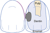
Figure 36-65 Class III carious lesion depicted. Caries is shown invading the dentin, but the cavity does not endanger the incisal corner.
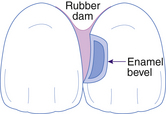
Figure 36-66 Lingual view of the completed Class III cavity preparation. The dentin is protected by a cavity liner, an enamel bevel has been placed, and the rubber dam retracts the gingiva to provide access.
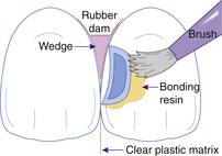
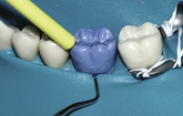
Figure 36-67 The etched enamel receiving a coating of bonding resin. A matrix separates the cavity from the adjacent tooth and is contoured and stabilized by a wedge placed interproximally.
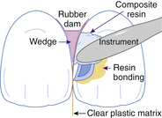
Figure 36-68 Placement of increments of resin composite into the preparation. The resin must be adapted into the recesses of the cavity and built against the matrix and cavity walls.
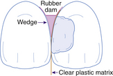
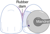
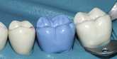
Figure 36-70 Contouring the resin composite with a disk to achieve the final form. The wedge and matrix have been removed.
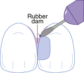
Figure 36-71 Damage to the tooth structure occurs if due caution is not exercised with the use of a burr in the finishing procedure.
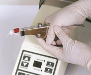
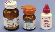
Figure 36-73 Glass ionomer products are supplied in various forms, including base and catalyst for hand mixing and triturated pre-encapsulated.
(From Bird DL, Robinson DS: Torres and Ehrlich modern dental assisting, ed 9, St Louis, 2009, Saunders).
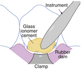
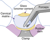
Figure 36-75 Positioning the clear cervical matrix over the cavity and expressing excess resin-modified glass ionomer at the edges of the matrix.
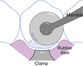
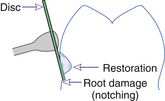
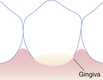
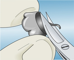
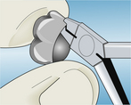
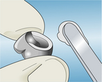
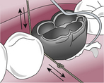
Figure 36-82 Use knotted floss and a scaler or explorer to remove excess cement after seating the crown.
Procedure 36-6 PLACING AND FINISHING A RESIN COMPOSITE RESTORATION
STEPS
Class V Restoration Placement and Finishing
A perplexing problem in restorative dentistry is the course and treatment of lesions at the gingival margin. Abrasion, erosion, dental caries, or combinations of these can create defects that are difficult to properly restore and often require isolation with special rubber dam retainers because they frequently extend into the gingival sulcus. Shade selection is accomplished before the rubber dam placement. The rubber dam is placed in a routine manner. To properly isolate the lesion, it may be necessary to retract the free gingiva to expose the gingival margin of the cavity. Several rubber dam retainers work well for this purpose. After etching, rinsing, and drying the prepared cavity, following the manufacturer’s instructions, the preparation is covered with one or more coats of a priming agent and lightly air-dried. Then the bonding resin is spread gently over the internal surface, lightly air-dried, and cured for 15 seconds. This is followed by incremental placement and curing of the resin composite. Contour can be developed by tamping the final increments into place with an instrument tip that has been dipped in bonding resin to prevent sticking to the composite. This procedure produces a smooth, contoured surface that requires a minimum of finishing. After final curing, careful shaping and polishing are accomplished with finishing burrs and disks. The gingival sulcus should be cleansed of any debris and surface coating material before the client is dismissed.
Resin-Modified Glass Ionomer
Glass ionomer cements are available as cavity liners as well as definitive restorations. Like all cements, they undergo dissolution when exposed to saliva. To compensate for the tendency to dissolve and improve their use as a restorative material, glass ionomer cements have been modified. The improved product is called resin-modified glass ionomer (RMGI). All glass ionomer dental materials release fluoride ions. As a result, recurrent caries is rarely seen at the margin of a RMGI restoration. RMGIs offer enhanced esthetics, less solubility, and greater strength than glass ionomer cements but retain some of their fluoride-release characteristics. RMGIs are an important class of materials for restoration of primary teeth.13
Materials
Glass ionomer cements are composed of aluminosilicate glass (powder) and polyalkenoic acid (liquid) that set through an acid-base reaction between the filler and the resin. A great benefit is that this material truly adheres (chemical bonding) to prepared tooth structure.11
Indications for RMGI Restorations
Indications include root caries; Class V abrasion and erosion (gingival margin) lesions in permanent teeth; ART; and Class I, II, III, and IV restorations in primary teeth (Procedures 36-7 and 36-8).
Procedure 36-7 PLACING A RESIN-MODIFIED GLASS IONOMER (RMGI) RESTORATION OF CLASS V ABRASION LESIONS
STEPS
Procedure 36-8 RESTORING A CARIOUS LESION USING ATRAUMATIC RESTORATIVE THERAPY
From Frencken JE, van Amerongen E: Phantumvanit P Manual for the atraumatic restorative treatment approach to control dental caries, ed 3, Groningen, The Netherlands, 1997, World Health Organization Collaborating Centre for Oral Health Services Research.
STEPS
Preformed Stainless Steel Crowns
Research has shown that stainless steel crowns used to restore primary molars have a greater longevity than amalgams.14,15 Some REF dental hygienists place stainless steel crowns within their scope of practice (Procedure 36-9).
Procedure 36-9 PLACING A STAINLESS STEEL CROWN
STEPS
Indications
Stainless steel preformed crowns are indicated for primary molars where an amalgam is likely to fail, for extensive caries damage involving multiple surfaces of the tooth, and after pulp or endodontic therapy.16,17 Stainless steel preformed crowns provide a suitable medium-term option when financial considerations prevent use of a permanent cast restoration in permanent molars.18
SEALERS, LINERS, AND BASES
Preserving and protecting the dental pulp are concerns in every restorative procedure on vital teeth.
Vital dentin is a dynamic tissue. At a microscopic level, it is easy to understand how a gentle stream of air may be injurious to a delicate pulp that is covered by a paper-thin thickness of dentin. Deep cavities in particular must be treated to protect the pulp from further insult; liners and bases provide such protection.19
Liners
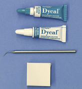
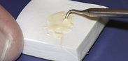
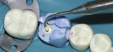
Liners are liquidlike materials applied in thin coatings (<0.5 mm) that act as cavity sealers and provide beneficial functions such as fluoride release, adhesion to tooth structure, and/or antibacterial action that promotes the health of the pulp.19 Calcium hydroxide preparations are commonly used to protect the pulp in deep cavity preparations and in situations when the pulp has been exposed, to stimulate the vital pulp to heal if the wound is small and clean. These liners are easily prepared and are usually supplied by manufacturers in small tubes (Figure 36-83). Equal amounts of agents are dispensed onto a small pad, quickly mixed, and then specifically placed on the dentin or over the pulp exposure (Figures 36-84 and 36-85). Because these materials typically do not resist compressive forces, an additional hard base material is often used for protection.
Sealers
Cavity sealers are used to seal dentinal tubules to protect the pulp from chemical irritation. Sealing of dentinal tubules is accomplished by using bonding resins or liners.19 Dentin bonding agents provide a hybridization bond formed between the restorative material and the tooth structure (hybrid layer) that has been found to better seal tubules and provide some retentive strength for resin composites when used (Figure 36-86).
Bases
Bases, materials placed to provide thermal insulation and support under metallic restorations, must be strong enough to resist occlusal forces and, in the case of amalgam, resist firm condensation. This category includes zinc phosphate, glass ionomer cements, and resin composites. Bases of zinc phosphate cement have served dentistry well, providing dependable support and insulation under metallic restorations (Figure 36-87). The rationale for its use in preventing sensitivity, however, has become questionable in recent times. Gaining a seal of the dentinal tubules to prevent microleakage is believed to be far more important in controlling postoperative sensitivity than is physical insulation. When zinc phosphate cement is used, its preparation requires attention to detail.
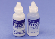
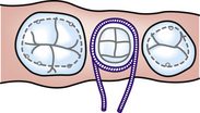
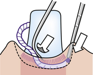
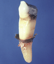
Figure 36-89 Periodontal probe holds packed cord in place while side of explorer rotates cord into place in the sulcus.
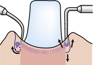
Figure 36-90 Explorer on left properly permits the cord to roll into place, but the round-ended instrument on the right permits the cord to improperly pop up on the sides.
Compared with zinc phosphate cement, glass ionomer cements require less time to prepare and bond to dentin, achieving a desirable seal. Most glass ionomer cements are available in a self-dispensing form and do not require manual mixing. However, when these cements are manually prepared, mixing and manipulation times are critical.
Resin composite materials are handled in a manner similar to glass ionomer cement bases. However, more care is required in ensuring retention because resin composites adhere only by micromechanical retention. Most of them are available in cartridge (compule) form and can be mixed mechanically in a few seconds. These may be chemical-cured or light-cured materials. For best adhesion the cavity is cleansed with a 10- to 20-second application of a conditioning agent (polyacrylic acid) to remove microscopic debris (smear layer). After rinsing and gentle drying of the cavity, the mixed cement is injected into the cavity and molded with a suitable instrument to the desired form while it is in a gel state. If chemical-cured, the material hardens in a few minutes, at which time it should be coated with a special varnish provided with the resin composite system to prevent moisture loss or gain. If the material is light-cured, the operator has time to mold it before light-activating it. Depending on the specific product, amalgam can be condensed on the set base within 4 to 10 minutes.
GINGIVAL RETRACTION
The essential first step for the fabrication of an indirect restoration is the making of an accurate impression. Gingival tissue management ensures that the margins of the preparation are appropriately captured in the impression. Gingival retraction, through the use of retraction cord around the preparation, is a critical step in achieving the desired impression. Retraction cord relaxes the gingival tissue, thereby “opening” the gingival sulcus and allowing impression material into the gingival crevice to capture the gingival margins of the preparation.
Armamentarium
Retraction Cord
Knitted gingival retraction cords have been found to work better than twined cords.20
Retraction Cord Hemostatic Agent
Retraction cord is soaked in a hemostatic agent to lubricate the cord for sulcular placement and to minimize bleeding during the impression procedure.14
Gingival Tissue Management
For any preparation for impression, the depth of the gingival margin of the preparation must be evaluated in relation to the gingival sulcus. In addition, the health and flexibility of the free gingival tissue must be assessed. Normal, healthy tissue does not require pretreatment before the tissue retraction procedure. Hemorrhagic tissue, however, may require treatment before retraction or postponement of the retraction and impression procedures. Hemorrhaging may be controlled using an astringent and coagulation liquid such as Monsel’s solution (15% ferric subsulfate) or Astringedent X (20% ferric subsulfate).
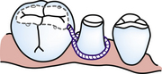
Retraction Cord Placement
Tissue retraction can be accomplished using a one-cord or two-cord retraction technique. The two-cord technique is preferred unless the depth of the sulcus or the tightness of the free gingival tissue, especially on the facial surface, does not permit placement of the second cord.15 The bottom cord, smaller in diameter, acts to control seepage and promote slight lateral displacement of the sulcular base. This cord is left in place during the impression procedure; therefore placement apical to the gingival margins of the preparation is critical. The top cord, larger in diameter, provides enhanced lateral displacement of the gingival tissue and is removed before the impression procedure. Adequate tissue retraction is achieved within 8 to 10 minutes. Each layer of cord is placed using the same technique. There are times when a small amount of anesthetic is needed for tissue retraction, such as for lingual areas of maxillary teeth. In an effort to avoid a potentially painful lingual injection, the retraction cord can be soaked in a mixture of 12.5 g of aluminum chloride crystals with 50 mL of 4% lidocaine (Procedure 36-10).
Procedure 36-10 PLACING RETRACTION CORD
STEPS
The top cord is longer and thicker than the bottom cord because it provides primary lateral tissue displacement necessary for satisfactorily allowing injection of impression material.
TEMPORARY OR INTERIM RESTORATIONS
Temporary Materials and Placement Techniques
Temporary Stopping
Temporary stopping is a thermoplastic compound that is quickly and easily prepared and placed (Figure 36-92); it is best used to seal small, shallow cavities requiring temporary restoration for periods of not more than 2 weeks.
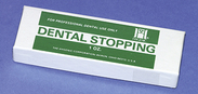
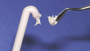
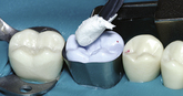
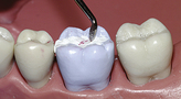
The placement of temporary stopping requires that the end of a stick of material be slowly warmed over an alcohol flame until softened, then allowed to cool until it can be handled by the operator. Small increments are rapidly molded in the fingers and positioned on the tip of a placing instrument (Figure 36-93). These increments are rapidly and firmly packed into the cavity until the material fills the preparation. Minor shaping of the restoration to restore the tooth to the original occlusion or anatomy is done with a warm, not hot, instrument tip.
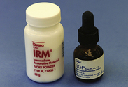
Reinforced Zinc Oxide with Eugenol
Reinforced zinc oxide with eugenol readily restores intermediate-size cavities that require a more durable material; it is prepared with a mixture of zinc oxide powder and eugenol liquid (Figure 36-94). The insulating properties of the hardened zinc oxide mass and the obtundent effect of the eugenol result in a material that protects the vital pulp against chemical and thermal insults. Reinforced zinc oxide with eugenol is relatively easy to prepare and place and is reliable for interim periods of a few months.
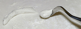
The powder and liquid are mixed on a nonabsorbent pad according to manufacturer’s instructions. Firm pressure on the spatula is needed to thoroughly mix the material. Properly mixed, the material is thick and claylike. The material is then rolled with the fingertips (on the pad) into a cylindric form. Increments can be pinched off the end of the mass with a placing instrument and firmly packed into the preparation until it is full (Procedure 36-11).
Procedure 36-11 PREPARING REINFORCED ZINC OXIDE AND EUGENOL TEMPORARY RESTORATIONS (CLASS II CAVITY PREPARATION)
STEPS
Custom-Made Acrylic Resin
The custom-made acrylic resin temporary restoration is recommended for complex restorations such as inlays and partial or complete veneer crowns; the technique permits the reproduction of the tooth anatomy. A limitation of this technique is that the tooth restored must be intact enough to allow adequate retention of the temporary restoration. However, the final product is durable, smooth, and comfortable and can serve for several months.
Preformed Stock Crown (Metal or Polycarbonate)
Preformed stock crowns make handy and useful temporary crowns. These crown forms are readily trimmed and modified for fit and provide a satisfactory alternative to the custom-made acrylic crown previously discussed. The final product is extremely durable; however, it is a compromise in both form and shape. These temporary crowns are usually comfortable for the client.
Luting Agents
Indirect restorations are fabricated in the dental laboratory on dies made from impressions of prepared teeth. These restorations include crowns and inlays made of rigid substances such as metal, cast ceramic, or porcelain. When these restorations are completely seated, all margins should intimately fit. However, between the restoration and the cavity walls exists a minute space filled with a luting agent (cement) that, when set, prevents the indirect restoration from loosening. Dislodging forces of occlusion and mastication are resisted by this firm interface of cement. Without a proper luting agent, castings leak, loosen, and fail.
Zinc Phosphate Cement
Zinc phosphate, the oldest of the luting agents, remains the standard for cementation of most indirect restorations, especially partial coverage castings and full crown metal restorations. Because zinc phosphate is quite acidic, vital pulps are often protected by a varnish barrier between the cement and dentin.
Glass Ionomer Cement
The chemical adhesion of this material to the tooth surface and relative ease in handling has led to its popularity as a luting agent. When compared with zinc phosphate, it is less acidic and more compatible with the dental pulp. It inhibits recurrent caries through the slow release of fluoride. The mixing and working times for the chemical-cured glass ionomer cement are quite short, and thus the dental team must exercise expediency when luting restorations with glass ionomer cement. Most cements of this type can be prepared on a nonabsorbent paper pad, in accordance with manufacturer’s instructions. The luting cement is mixed to a much less viscous state than the glass ionomer cement base material or restorative material previously described.
Resin Cements
Chemical-cured resin cements are used when strength of bonding is needed and light activation is not possible (e.g., cementation of cast post and cores and Maryland bridges). The bond strength of resin cements is much greater than that of other cements, but handling characteristics are more sensitive and the working time is shorter. The modified resin cements are also useful for cementation of complete metal or metal ceramic crowns to be placed on tooth preparations with minimal retentive features. Dual-cured resin cements are the cementing agents of choice for all porcelain or ceramic restorations (veneers, inlays, onlays, complete veneer crowns).
Zinc Oxide and Eugenol
Primary materials for temporary cementation of restorations are preparations of zinc oxide with eugenol. These materials vary in hardness and retaining abilities and are selected accordingly. Temporary cements are most commonly contained in small tubes and have a fluid-paste consistency. Equal amounts of base and catalyst are expressed onto a small pad and rapidly mixed. The cement is applied to cover the inside of the restoration (usually a temporary restoration), which is then seated and held in place until the cement has hardened. Excess, hardened cement is removed with an instrument such as a periodontal curet or explorer.
EVALUATION
The restorative care cycle demands ongoing assessment and evaluation. Appropriateness of treatment must be judged from the perspectives of both the professional and the client. The professional must be responsible for appropriateness and technical quality of the restoration; the client should be prepared to address issues such as comfort, function, and appearance.
DOCUMENTATION
Restorative treatment must be accurately documented in the client’s record, including all procedures in the delivery of restorative treatment. Documentation may include but is not limited to the teeth and locations of restoration, anesthetic agents and medications, tooth isolation procedures, restorative materials, complications, and client education. When restorative treatment dictates special precautions, specific details should be recorded. For example, teeth restored with glass ionomer cement should be protected against dehydration.
MAINTENANCE OR CONTINUED CARE
Assessment is an ongoing component of restorative care. During maintenance care, the dental hygienist thoroughly reviews the health, dental, and pharmacologic histories of the client, assesses the outcomes of dental hygiene and dental care, and evaluates the client’s current oral health status. These assessments, regularly communicated to the dentist, support the continued plan of care.
CLIENT EDUCATION TIPS
Advise clients of importance of oral plaque control in maintaining the integrity of dental restorations. Explain that professional maintenance care, on a regular basis, is necessary to monitor status of restorations and oral health. Explain that poor oral hygiene contributes to necessary replacement and extension of existing restorations. Explain that the maximum strength of amalgam occurs many hours after placement; efore care is required when chewing with force on newly placed amalgam restorations. Explain that for best esthetics, whitening of teeth should be done before restoration because tooth-colored restorations are not affected by the whitening products. Explain that use of stannous fluoride and 0.12% chlorhexidine mouth rinse can stain tooth-colored restorations. Explain that food and other substances will stain tooth-colored restorations. (e.g., coffee, tea, red wine, fruit juices, medications, and tobacco). Explain that temporary restorations are placed for short-term, interim comfort of the client and protection of the cavity preparation. Permanent follow-up treatment is necessary.LEGAL, ETHICAL, AND SAFETY ISSUES
The dental hygienist must practice legally within the scope authorized by state law. Carefully check statutes to determine scope of practice in restorative dental procedures. Overhangs, open margins, short margins, poor contours, and open proximal contacts are avoidable defects and not acceptable standards of care. The final plan of restorative dental treatment must reflect agreement between the dentist and an educated, informed client. When the dentist is unable to render the restorative service of choice, there is an ethical obligation to refer the client to a dentist who has the necessary skills and expertise.KEY CONCEPTS
Restorative therapies restore the dentition to a state of health, support the maintenance of health, and provide esthetic modifications to the dentition. The rubber dam is an isolation technique used to control moisture, improve accessibility and visibility, protect the client and operator, and manage the client. Resin composite is a tooth-colored restorative material used for anterior restorations and posterior restorations with consideration. Glass ionomer cements and resin-modified glass ionomer cements release fluoride ions and are well suited for restoration of root caries, Class V abrasion and erosion lesions, and Class I and II caries on primary teeth. Stainless steel preformed crowns are the most durable restoration for primary molars with multisurface caries. Gingival retraction is essential for making an accurate impression of gingival margins of an indirect restoration. Temporary (interim) restorations ensure client comfort, provide tooth and gingival protection, and prevent tooth movement during the period between initial and final tooth preparation and restoration placement.CRITICAL THINKING EXERCISES
Profile: A very well-groomed 53-year-old professional woman has signs of root caries on teeth 29, 28, 8, 9, and 27. She has lost an MOD amalgam on tooth 30 and an MO amalgam on tooth 20. She states she has some concerns about putting any more mercury in her mouth and wonders if the new tooth-colored fillings are as good as silver fillings.
Chief Complaint: “My teeth have become very sensitive, and I have lost two fillings. I can’t decide if I should have silver fillings put back in or if I should go with white fillings.”
Health and Dental History: Client is in excellent general health, is single, and lives alone. She currently takes no medications, and her blood pressure is within normal limits. Radiographic and clinical findings reveal no additional dental caries; however, generalized gingivitis, moderate plaque, calculus, and tobacco stain are present.
Oral Health Behavior Assessment: Client states that she brushes her teeth once a day, does not use floss, and visits the dentist once every 2 years.
Supplemental Notes: She has dental insurance, demonstrates a sincere interest and motivation to maintain her teeth, but states she would prefer to not wear that piece of rubber when the dentist fills her teeth.
ACKNOWLEDGMENTS
The authors acknowledge Cheryl A. Cameron and Richard B. McCoy for their past contributions to this chapter.
The authors also wish to acknowledge James R. Clark for the photography provided for this chapter.
Refer to the Procedures Manual where rationales are provided for the steps outlined in the procedures presented above.
1. Strub J.R., Rekow E.D., Witkowski S. Computer-aided design and fabrication of dental restorations: current systems and future possibilities. J Am Dent Assoc. 2006;137:1289.
2. Academy of Pediatric Dentistry Council on Clinical Affairs: Policy on interim therapeutic restorations (ITR). Available at: http://www.aapd.org/media/Policies_Guidelines/P_ITR.pdf. Accessed November 26, 2008.
3. van Gemert-Schriks M.C., van Amerongen W.E., ten Cate J.M., Aartman I.H. Three-year survival of single- and two-surface ART restorations in a high-caries child population. Clin Oral Investig. 2007;11:337.
4. American Dental Hygienists’ Association (ADHA): ADHA website. Available at: www.adha.org. Accessed September 2008.
5. Corbin S.B., Kohn W.G. The benefits and risks of dental amalgam: current findings reviewed. J Am Dent Assoc. 1994;125:381.
6. American Dental Association Council on Scientific Affairs and Council on Dental Benefit Programs. Statement on posterior resin-based composites. J Am Dent Assoc. 1998;129:1627.
7. American Dental Association (ADA) Division of Science on Behalf of the ADA Council on Scientific Affairs. Dental product spotlight: resin-based composites. J Am Dent Assoc. 2003;134:510.
8. Buonocore M.G. A simple method of increasing adhesion of acrylic filling materials to enamel surfaces. J Dent Res. 1955;34:849.
9. Perdigao J. New developments in dental adhesion. Dent Clin North Am. 2007;51:333.
10. Martin F.E. A survey of the efficiency of visible light curing units. J Dent. 1998;26:239.
11. Christensen G.J. Overcoming the challenges of Class II resin-based composites. J Am Dent Assoc. 2006;137:1021.
12. Croll T.P., Bar-Zion Y., Segura A. Clinical performance of resin-modified glass ionomer cement restorations in primary teeth: a retrospective evaluation. J Am Dent Assoc. 2001;132:1110.
13. Braff M.H. A comparison between stainless steel crowns and multisurface amalgams in primary molars. ASDC J Dent Child. 1975;42:474.
14. Dawson L.R., Simon J.F., Taylor P.P. Use of amalgam and stainless steel restorations for primary molars. ASDC J Dent Child. 1981;48:420.
15. Nash D.A. The nickel-chromium crown for restoring posterior primary teeth. J Am Dent Assoc. 1981;102:44.
16. Brook A.H., King N.M. The role of stainless steel crowns, part 1. Properties and techniques. Dent Update. 1981;9:25.
17. Croll T.P. Permanent molar stainless steel crown restoration. Quintessence Int. 1987;18:313.
18. Hilton T.J., Summitt J.B. Pulpal considerations. In Summitt J.B., editor: Fundamentals of operative dentistry: a contemporary approach, ed 2, Chicago: Quintessence, 2001.
19. Schmitt S.M., Brown F.H. A rationale for management of the dentogingival junction. J Prosthet Dent. 1989;62:381.
20. Johnson W. Hemostatic agent ingredients. Oper Dent. 1998;23:215.
Visit the  website at http://evolve.elsevier.com/Darby/Hygiene for competency forms, suggested readings, glossary, and related websites..