Occlusal and Localization Techniques
After completion of this chapter, the student will be able to do the following:
• Define the key terms associated with occlusal and localization techniques
• Describe the purpose of occlusal examination
• List the uses of occlusal examination
• Describe the patient and equipment preparations that are necessary before using the occlusal technique
• State the recommended vertical angulations for the following maxillary occlusal projections: topographic, lateral (right or left), and pediatric
• State the recommended vertical angulations for the following mandibular occlusal projections: topographic, cross-sectional, and pediatric
• State the purpose of localization techniques
• Describe the buccal object rule
• Describe the right-angle technique
• List the patient and equipment preparations that are necessary before using the buccal object rule or the right-angle technique
• Describe receptor placements for the buccal object rule and compare the resulting images
• Describe receptor placements for the right-angle technique and compare the resulting images
In addition to mastering periapical and interproximal examination techniques, the dental radiographer must also master occlusal and localization techniques. Before the dental radiographer can use these important techniques, an understanding of the basic concepts, patient preparation, equipment preparation, and receptor placement procedures is necessary.
The purpose of this chapter is to present basic concepts and to describe patient preparation, equipment preparation, and receptor placement procedures for both occlusal and localization techniques.
Occlusal Technique
The occlusal technique is used to examine large areas of the maxilla or the mandible. Before the dental radiographer can use the occlusal technique, a thorough understanding of basic concepts is necessary. In addition, a knowledge of step-by-step procedures is required.
Basic Concepts
Before describing the principles of the occlusal technique, a number of basic terms must be defined, as follows:
Occlusal surfaces: Chewing surfaces of posterior teeth
Occlusal examination: A type of intraoral radiographic examination to inspect large areas of the maxilla or the mandible on one image.
Occlusal technique: Method used to expose a receptor in occlusal examination
Occlusal receptor: In the occlusal technique, a size 4 intraoral receptor is used. The receptor is so named because the patient “occludes,” or bites, on the entire receptor. Size 4 receptors are the largest size of intraoral receptors, measuring 3 × 2.25 inches. In adults, size 4 receptors are used in occlusal examination. In children, however, size 2 receptors are typically used.
Purpose and Use
The occlusal technique is a supplementary radiographic technique that is usually used in conjunction with periapical or bite-wing images. The occlusal technique is used when large areas of the maxilla or the mandible must be visualized. The occlusal image is preferred when the area of interest is larger than a periapical receptor may cover or when the placement of intraoral receptors is too difficult for the patient. Occlusal imaging can be used for the following purposes:
• To locate retained roots of extracted teeth
• To locate supernumerary (extra), unerupted, or impacted teeth
• To locate foreign bodies in the maxilla or the mandible
• To locate salivary stones in the duct of the submandibular gland
• To locate and evaluate the extent of lesions (e.g., cysts, tumors, malignancies) in the maxilla or the mandible
• To evaluate the boundaries of the maxillary sinus
• To evaluate fractures of the maxilla or the mandible
• To aid in the examination of patients who cannot open their mouths more than a few millimeters
• To examine the area of a cleft palate
• To measure changes in the size and shape of the maxilla or the mandible
Step-by-Step Procedures
Step-by-step procedures for the exposure of occlusal images include patient preparation, equipment preparation, and receptor placement methods. Before exposing any occlusal receptors, infection control procedures (as described in Chapter 15) must be completed.
Patient Preparation
After completion of infection control procedures and preparation of the treatment area and supplies, the patient should be seated. After seating the patient, the dental radiographer must prepare the patient for exposure of receptors (Procedure 21-1).
Equipment Preparation
After patient preparation, equipment must also be prepared before the exposure of any receptors (Procedure 21-2).
Maxillary Occlusal Projections
Three maxillary occlusal projections are commonly used: (1) topographic, (2) lateral (right or left), and (3) pediatric.
Topographic Projection: The maxillary topographic occlusal projection is used to examine the palate and the anterior teeth of the maxilla (Procedure 21-3).
PROCEDURE 21-3 Maxillary Topographic Occlusal Projection (Figure 21-1)
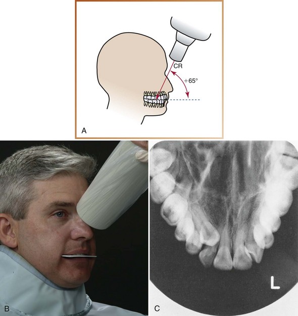
FIGURE 21-1 A, The central ray (CR) is directed at +65 degrees vertical angulation to the plane of the receptor. B, Relationship of the receptor and the position-indicating device (PID). C, Maxillary topographic occlusal projection. (A and C, Courtesy of Carestream Health Inc., Rochester, NY.)
1. Position the patient such that the maxillary arch is parallel to the floor.
2. Position a size 4 film with the white side facing the maxilla and the long edge in a side-to-side direction. Insert the receptor into the patient’s mouth, placing it as far posteriorly as the patient’s anatomy permits.
3. Instruct the patient to bite gently on the receptor, retaining the position of the receptor in an end-to-end bite.
4. Position the position-indicating device (PID) such that the central ray is directed through the midline of the arch toward the center of the receptor.
5. Position the PID such that the central ray is directed at +65 degrees vertical angulation toward the center of the receptor. The top edge of the PID is placed between the patient’s eyebrows on the bridge of the nose.
Lateral (Right or Left) Projection: The maxillary lateral occlusal projection is used to examine the palatal roots of molar teeth. It may also be used to locate foreign bodies or lesions in the posterior maxilla (Procedure 21-4).
PROCEDURE 21-4 Maxillary Lateral Occlusal Projection (Figure 21-2)
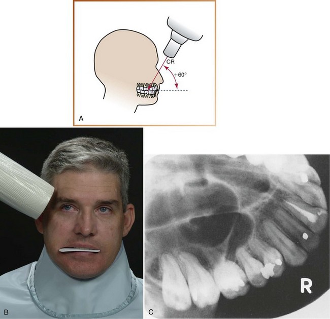
FIGURE 21-2 A, The central ray (CR) is directed at +60 degrees vertical angulation to the plane of the receptor. B, Relationship of the receptor and the position-indicating device (PID). C, Maxillary lateral occlusal projection. (A and C, Courtesy of Carestream Health Inc., Rochester, NY.)
1. Position the patient such that the maxillary arch is parallel to the floor.
2. Position a size 4 film with the white side facing the maxilla and the long edge in a front-to-back direction. Insert the receptor into the patient’s mouth, and place it as far posteriorly as the patient’s anatomy permits. Shift the receptor to the side (right or left) of the area of interest. The long edge of the receptor should extend approximately a  inch beyond the buccal surfaces of posterior teeth.
3. Instruct the patient to bite gently on the receptor, retaining the position of the receptor in an end-to-end bite.
4. Position the position-indicating device (PID) such that the central ray is directed through the contact areas of interest.
5. Position the PID such that the central ray is directed at +60 degrees vertical angulation toward the center of the receptor. The top edge of the PID is placed above the corner of the patient’s eyebrow.
Pediatric Projection: The maxillary pediatric occlusal projection is used to examine the anterior teeth of the maxilla and is recommended for use in children 5 years or younger (Procedure 21-5).
PROCEDURE 21-5 Maxillary Pediatric Occlusal Projection (Figure 21-3)
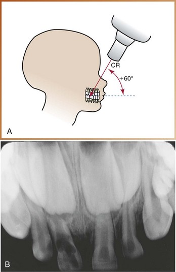
FIGURE 21-3 A, The central ray (CR) is directed at +60 degrees vertical angulation to the plane of the receptor. B, Maxillary pediatric occlusal projection.
1. Position the child such that the maxillary arch is parallel to the floor.
2. Position a size 2 film with the white side facing the maxilla and the long edge in a side-to-side direction. Insert the receptor into the child’s mouth.
3. Instruct the child to bite gently on the receptor, retaining the position of the receptor in an end-to-end bite.
4. Position the position-indicating device (PID) such that the central ray is directed through the midline of the arch toward the center of the receptor.
5. Position the PID such that the central ray is directed at +60 degrees vertical angulation toward the center of the receptor. The top edge of the PID is placed between the child’s eyebrows on the bridge of the nose.
Mandibular Occlusal Projections
Three mandibular occlusal projections are commonly used: (1) topographic, (2) cross-sectional, and (3) pediatric.
Topographic Projection: The mandibular topographic occlusal projection is used to examine the anterior teeth of the mandible (Procedure 21-6).
PROCEDURE 21-6 Mandibular Topographic Occlusal Projection (Figure 21-4)
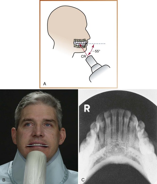
FIGURE 21-4 A, The central ray (CR) is directed at −55 degrees vertical angulation to the plane of the receptor. B, Relationship of the receptor and the position-indicating device (PID). C, Mandibular topographic occlusal projection. (A and C, Courtesy of Carestream Health Inc., Rochester, NY.)
1. Position the patient such that the mandibular arch is parallel to the floor.
2. Position a size 4 film with the white side facing the mandible and the long edge in a side-to-side direction. Insert the receptor into the patient’s mouth, placing it as far posteriorly as the patient’s anatomy permits.
3. Instruct the patient to bite gently on the receptor, retaining the position of the receptor in an end-to-end bite.
4. Position the position-indicating device (PID) such that the central ray is directed through the midline of the arch toward the center of the receptor.
5. Position the PID such that the central ray is directed at −55 degrees vertical angulation toward the center of the receptor. The PID should be centered over the patient’s chin.
Cross-Sectional Projection: The mandibular cross-sectional occlusal projection is used to examine the buccal and lingual aspects of the mandible. It is also used to locate foreign bodies or salivary stones in the region of the floor of the mouth (Procedure 21-7).
PROCEDURE 21-7 Mandibular Cross-Sectional Occlusal Projection (Figure 21-5)
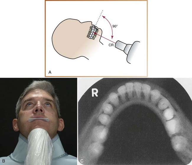
FIGURE 21-5 A, The central ray (CR) is perpendicular (90 degrees vertical angulation) to the plane of the receptor. B, Relationship of receptor and PID. C, Mandibular cross-sectional occlusal projection. (A and C, Courtesy of Carestream Health Inc., Rochester, NY.)
1. Recline the patient, and position him or her such that the mandibular arch is perpendicular to the floor.
2. Position a size 4 film with the white side facing the mandible and the long edge in a side-to-side direction. Insert the receptor into the patient’s mouth as far posteriorly as the patient’s anatomy permits.
3. Instruct the patient to bite gently on the receptor, retaining the position of the receptor in an end-to-end bite.
4. Position the position-indicating device (PID) such that the central ray is directed through the midline of the arch toward the center of the receptor.
5. Position the PID such that the central ray is directed at 90 degrees vertical angulation toward the center of the receptor. The PID should be centered approximately 1 inch below the patient’s chin.
Pediatric Projection: The mandibular pediatric occlusal projection is used to examine the anterior teeth of the mandible and is recommended for use in children 5 years or younger (Procedure 21-8).
PROCEDURE 21-8 Mandibular Pediatric Occlusal Projection (Figure 21-6)
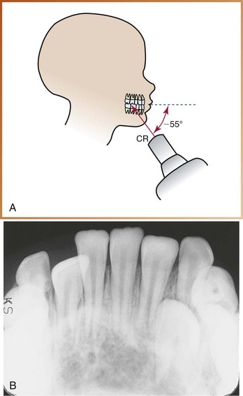
FIGURE 21-6 A, The central ray (CR) is directed at −55 degrees vertical angulation to the plane of the receptor. B, Mandibular pediatric occlusal projection.
1. Position the child such that the mandibular arch is parallel to the floor.
2. Position a size 2 film with the white side facing the maxilla and the long edge in a side-to-side direction. Insert the receptor into the child’s mouth.
3. Instruct the child to bite gently on the receptor, retaining the position of the receptor in an end-to-end bite.
4. Position the position-indicating device (PID) such that the central ray is directed through the midline of the arch toward the center of the receptor.
5. Position the PID such that the central ray is directed at −55 degrees vertical angulation. The PID should be centered over the child’s chin.
Vertical Angulations
The recommended vertical angulations for all maxillary and mandibular occlusal exposures are summarized in Table 21-1.
Localization Techniques
A localization technique is a method used to locate the position of a tooth or an object in the jaws. Before the dental radiographer can use localization techniques, a thorough understanding of basic concepts is necessary. In addition, a knowledge of step-by-step procedures is required.
Basic Concepts
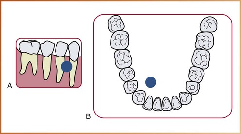
The dental radiograph is a two-dimensional picture of a three-dimensional object. A radiographic image depicts an object in superior–inferior and anterior–posterior relationships. The dental radiograph, however, does not depict the buccal–lingual relationship, or the depth, of an object. In dentistry, it may be necessary to establish the buccal–lingual position of a structure such as a foreign object or an impacted tooth within the jaws. Localization techniques can be used to obtain this three-dimensional information. Localization techniques may be used to locate the following:
Types of Localization Techniques
Two basic techniques are used to localize objects: (1) the buccal object rule and (2) the right-angle technique.
Buccal Object Rule: The buccal object rule governs the orientation of structures portrayed in two radiographs exposed at different angulations. Using proper technique and angulation, a periapical or bite-wing receptor is exposed; then, after changing the direction of the x-ray beam, a second periapical or bite-wing receptor is exposed using a different horizontal or vertical angulation. For example, a different horizontal angulation is used when trying to locate vertically aligned images (e.g., teeth treated with root canal therapy), whereas a different vertical angulation is used when trying to locate a horizontally aligned image (e.g., the mandibular canal). After the two exposures are completed, the images are compared with each other.
When the dental structure or object seen in the second image appears to have moved in the same direction as the shift of the position-indicating device (PID), the structure or object in question is positioned to the lingual (Figure 21-7). For example, if the horizontal angulation is changed by shifting the PID mesially, and the object in question moves mesially on the image, then the object lies to the lingual (lingual = same).
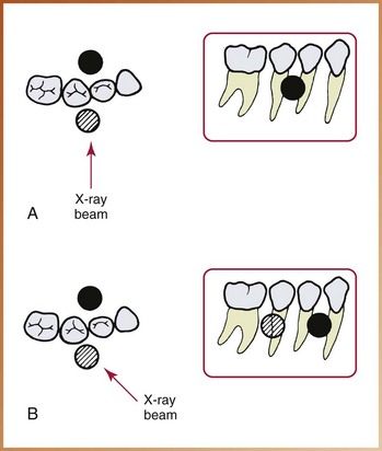
FIGURE 21-7 Buccal and lingual objects shift positions when the direction of the x-ray beam is changed. A, Buccal (cross-hatched circle) and lingual (black circle) objects are superimposed in the original radiograph. B, If the tubehead is shifted in a mesial direction, the buccal object moves distally, and the lingual object moves mesially (same direction = lingual; opposite direction = buccal). (Redrawn from Haring JI, Lind LJ: Radiographic interpretation for the dental hygienist, Philadelphia, 1993, Saunders.)
Conversely, when the dental structure or object seen in the second image appears to have moved in the direction opposite the shift of the PID, the structure or object in question is positioned to the buccal (Figure 21-8). For example, if the horizontal angulation is changed by shifting the PID distally, and the object in question moves mesially on the image, then the object lies to the buccal (buccal = opposite ).
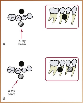
FIGURE 21-8 Buccal and lingual objects shift positions when the direction of the x-ray beam is changed. A, Buccal (cross-hatched circle) and lingual (black circle) objects are superimposed in the original radiograph. B, If the tubehead is shifted in a distal direction, the buccal object moves mesially, and the lingual object moves distally (same direction = lingual; opposite direction = buccal). (Redrawn from Haring JI, Lind LJ: Radiographic interpretation for the dental hygienist, Philadelphia, 1993, Saunders.)
The mnemonic “SLOB” can be used to remember the buccal object rule, as follows:

In other words, when the two images are compared, the object that lies to the lingual appears to have moved in the same direction as the PID, and the object that lies to the buccal appears to have moved in the opposite direction as the PID.
Right-Angle Technique: The right-angle technique is another rule for the orientation of structures seen in two images. One periapical receptor is exposed using the proper technique and angulation to show the position of the object in superior–inferior and anterior–posterior relationships. Next, an occlusal receptor is exposed directing the central ray at a right angle, or perpendicular (90 degrees), to the receptor. The occlusal image shows the object in buccal–lingual and anterior–posterior relationships. After the two receptors have been exposed and processed, the images are compared with each other to locate the object in three dimensions (Figure 21-9). This technique is primarily used for locating objects in the mandible.
Step-by-Step Procedures
Step-by-step procedures for localization techniques include patient and equipment preparations and receptor placements and comparisons.
Patient and Equipment Preparations
Before exposing receptors using localization techniques, infection control procedures (as described in Chapter 15) and patient and equipment preparations (described earlier in this chapter) must be completed.
Receptor Placements and Image Comparisons
Example
The buccal object rule can be used to determine the position of a tooth treated endodontically with gutta percha (an endodontic filling material) in a maxillary second premolar (Figure 21-10).
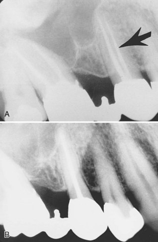
FIGURE 21-10 A, Note the two root canals filled with gutta percha in the maxillary second premolar (arrow). B, The PID was shifted in a mesial direction, so the gutta percha moved in a distal direction. The gutta percha in the original root labeled by the arrow is located on the buccal. (Radiographs courtesy of Dr. Robert Jaynes, Assistant Professor, Oral Radiology Group, The Ohio State University College of Dentistry. From Haring JI, Lind LJ: Radiographic interpretation for the dental hygienist, Philadelphia, 1993, Saunders.)
1. Position the patient in such a way that the maxillary arch is parallel to the floor.
2. Expose one molar periapical receptor using proper technique and angulation.
3. Shift the position-indicating device (PID) in a mesial direction, and expose another premolar periapical receptor.
4. In the second image, when the PID was moved in a mesial direction, the gutta percha moved in the opposite direction. Therefore the location of the gutta percha is in the root that lies to the buccal (buccal = opposite).
Example
The buccal object rule can be used to determine the location of an impacted supernumerary (extra) tooth (Figure 21-11).
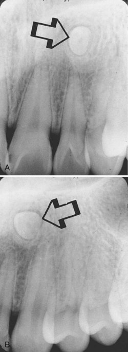
FIGURE 21-11 A, Note the impacted tooth (arrow). B, The position-indicating device (PID) was shifted in a distal direction, so the tooth moved in a distal direction. The tooth is located lingual to the adjacent teeth. (Radiographs courtesy of Dr. Robert Jaynes, Assistant Professor, Oral Radiology Group, The Ohio State University College of Dentistry.)
1. Position the patient in such a way that the maxillary arch is parallel to the floor.
2. Expose one central–lateral incisor periapical receptor using proper technique and angulation.
3. Shift the position-indicating device (PID) in a distal direction, and expose the canine periapical receptor.
4. In the second image, when the PID was moved in a distal direction, the impacted tooth moved in the same direction. Therefore the tooth lies to the lingual (lingual = same).
Example
The right-angle technique can be used to determine the position of a radiopaque foreign object (Figure 21-12).
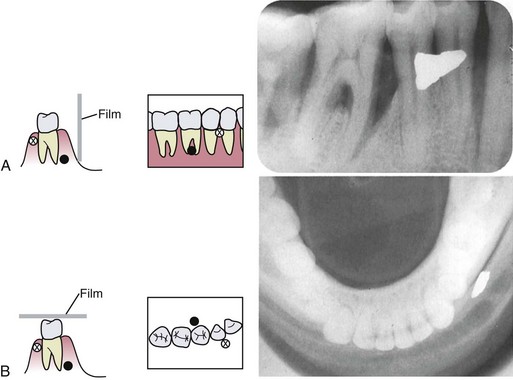
FIGURE 21-12 Right-angle localization technique. Two receptors are exposed at right angles to each other to identify the location of a foreign object. The periapical radiograph (A) will demonstrate the superior–inferior and anterior–posterior positions of objects. A cross-sectional mandibular occlusal radiograph (B) will demonstrate the anterior–posterior and buccal–lingual positions. These two radiographic views will demonstrate all three dimensions of an area, and the location of objects can thus be identified. (Redrawn from Olson SS: Dental radiography laboratory manual, Philadelphia, 1995, Saunders.)
1. Position the patient in such a way that the maxillary arch is parallel to the floor.
2. Expose one periapical receptor using proper technique and angulation.
3. Expose an occlusal receptor, and direct the central ray perpendicular to the receptor.
4. In the occlusal image, the radiopaque foreign object is located on the buccal to side of the mandible.
Buccal Object Rule and Right-Angle Technique:
Example
The patient presents to the endodontist for root canal therapy on tooth #30. A small piece of clipped orthodontic wire, which was accidentally left behind during previous treatment and was eventually covered by the buccal mucosa, is revealed by dental imaging. The buccal object rule is used to localize the orthodontic wire; the right-angle technique is also used to confirm the location, as follows:
1. Position the patient in such a way that the maxillary arch is parallel to the floor.
2. Expose one periapical image of tooth #30. A radiopaque artifact will be seen near the furcation area (Figure 21-13, A).
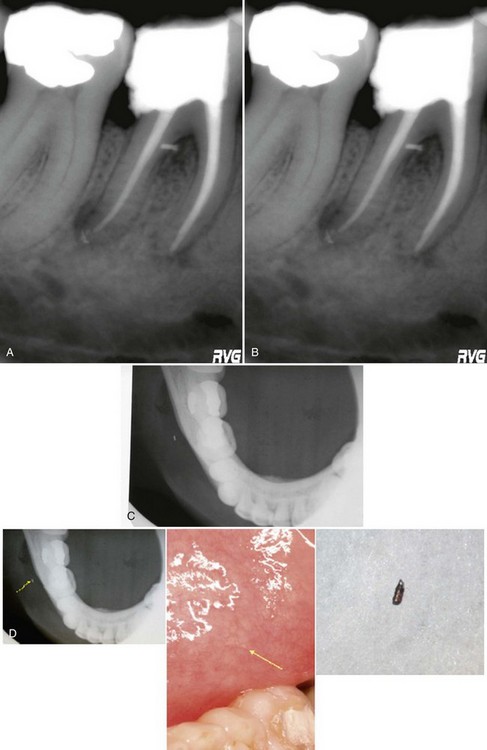
FIGURE 21-13 A, A radiopaque artifact seen on the image of tooth #30. B, The position-indicating device (PID) is shifted in a mesial direction, and a second image is exposed. C, A mandibular cross-sectional image of the same area. D, An arrow points to the location of the broken orthodontic wire, which is also seen in the mucosa and after surgical removal. (Courtesy of S. Craig Rhodes, DMD, Orlando, FL.)
3. Shift the position-indicating device (PID) in a mesial direction, and expose a second periapical image. The artifact will appear to have moved in a distal direction in the second image (Figure 21-13, B).
4. To confirm the location of the radiopaque artifact, expose a mandibular cross-sectional occlusal projection (Figure 21-13, C)
5. By using both the buccal object rule and the right-angle technique, the orthodontic wire can be localized on the buccal side of the tooth and surgically removed (Figure 21-13, D).
Helpful Hints: For exposing occlusal projections:
 DO use the exposure factors recommended by the receptor manufacturer.
DO set all exposure factors (kilovoltage, milliamperage, time) before placing an occlusal receptor in the patient’s mouth.
DO ask the patient to remove all intraoral objects and eyeglasses before placing an occlusal receptor in the mouth.
DO explain to the patient the radiographic procedure to be performed.
DO instruct the patient on how to close gently on the occlusal receptor and remain still during the exposure.
DO position the patient’s head before placing the occlusal receptor into the mouth.
DO position the occlusal film such that the white side faces the arch being exposed.
DO position the receptor such that a minimal receptor edge extends beyond the teeth being exposed.
DO center the occlusal receptor directly over the area of interest so that all necessary information can be recorded.
DO set the vertical angulation for each occlusal projection as recommended in this chapter.
Summary
• The occlusal technique is a method used to examine large areas of the maxilla or the mandible. The technique is so named because the patient “occludes” or bites on the receptor.
• Size 4 intraoral receptors are used in the occlusal technique for adult patients; size 2 intraoral receptors can be used for children.
• The occlusal image is preferred when the area of interest is larger than a periapical receptor may cover or when the placement of periapical receptors is too difficult for the patient.
• Uses for occlusal images include (1) localization of roots, impacted teeth, unerupted teeth, foreign bodies, and salivary stones; (2) evaluation of the sizes of lesions, boundaries of maxillary sinus, and jaw fractures; (3) examination of patients who cannot open their mouths; and (4) measurement of changes in the size and shape of the jaws.
• (1) film is positioned with the white side facing the arch being exposed, (2) the receptor is placed in the mouth between the occlusal surfaces of teeth, and (3) the receptor is stabilized when the patient gently bites his or her teeth together.
• Before starting the radiographic procedure using the occlusal technique, the dental radiographer must complete infection control procedures, prepare the treatment area and supplies, seat the patient, explain the radiographic procedures to the patient, make proper chair and headrest adjustments, place the lead apron on the patient, have the patient remove any intraoral objects and eyeglasses, and set exposure factors.
• A localization technique is used to locate the position of a tooth or an object in the jaws. It can be used to determine the buccal–lingual relationship of an object or to locate foreign bodies, impacted and unerupted teeth, retained roots, root positions, salivary stones, jaw fractures, broken needles and instruments, and filling materials.
• The buccal object rule—a rule for the orientation of structures seen in two images exposed at different angles—can be used as a localization technique.
• The right-angle technique—another rule for the orientation of structures seen in two images (one periapical, one occlusal)—can also be used as a localization technique.
Frommer, HH, Savage-Stabulas, JJ, Accessory radiographic techniques: bisecting technique and occlusal technique. Radiology for the dental professional, ed 9, St. Louis, Mosby, 2011.
Frommer, HH, Savage-Stabulas, JJ, Patient management and special problems. Radiology for the dental professional, ed 9, St. Louis, Mosby, 2011.
Johnson, ON, McNally, MA, Essay, CE, Mounting and introduction to interpretation. Essentials of dental radiography for dental assistants and hygienists, ed 8, Upper Saddle River, Pearson Education, Inc, 2007.
Johnson, ON, McNally, MA, Essay, CE, The occlusal examination. Essentials of dental radiography for dental assistants and hygienists, ed 8, Upper Saddle River, Appleton Pearson Education, Inc, 2007.
Miles, DA, Van Dis, ML, Jensen, CW, Ferretti, A, Accessory radiographic techniques and patient management. Radiographic imaging for the dental team, ed 4, Philadelphia, Saunders, 2009.
White, SC, Pharoah, MJ, Intraoral radiographic examinations. Oral radiology: principles of interpretation, ed 6, St. Louis, Mosby, 2009.
White, SC, Pharoah, MJ, Projection geometry. Oral radiology: principles of interpretation, ed 6, St. Louis, Mosby, 2009.
Fill in the Blank
1. What does the term occlusal refer to?
2. What size receptor is recommended for use with the occlusal technique in the adult patient?
3. What size receptor is recommended for use with the occlusal technique in the pediatric patient with primary dentition?
4. How is the patient’s head positioned before exposing a maxillary occlusal receptor ?
5. What are the uses of the occlusal image?
6. State the vertical angulation used for the maxillary topographic occlusal projection.
7. State the vertical angulation used for the maxillary lateral occlusal projection.
8. State the vertical angulation used for the mandibular topographic occlusal projection.
9. State the vertical angulation used for the mandibular cross-sectional occlusal projection.
10. State the vertical angulations used for the maxillary and mandibular pediatric occlusal projections.
Short Answer
For questions 11 to 15, use the buccal object rule, and refer to the appropriate figures.
11. In Figure 21-14, is the labeled amalgam pit buccal or lingual? Why?
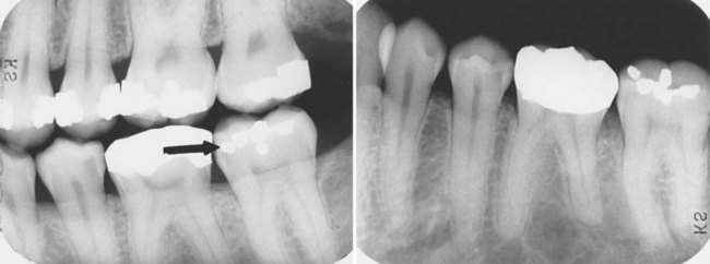
FIGURE 21-14 (Radiographs courtesy of Dr. Robert Jaynes, Assistant Professor, Oral Radiology Group, The Ohio State University College of Dentistry. From Haring JI, Lind LJ: Radiographic interpretation for the dental hygienist, Philadelphia, 1993, Saunders.)
12. In Figure 21-15, is the amalgam fragment between the maxillary second and third molars buccal or lingual? Why?
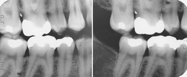
FIGURE 21-15 (Radiographs courtesy of Dr. Robert Jaynes, Assistant Professor, Oral Radiology Group, The Ohio State University College of Dentistry. From Haring JI, Lind LJ: Radiographic interpretation for the dental hygienist, Philadelphia, 1993, Saunders.)
13. In Figure 21-16, is the impacted canine located buccal or lingual to adjacent teeth? Why?
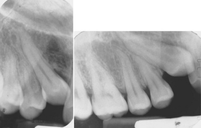
FIGURE 21-16 (Radiographs courtesy of Dr. Robert Jaynes, Assistant Professor, Oral Radiology Group, The Ohio State University College of Dentistry. From Haring JI, Lind LJ: Radiographic interpretation for the dental hygienist, Philadelphia, 1993, Saunders.)
14. In Figure 21-17, is the gutta percha in the labeled canal located on the buccal or lingual side of the tooth? Why?
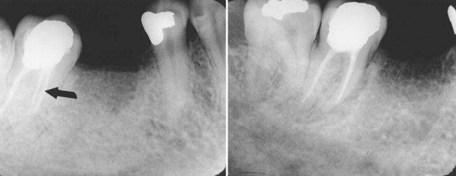
FIGURE 21-17 (Radiographs courtesy of Dr. Robert Jaynes, Assistant Professor, Oral Radiology Group, The Ohio State University College of Dentistry.)
15. In Figure 21-18, is the impacted canine located buccal or lingual to adjacent teeth? Why?
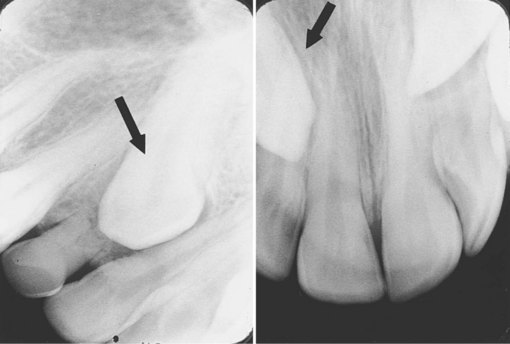
FIGURE 21-18 (Radiographs courtesy of Dr. Robert Jaynes, Assistant Professor, Oral Radiology Group, The Ohio State University College of Dentistry.)