BIOMECHANICS
The musculoskeletal system is essentially a mechanical system, designed to support, protect and move the body, and capable of adapting to changing mechanical demands (see Benjamin & Maganaris 2006, for a review of the ways in which different elements of the musculoskeletal system respond to exercise). Structures such as long bones and synovial joints have specific mechanical functions; the material properties of the skeletal tissues from which they are derived permit optimal adaptations to diverse mechanical demands.
The purpose of this section is to explain, in a non-mathematical way, how mechanical principles shape the human musculoskeletal system. Mechanical considerations explain why bones are stiff and tendons are tough, why the surfaces of some synovial joints are imperfectly matched, and why some tendons insert closer to joints than others. The emerging subject of ‘mechanobiology’ considers how cells adapt their matrix to prevailing mechanical demands and explains why some tissues are better at doing this than others.
MECHANICAL CONCEPTS
Forces, moments and torques
A force is an action which deforms an object, or which causes it to move, and can be termed compressive, tensile or shear, according to the manner in which it deforms objects (Fig. 5.52). A force F acting at the end of a lever of length L will generate a bending moment (F × L) acting about the pivot point of the lever. A torque or torsional moment (Fig. 5.52F) may be quantified in similar terms. The combined influence of several forces can be calculated as shown in Fig. 5.53. If the forces all act in the same direction, they may be added; if they act in different directions each force must be resolved into two imaginary components which act in two anatomically convenient directions at 90° to each other, using simple trigonometry. All components acting in the same direction are added to form two forces (S and C in Fig. 5.53) which can be used to calculate the magnitude and direction of the single resultant force (which has a similar effect to all of the individual forces combined). Forces acting on a stationary object are analysed according to the principle that all forces acting in any given direction must balance each other (i.e. add to zero) and all moments or torques acting about a given pivot point must also balance each other.
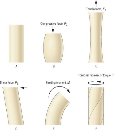
Fig. 5.52 The effects of different types of loading on a solid object (shown in A) are illustrated in B–F.
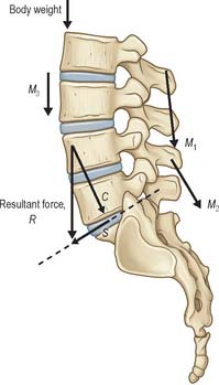
Fig. 5.53 The combined effect of several muscle forces (M1–M3) and body weight (W) can be calculated by resolving each force into two components acting in two anatomically-meaningful directions (in this case parallel and perpendicular to the mid-plane of the lumbosacral intervertebral disc). The components acting in these two directions are then summed to give the total compressive (C) and shear (S) forces acting on the disc. The magnitude and direction of the resultant force (R) which represent the combined effect of all four forces can be calculated using trigonometry.
Mechanical properties of structures
Most biological structures deform readily when a sufficient force is applied to them, but their resistance to deformation increases steadily as the magnitude of the force increases: the resulting graph of force against deformation resembles the one shown in Fig. 5.54. Stiffness is the ratio of force to deformation (typical units N/mm) and so is represented by the gradient of the graph. The initial region of low stiffness, or ‘toe region’, is followed by a stiffer region in which the graph is almost linear. In many biological structures, the ‘toe region’ can be explained by the straightening out of the zig-zag ‘crimp’ structure of collagen type I fibres, whereas the linear region represents direct stretching of the straightened collagen fibres. If the deformed structure springs back immediately to its original dimensions when the deforming force is removed, the deformation is termed elastic; a deformation that shows no sign of recovering is plastic, and one that recovers eventually, but gradually, is viscoelastic (see below). Strength is the force at which an object becomes damaged, and is usually interpreted either as the force at which the gradient of the graph first reduces (the elastic limit) or the force when the gradient falls to zero (the ultimate strength).
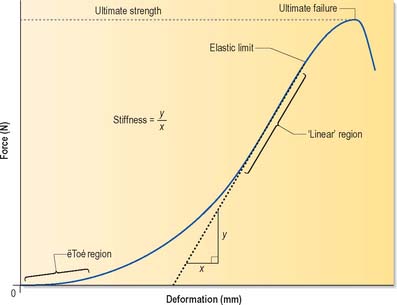
Fig. 5.54 A typical force-deformation graph for a skeletal structure subjected to mechanical loading. In the initial ‘toe region’, deformation increases rapidly with force, but this is followed by a linear region in which the deformation increases more slowly, and in proportion to the applied force. The gradient of the graph indicates the stiffness of the structure at any given load. Strength is the force at which an object becomes damaged, and this is usually interpreted either as the force at which the gradient first reduces (the elastic limit) or the force when the gradient falls to zero (the ultimate strength).
Properties of materials
The properties of materials must be expressed in such a way that they are independent of the size and shape of the structure they constitute. A force divided by the area over which that force is applied gives a stress value (force per unit area); the resulting deformation divided by the original length of the object gives a strain value (fractional or percentage deformation). Stress divided by strain is the size-independent material equivalent of the stiffness of an object, and is an important physical property termed the modulus. There are different types of modulus, but essentially they correspond to stiffness, or resistance to deformation.
Energy and shock absorption
Deforming an object may require a considerable expenditure of energy. Technically, the work done (or energy expended) is proportional to the average force exerted, multiplied by the distance moved. This is mathematically equivalent to the area under the graph in Fig. 5.55. For this reason, the area is referred to as the strain energy, i.e. the energy that has been expended in deforming the object. If the object has elastic properties, it will spring back to its original shape when the deforming force is removed, and all the strain energy is then released. (This release of energy explains why a stretched rope can recoil violently if it snaps.) Structures such as coiled springs, which can resist high forces and also deform extensively, are capable of storing large amounts of energy, and so can act as shock absorbers when they are continually compressed and stretched. Tendons act in a similar manner during locomotion: they store strain energy when their muscles contract, and release most of it as the muscles relax later in the gait cycle. A small fraction of the stored strain energy, the hysteresis energy, is dissipated as heat (Fig. 5.55), and can cause generation of heat in large tendons involved in vigorous repetitive activity. Any material or structure that is capable of absorbing large amounts of strain energy before failure is termed tough; otherwise it is brittle. From Fig. 5.55 it is apparent that tough materials must be both strong and extensible: examples of strong but brittle materials are glass and tooth enamel, which both undergo minimal deformation and so display very steep force-deformation graphs.
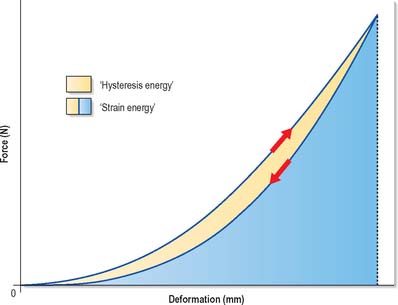
Fig. 5.55 This force–deformation graph shows how an object deforms when a force is applied to it (upwards arrow) and how it recovers its shape when the force is gradually released (downwards arrow). The area under the loading curve represents the strain energy that has been expended in deforming the object. The area under the unloading curve represents the energy that is given up when the object is allowed to spring back to its original shape. The small area in between represents energy which cannot be recovered but is dissipated as heat. This is the hysteresis energy.
Liquids
A liquid has negligible rigidity and so deforms readily to take the shape of its container. When compressed, it maintains practically the same volume, but it flows to equalize the intensity of loading within it. As a result, a static liquid under load exhibits a single internal pressure (force per unit area) that does not vary with location or direction. Even delicate objects are not deformed when immersed in a high pressure liquid if they themselves are filled with liquid, because the internal and external pressures on them are exactly equal, which explains why cells can survive high pressures in liquids without damage to their plasma membrane. Of the musculoskeletal tissues, only the nucleus pulposus of intervertebral discs exhibits true liquid behaviour, although other tissues such as bone and cartilage contain liquid which is able to move relative to the solid matrix that surrounds it.
Viscoelasticity
Materials are said to be viscoelastic if they behave partly like a thick (viscous) fluid and partly like an elastic solid. Viscoelastic deformations change with time, even when the deforming stress is constant, and complete recovery from such deformations also takes some time after the stress is removed (Fig. 5.56). In most biological materials, viscous behaviour occurs because applied loading causes fluid to flow from the most heavily loaded regions to the least loaded, by percolating through very small (nanometre-scale) pores in the matrix, a process which can take hours: for this reason, the term poroelastic is often preferred to viscoelastic when referring to tissues such as cartilage. Creep and stress relaxation are two important manifestations of viscoelasticity. Creep may be described as continuing deformation under constant load (Fig. 5.56), whereas stress relaxation is a gradual decrease in force resisted by a viscoelastic material when it is initially deformed by a certain amount, and then held with the same constant deformation.
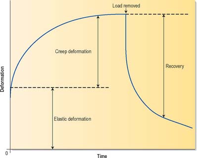
Fig. 5.56 The deformation of viscoelastic materials varies with time. In this example, a load is applied at zero time which causes an immediate elastic deformation, followed by a slowly increasing time-dependent deformation (creep). When the load is removed, some deformation is recovered immediately, but full recovery is achieved only slowly.
MATERIAL PROPERTIES OF SKELETAL TISSUES
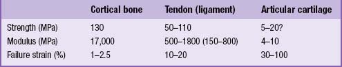
The material properties of several skeletal tissues are compared in Table 5.3.
Table 5.3 Tensile materials properties of skeletal tissues. For comparison, alloy steel has a strength of 600 MPa and a modulus of 20,000 MPa.
Bone
Bone consists mainly of collagen type I, and microcrystals of the mineral hydroxyapatite. Collagen gives bone considerable tensile strength, and renders it very tough when fractured, whereas the mineral component gives bone a very high compressive modulus and high compressive strength. Rigidity (stiffness) is the defining characteristic of bone: it enables the tissue to provide precisely shaped surfaces in synovial joints which will deform very little under load, and it also enables fast locomotion when muscles pull on bones. If bones were strong and tough but not rigid, rapid muscle contractions would cause them to bend alarmingly and would slow the angular movement of limbs.
Tendon, ligament and fascia
Tendons, ligaments and fascia consist primarily of densely packed collagen type I fibres, an arrangement that gives these structures very high tensile strength: the crimped structure of the collagen fibre bundles permits stretching by 10–15% before failure. This combination of strength and extensibility enables tendons, ligaments and fascia to absorb more strain energy per unit weight than any other biological material, and makes them very effective shock absorbers (Alexander, 1988). An important mechanical difference between tendons and ligaments is that ligaments often contain bundles of collagen fibres orientated in a range of directions, presumably because bones can be moved apart in a range of directions, whereas the fibres in a tendon are aligned only in the direction in which the muscle pulls on the tendon. Fascia usually contains collagen fibres aligned to resist forces in at least two different directions.
Hyaline cartilage
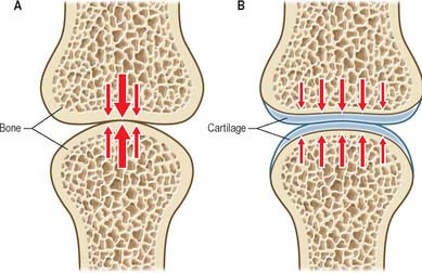
Hyaline cartilage consists mainly of very fine collagen type II fibrils and large proteoglycan molecules which have the property of attracting water and swelling. Collagen gives cartilage its tensile strength and stiffness, and the proteoglycans give the tissue a high water content that confers compressive ‘turgor’. During growth and healing, proteoglycans enable the growing cartilage to swell and occupy space that later will be strengthened by other components of the matrix. Articular cartilage is a particular type of hyaline cartilage that covers the ends of articulating bones: the high water content of the tissue enables it to distribute loading evenly on the underlying bone. Because cartilage is softer than bone, it exhibits a relatively greater degree of deformation when loaded. This increases the area of contact between articular surfaces and reduces the contact stress (Fig. 5.57). Sustained loading of a synovial joint for just a few minutes causes substantial cartilage creep, because water is expelled from the tissue. Creep causes the area of contact to increase, and further reduces the contact stress. Creep in articular cartilage also causes water to be exuded into the joint cavity, assisting in fluid film lubrication (see below). Articular cartilage ‘wear’ (measured in grammes) is the gradual loss of material from the surface in response to high and repetitive loading; it is minimized because the collagen type II fibrils in the superficial zone are aligned parallel to the surface, an arrangement that provides maximal resistance to surface splitting and the subsequent loss of tissue.
Fibrocartilage and elastic cartilage
Fibrocartilage and elastic cartilage combine the high proteoglycan and water content that characterizes cartilage with a high proportion of either thick collagen type I fibres (fibrocartilage) or elastin fibres (elastic cartilage). Collagen type I confers extra tensile strength and toughness, whereas elastin fibres provides elastic recoil, i.e. the ability to spring back to shape after large deformations.
MECHANICAL PROPERTIES OF SKELETAL STRUCTURES
Long bones
Long bones are characterized by enlarged ends covered in cartilage, a long hollow shaft, and various bony protuberances. The enlarged ends serve to reduce contact stress where long bones meet in synovial joints, and to increase the stability of such joints (Fig. 5.58). A different relationship between stability and mobility can exist in different anatomic planes, even for the same joint, e.g. the knee joint favours stability in the frontal plane, and mobility in the sagittal plane. The hollow shaft of a long bone confers high strength in bending, but also minimizes bone mass and so increases the speed of movement. Bending strength is increased by having as much bone mass as possible far from the axis of bending (Fig. 5.59). The precise cross-sectional shape of a long bone therefore gives a clear indication of the planes in which the shaft is most likely to be subjected to severe bending. Bony prominences or processes on long bones serve to increase the lever arm of muscles that are attached to them: if a large prominence is close to the centre of rotation of a joint, then the lever arm might increase by over 100%, and the maximum torque developed by the muscle about that centre of rotation would increase by the same amount.
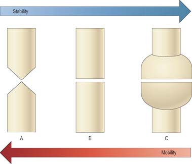
Fig. 5.58 In synovial joints, the shapes of the opposing bone ends largely determine how much movement is possible, and the stability of the joint. Tapered bone ends (A) lead to high mobility, but low stability (in the plane of the page). Conversely, very wide bone ends (C) lead to low mobility and high stability. Some joints resemble (A) in one plane, but (B) or (C) in others.
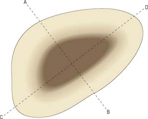
Fig. 5.59 Cross-section through the shaft of a long bone, showing how the irregular shape gives information about the bone’s strength in bending about different axes. Strength will be greatest about the axis A–B because a high proportion of bone mass is located a long distance from this axis, and so will resist bending very strongly. Strength will be minimal about the axis C–D for a similar reason.
Synovial joints
Typically, synovial joints are designed for full and free movements, but they must also provide some stability in specific planes (Fig. 5.58). In a joint with a small range of movement, intrinsic stability provided by the articular surfaces and ligaments of that joint may be more important than the extrinsic stability provided by surrounding muscles. Low friction movement is facilitated by the smooth surfaces of articular cartilage, made slippery by the presence of hydrophobic lubricants (surface-active phospholipids) which are bound to the cartilage surface. This boundary lubrication reduces friction during slow movements, especially when forces are high. During rapid movements, microscopic undulations in the cartilage surface trap small quantities of synovial fluid between the articular surfaces, so that fluid film lubrication (akin to aqua-planing) can also occur (Fig. 5.60), and friction and wear are greatly reduced. The sticky, viscous nature of synovial fluid enables it to persist between the cartilage surfaces for longer than water, which would be squeezed out much too quickly. Fluid film lubrication is assisted by joint incongruity, in which the opposing articular surfaces have slightly different curvatures (Fig. 5.61), producing a potential fluid filled gap which moves as the joint moves, washing synovial fluid across the cartilage surfaces. Incongruity can also help to reduce peak loading on the apex of the joint.
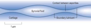
Fig. 5.60 The articular cartilage surfaces of synovial joints contain microscopic undulations which trap small quantities of synovial fluid between the surfaces. This enables fluid film lubrication to occur. Boundary lubrication at the points of contact between cartilage asperities is facilitated by lubricants adhering to the cartilage surface.
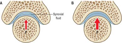
Fig. 5.61 Some synovial joints are incongruent in the sense that the opposing articular surfaces have slightly different curvatures. This ensures that there is a fluid-filled gap between them when the joint is subjected to low loading (A). Under high loading (B) this gap disappears, but peak loading at the apex of the joint remains lower than it would be if the surfaces had the same curvature, and this is a major advantage for an incongruent joint. The shape of the concave articular surface is sometimes referred to as a Gothic arch. F = Loading force.
Intervertebral discs
Intervertebral discs are composed of three tissues: the anulus fibrosus (fibrocartilage), the nucleus pulposus (a hydrated collagenproteoglycan gel), and the endplates (hyaline cartilage) (see Ch. 42). The water content of the nucleus pulposus can reach 90% in children and young adults, enabling the whole tissue to behave like a fluid. When compressive loading is applied to the vertebral column, the fluid pressure in the nucleus presses evenly on the adjacent vertebral bodies, even when they are orientated at small angles to each other. The anulus resists radial expansion of the nucleus, and can deform vertically to facilitate spinal bending in various planes. The relatively dense hyaline cartilage endplate helps to maintain a fluid pressure in the nucleus by slowing down water loss into the vertebral body through perforations in the vertebral endplate. Nevertheless, discs lose approximately 20% of their water gradually, in the course of the day. This nett loss of water is regained at night when, in recumbency, the load on the spine is relieved. Diurnal variations in disc water content cause adults to be approximately 2 cm taller in the early morning, and more flexible in the evening (see Ch. 42).
MUSCLES AND LEVER SYSTEMS
Collagenous architecture of muscle
Muscles are supported by a hierarchy of collagenous sheaths (endomysium, perimysium and epimysium) which surround individual muscle fibres, fascicles and whole muscles respectively. Muscles are bound together into functional groups by collagenous fascia. Together these sheaths create a strong honeycomb structure which contributes to the resistance of a muscle to tension. When muscle is stretched, high tensile forces in these collagenous structures contribute to the high forces which can be generated during eccentric (lengthening) muscle contractions.
Internal muscle forces
Generally speaking, muscle forces exert greater mechanical loading to the skeleton than does body weight. During relaxed standing, 50% of the compressive force acting on the lumbar spine arises from the antagonistic activity of the muscles of the back and abdomen, and 50% comes from superincumbent body weight. However, when bending the trunk to lift weights from the ground, more than 90% of the compressive force acting on the spine can be attributed to muscle tension (Fig. 5.62). Similarly, muscle forces acting on the knee can exceed body weight by a factor of 200–400% during stair climbing, and during deep squatting movements. Muscle forces can exceed the strength of adjacent bones if they contract in alarm, so that normal inhibitory reflexes are suppressed: it is not uncommon for vertebrae to be crushed by muscle tension during major epileptic fits. Muscle forces also rise to high levels when attempting to accelerate body parts. According to Newton’s 2nd Law of motion (force = mass × acceleration), it follows that any attempt to achieve maximum acceleration, e.g. during some sporting activity, will naturally require maximal muscle tension. The size and potential dangers of internal muscle forces are often overlooked, leading some authors to draw spurious distinctions between weight-bearing and non-weight-bearing joints, and suggesting erroneously that only the former are subjected to high loading: it is likely that a watch-maker’s finger joints are subjected to stresses as high, and as often, as those applied to his ankles.
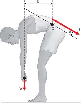
Fig. 5.62 During manual labour, muscle tension often rises to high levels in order to generate sufficient bending moment to move external objects. In this example, the back muscles act only a short distance (d) from the pivot point in the intervertebral discs, whereas the weight being lifted acts on a much bigger lever arm (D). In order for the moments to balance, the back muscle tension (F) must exceed the weight being lifted (W) by the ratio of D/d. In practice, this can lead to the lumbar spine being compressed by approximately 500 kg during moderate manual handling.
Muscle lever systems
Muscle tension generates bending moments and torques about joints. Moments and torques depend on lever arms as well as muscle forces. It is conventional (although not particularly instructive) to distinguish between three types of muscle lever system (Fig. 5.63). The length of the lever arm (the perpendicular distance between the muscle line of action and the centre of rotation of the joint) is more important than lever type (Fig. 5.64). If the lever arm is short, then a given muscle contraction will move the joint through a large angle, so the lever system is suited to large and/or rapid movements of that joint. Conversely, a long lever arm leads to small and/or slow movements, but greater moment generation. These considerations can reveal, for example, whether an animal’s jaws are designed to catch insects, or to crush nuts. Elite weight-lifters may have muscle insertions with particularly large lever arms about particular joints.
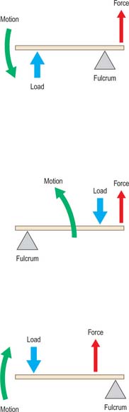
Fig. 5.63 Muscle lever systems can be classified as First class (A), Second class (B) or Third class (C) according to the relative positions of the pivot, the muscle insertion, and the externally-applied force.
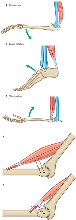
Fig. 5.64 The precise location of a muscle insertion relative to a joint greatly influences the function of that joint. A, If the perpendicular distance (d) between the muscle line of action and the centre of rotation of the joint (•) is large, then the joint is suited to slow but forceful movements. B, If d is small, then the joint is suited to rapid but less forceful movements.
MOVEMENTS
Movements of bones
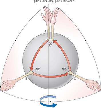
Movement of a bone is referred to as translation if it does not involve any change in orientation relative to a fixed frame of reference (or to another bone). A pure rotation involves no translation, merely a pivoting of the bone about some fixed point or centre of rotation. Spin is the rotation of a bone about its mechanical axis, which for a long bone would coincide with its long axis. Spin can occur in conjunction with other joint rotations (Fig. 5.65). Most body movements involve some combination of rotation, translation, and spin, although the translational component is often small.
Movements at articular surfaces
Opposing joint surfaces are never perfectly congruent. Nevertheless, substantial regions of opposing surfaces may fit together exactly in a certain position known as the close-packed position in which the joint is most stable, e.g. the close-packed position of the knee joint corresponds to full extension. In other (loose-packed) positions, the surfaces of incongruent joints are not perfectly matched, and are able to move relative to each other by a combination of spin, roll and slide (Fig. 5.66). In final close-packing, surfaces are fully congruent, in maximal contact and tightly compressed or ‘screwed-home’. The fibrous capsule and ligaments are maximally spiralized and tensed, and no further movement is possible. Close-packed surfaces cannot be separated by normal external force (as they may be in other positions), and bones can be regarded as temporarily locked, as if no joint existed. Close-packing is a final, limiting position, and any force which tends to further change can only be resisted by contraction of appropriate muscles. Failure to stop further movement results in injury to joint structures. Therefore movement just short of close-packing is physiologically most important.
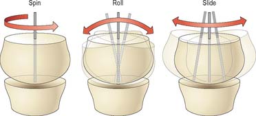
Fig. 5.66 The surfaces of incongruent joints move relative to each other by various combinations of spin, roll, and slide.
Ligaments and articular cartilage are to a small degree elastically deformable: in the final stages of close-packing the articular position is an equilibrium between the external moments and torques applied (often by gravity) and resistance to tissue deformation by the tense, twisted capsule and compressed cartilage surfaces. In symmetrical standing, the knee and hip joints approach close-packed positions sufficiently to maintain an erect posture with minimal energy. In all other positions the articular surfaces are not congruent and parts of the capsule are lax; the joint is said to be loose-packed. According to MacConaill & Basmajian (1977) the close- and loose-packed positions of joints are as shown in Table 5.4. Capsules are sufficiently lax near the mid-range of many movements to allow separation of the articulating surfaces by external forces. Opinions may vary in connection with some of the positions in Table 5.4, e.g. a close-packed position may possibly occur in occasional joints at both extremes of the range of movement. It is difficult to assess the situation in small tarsal and carpal joints and the first carpometacarpal joints. Intervertebral movements are the result of integrated simultaneous changes at all elements which make up the intervertebral articular complex, and perhaps should not be included in Table 5.4. However, most of the positions given do correspond with postures adopted when maximal stress is encountered.
Table 5.4 The close- and loose-packed positions of joints.
| Joint | Close-packed position | Loose-packed position |
|---|---|---|
| Shoulder | Abduction + lateral rotation | Semiabduction |
| Ulnohumeral | Extension | Semiflexion |
| Radiohumeral | Semiflexion + semipronation | Extension + supination |
| Wrist | Dorsiflexion | Semiflexion |
| 2nd–5th metacarpo-phalangeal | Full flexion | Semiflexion + ulnar deviation |
| Interphalangeal (fingers) | Extension | Semiflexion |
| 1st carpometacarpal | Full opposition | Neutral position of thumb |
| Hip | Extension + medial rotation | Semiflexion |
| Knee | Full extension | Semiflexion |
| Ankle | Dorsiflexion | Neutral position |
| Tarsal joints | Full supination | Semipronation |
| Metatarsophalangeal | Dorsiflexion | Neutral position |
| Interphalangeal (toes) | Dorsiflexion | Semiflexion |
| Intervertebral | Extension | Neutral position |
Data from MacConaill MA, Basmajian JV 1977 Muscles and Movements, 2nd edn. New York: Kriger.
Centre of rotation
The centre of rotation is a theoretical concept and may not correspond closely to any anatomical landmark. For a finite movement of one bone relative to a fixed reference (perhaps an anatomical plane), the centre of rotation can be located by (i) drawing theoretical lines between the initial and final positions of anatomical landmarks on the bone, and (ii) determining where the perpendicular bisectors of these lines meet (Fig. 5.67). Real movements of real joints often involve varying combinations of rotation and translation as the movement progresses. It can be instructive to break the whole movement down into a series of small movements, calculate the centre of rotation for each one, and then join up the centres to create the locus of the instantaneous centre of rotation for the whole movement. Joint disease sometimes leads to an abnormally long and tortuous locus of the centre of rotation, because degenerative changes can reduce the restraint to motion offered by one or more tissues.
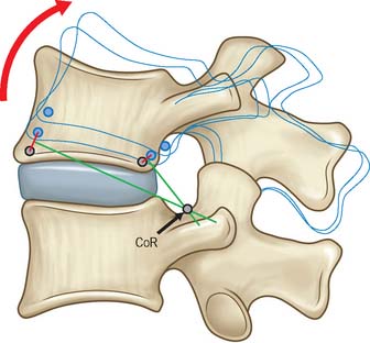
Fig. 5.67 When a bone is rotated, the centre of rotation (CoR) can be located by (i) drawing lines between the initial and final positions of anatomical landmarks on the bone, and (ii) determining where the perpendicular bisectors of these lines meet. The CoR may not correspond to a precise anatomical landmark.
Coupled movements
An attempt to move a joint in one plane sometimes causes articular surfaces to meet at an oblique angle, which can cause small rotations in other planes. These secondary rotations, which are usually smaller than the primary rotations, are referred to as coupled movements. As an example, lateral bending of the lumbar spine, which occurs in the coronal plane, also normally produces coupled axial rotations. Joint pathology can lead to abnormal coupled movements.
MECHANOBIOLOGY
Adaptive remodelling
Skeletal tissues are generally able to adapt their mechanical properties to match the forces applied to them. This process is best understood for bone, and bone biologists refer to this general principle as Wolff’s Law. As illustrated in Fig. 5.68, the degree of deformation of a tissue is proportional to the amount of mechanical loading to which it is subjected. Cells detect this increased strain and respond by producing more extracellular matrix, which increases the modulus (stiffness) of the tissue and returns strain levels to normal. Similarly, reduced loading leads to reduced tissue strain, reduced matrix synthesis, and reduced modulus, so that tissue strain increases to normal values. This negative feedback system ensures that bone adapts (remodels) to suit its mechanical environment. Animal experiments suggest that as few as 36 relatively severe loading cycles per day are sufficient to produce a maximal hypertrophic response in bone, whereas fewer than four loading cycles per day leads to tissue resorption. Evidently, bone cells respond to maximal loading rather than time-averaged loading. There is some experimental evidence that cartilage and tendon likewise adapt to their mechanical environment. It would be unlikely that they did not, because the mechanical properties of adjacent tissues would rapidly become mis-matched, increasing the risk of damage to one of them. However, it is equally evident that different tissues cannot adapt at the same rates. Highly vascularized tissues such as muscle and bone have the potential to adapt rapidly, whereas poorly vascularized tissues such as large tendons do not. Avascular tissues such as articular cartilage and intervertebral discs can adapt only very slowly, so that turnover times for some matrix macromolecules can be as long as 100 years. Large differences in adaptive potential between adjacent musculoskeletal tissues could lead to problems in the less well-vascularized tissue when levels of mechanical loading increase abruptly.
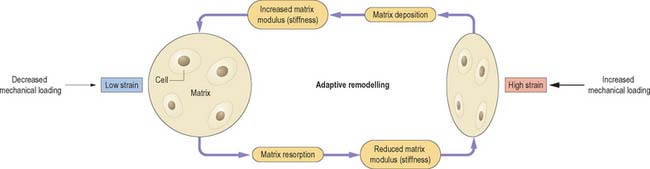
Fig. 5.68 Adaptive remodelling is the process by which musculoskeletal tissues adapt to prevailing mechanical demands. If a tissue is subjected to increased mechanical loading (right) it deforms more. Cells respond to this increased strain by depositing more matrix and increasing its modulus (stiffness) until strain levels return to normal. Similarly, reduced loading leads to reduced tissue strain (left), reduced modulus, and reduced matrix deposition until strain levels rise to normal.
Mechanotransduction
Various mechanisms have been proposed to explain how cells in musculoskeletal tissues detect mechanical loading. Cells in bone appear to respond to tissue strain, possibly by detecting fluid flow within the microscopic canaliculi of the matrix (reviewed in Klein-Nulend et al 2003). Cells in cartilage and ligaments also appear able to detect tissue strain, possibly because fluid flow in the surrounding matrix deforms the cells in shear (Fig. 5.52). Cells in articular cartilage and in the nucleus pulposus of intervertebral discs can detect hydrostatic pressure in the surrounding medium, although only the cells in the nucleus would normally experience such a pressure in life. Muscle cells respond to strain and microinjury. Mechanotransduction appears to be mediated by matrix molecules such as fibronectin, by transmembrane proteins such as integrins, and by a range of intracellular proteins such as titin in muscle.
Degeneration, injury and frustrated repair
Numerous theories have been propounded to explain degenerative changes in skeletal tissues. Most presume that the cells behave abnormally, possibly because of an unfavourable genetic inheritance, so that the matrix becomes weakened and physically disrupted. Alternatively, degenerative changes may represent an attempt by the cells to repair a matrix where the primary cause of damage has been excessive mechanical loading. In poorly vascularized tissues, such as cartilage and tendon, low cell density and inadequate transportation of metabolites could lead to a vicious circle of minor injury, frustrated repair, tissue weakening, and further injury.