9 Contemporary fixed appliances
Most orthodontic treatment is carried out using fixed appliances, directly attached to the teeth. Development of these appliance systems began in the USA at the turn of the twentieth century and they have become progressively more sophisticated. Fixed orthodontic appliances are required for accurate tooth positioning. The brackets, archwires and auxiliary components that make up a fixed appliance are responsible for mediating tooth movement and this takes place at the tooth–bracket interface.
The evolution of fixed appliances
The predominant fixed appliance system in use today is based around a bracket with a rectangular edgewise slot and an in-built prescription for each individual tooth position. A number of modifications on this basic design now exist, largely concerned with the method of attaching the archwire within the bracket slot and either positioning the bracket on the labial or lingual surface of the tooth. However, another group of fixed appliance light wire systems have also been developed, which allow much greater amounts of tooth tipping during the early stages of treatment.
The standard edgewise appliance
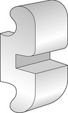
The standard edgewise appliance originated from the work of Edward Angle, who experimented with a series of systems before developing the edgewise slot, on which most fixed appliances are now based (Angle, 1928). Initially placing the slot vertically, Angle found that by laying it horizontally within the bracket, greater control of the teeth could be obtained (Fig. 9.1): the interaction of a rectangular wire in a rectangular slot providing precise three-dimensional control of tooth position. The standard edgewise appliance became the fixed appliance of choice up until the late 1970s (Fig. 9.2), but it did suffer from several disadvantages. In particular, the passive bracket slot meant that final detailing of tooth position in rectangular wires was dependent upon many bends being placed within the archwire for each individual tooth (Fig. 9.3). This was time-consuming and required considerable skill on the part of the orthodontist. The presence of these bends also meant that space closure had to be carried out with closing loops, which were also complicated to bend (see Fig. 9.2). In addition, teeth are moved bodily along the archwire through alveolar bone using an edgewise appliance, which is demanding upon anchorage.
Light wire appliances
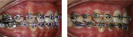
In an effort to overcome the high anchorage demand associated with the standard edgewise appliance, an Australian orthodontist, P. Raymond Begg developed a fixed appliance system where tooth movement was based around the concept of differential force (Fig. 9.4) (Begg, 1956):
Figure 9.4 Begg treatment involves the concept of differential force.
The tooth crowns are first tipped into the desired position and then the roots are uprighted. This differential tooth movement requires less anchorage than bodily moving teeth.
It is much easier to tip a tooth than move it bodily and this requires less force, so the Begg technique was much lighter on anchorage and became very popular during the 1960s and 1970s (Fig. 9.5). Begg treatment mechanics are compartmentalized into three stages, each with specific objectives that have to be achieved before progressing (Cadman, 1975a, b) (Box 9.1). However, because it only uses round archwires, precise finishing is difficult and the use of auxiliaries in the final stages of treatment to upright teeth that often have been tipped through quite significant distances proved to be quite complex, difficult to control and also time-consuming. In an effort to address this, the Tip-Edge appliance was developed by Peter Kesling in the late 1980s (Kesling, 1988; Kesling et al, 1991). This appliance also tips the teeth during the initial phase of treatment, but allows later uprighting with more rigid three-dimensional control by closing the slot down around full-size rectangular archwires (Fig. 9.5).
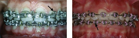
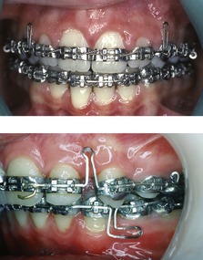
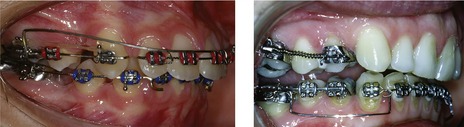
Fig. 9.5 A fully banded Begg appliance (left) and bonded Tip-Edge® appliance (right).
Both these appliances use auxiliary springs (arrowed) to upright the teeth during the final stage of treatment.
Box 9.1 Stages of Begg treatment
The Begg technique is divided into three separate and distinct stages of treatment, each with specific goals that should all be achieved before moving into the next stage. For all of these stages there is an emphasis upon overcorrection of tooth position.
The preadjusted edgewise appliance
After studying a large sample of untreated ideal occlusions, Lawrence Andrews published his six keys of occlusion (see Box 1.2) (Andrews, 1972) and introduced an edgewise bracket system that has revolutionized fixed appliance orthodontics (Andrews, 1979). The preadjusted edgewise or ‘straight-wire’ appliance that Andrews described is the most popular fixed appliance system in use today (Fig. 9.6). Unlike standard edgewise brackets, which are identical for each tooth and require bends within the archwire to generate individuality of tooth position, each tooth in the preadjusted edgewise system has a customized bracket. This built-in prescription was based around Andrews’ measurements from the untreated sample of ideal occlusions he studied and included a number of features (Fig. 9.7):
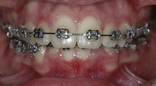
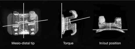
Figure 9.7 Pre-adjusted Siamese edgewise brackets showing twin design and contoured base.
The bracket prescription will position the tooth in three dimensions, generating mesiodistal tip, torque and in/out positioning.
In this preadjusted system, the work in accurately positioning the teeth is done by the bracket prescription, significantly reducing the amount of wire bending required. A further advantage is that it also allows groups of teeth to be moved and spaces closed by sliding them in unison along a rigid archwire; because once tooth alignment has been achieved, the archwire sits passively in each bracket slot.
The original Andrews bracket prescription is still available, although there have been adaptations made as the appliance system has been developed clinically (Box 9.2). In particular, it was found that some of the torque prescriptions in the original Andrews appliance were not being fully expressed, most notably in the upper incisors due to the ‘slop’ or free space that inevitably exists between the wire and bracket slot. Therefore, many later prescriptions have increased torque values in the upper labial segment to compensate for this. Biological and anatomical variation, as well as mechanical deficiencies associated with the appliance, mean that one overall prescription does not fit all cases. A variety of modifications in bracket prescription and occasionally some wire bending are often required during the normal clinical use of a preadjusted appliance. These may be needed to overcome errors in bracket positioning, significant variations in tooth structure or position, and the presence of marked skeletal discrepancies (Creekmore & Kunik, 1993; Thickett et al, 2007).
Lawrence Andrews described the original bracket prescriptions for his preadjusted appliance based upon data he obtained measuring tooth positions from untreated ideal occlusions (Andrews, 1972). As experience was obtained with this appliance during clinical use, Andrews went on to describe several different bracket series for extraction and non-extraction cases, in addition to series for use with different amounts of crowding. The extraction series brackets included adjustments for tip and rotation to counter the effects of space closure (Andrews, 1976), but overall these different series significantly complicated stock management for the orthodontist.
In contrast, Ronald Roth recommended a single series based on the Andrews extraction prescription. This prescription had extra torque in the upper labial segment because the edgewise slot does not express the full torque value of the bracket, particularly as the upper labial segment is retracted during space closure. Roth also placed a greater emphasis on functional occlusion and gave the canines greater tip to facilitate cuspal guidance. There was also greater torque in the maxillary molar region to prevent dropping of the palatal cusps and eliminate non-working side interferences (Roth, 1976).
More recently, Richard McLaughlin, John Bennett and Hugo Trevisi have developed the MBT prescription, which has increased torque in the upper labial segment and lingual crown torque in the lower labial segment. This was designed to minimize proclination of the lower incisors during treatment. The MBT prescription also has reduced tip, most notably in the upper arch, to reduce anchorage requirements. In addition, reduced torque in the lower molar region helps to prevent lingual rolling of lower molars as they are moved along the archwire (McLaughlin & Bennett, 1990).
Lingual appliances
One of the biggest problems associated with labial fixed appliance systems are the poor aesthetics. To overcome this, lingual appliance systems were introduced in the USA in the 1970s (Alexander et al, 1982). However, these proved to be clinically very difficult to use and with the introduction of aesthetic labial brackets, lingual orthodontics virtually disappeared from clinical practice in the USA. However, in Europe and Asia, several systems have been developed more recently and the technique is growing in popularity (Fig. 9.8) (Wiechmann, 2002). The principle advantages of lingual appliances are the improved aesthetics, lack of labial decalcification in cases with poor diet or plaque control and better bite opening due to a bite plane effect of the brackets. Disadvantages for the patient include problems with speech, soreness of the tongue and increased cost; whilst for the orthodontist, there is the inherent difficulty and time required for chairside adjustment.
Components of fixed appliances
Fixed orthodontic appliances consist of three main components:
Brackets
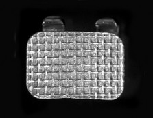
Orthodontic brackets are fixed to the tooth crown and mediate forces applied by the archwire and auxiliaries on the tooth. Brackets are either routinely cast or injection-molded from stainless steel; although to reduce the chance of allergic reaction, nickel-free brackets made from titanium or cobalt chromium are now available. Bonding techniques rely on a physical interaction being established between the bracket base and an etched enamel tooth surface. Bracket bases are therefore roughened or sandblasted to improve this bond (Fig. 9.9) and often curved in both the horizontal and vertical planes, which aids in bracket location and seating on the tooth crown (see Fig. 9.7).
Edgewise brackets
Edgewise brackets have rectangular slots, which are deeper in the horizontal as opposed to vertical plane. Slot and archwire dimensions have traditionally been described empirically, with the original dimensions being 0.022 inches vertically and 0.028 inches horizontally to accommodate gold archwires, which were quite soft. Once stiffer stainless steel archwires were introduced, slot size was reduced to 0.018 inches vertically and 0.025 inches horizontally. However, with greater uptake of preadjusted edgewise systems, there has been a move back to the original slot dimension. This allows increased dimensions of the working archwire and provides better overbite and torque control during space closure with sliding mechanics. Edgewise brackets are fabricated with a single archwire channel and two tie-wings (see Fig. 9.1); or more commonly as Siamese or twin brackets, which have four tie-wings (see Fig. 9.7). Siamese designs have an increased bracket width, which produces better control of tooth rotations and root position; whilst the presence of two separate tie-wings allows partial ligation of crowded teeth during initial alignment. However, the increased width of Siamese brackets results in a reduced interbracket span and some compromise in flexibility of the archwire during early alignment.
Aesthetic edgewise brackets
A significant disadvantage of metallic orthodontic brackets is their poor aesthetics; edgewise bracket systems that are transparent, or more closely resemble natural tooth colour, have therefore been developed (Fig. 9.10). The early aesthetic brackets were made of acrylic and polycarbonate, which discolored quite rapidly and were prone to both permanent deformation and failure. To overcome these problems, plastic brackets were made in polyurethane or polycarbonate reinforced with ceramic or fiberglass fillers.
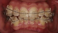
Figure 9.10 Ceramic preadjusted edgewise bracket.
Note the excessive composite ‘flash’ around a number of these brackets. This should be removed to prevent plaque accumulation in these areas.
Ceramic brackets were introduced in the 1980s and provide higher strength, more resistance to wear and deformation, better colour stability and superior aesthetics. They are manufactured from aluminium oxide and are described as either mono- or polycrystalline, depending upon whether they are made from one or many crystals. Although the aesthetics are significantly improved, they are not without disadvantages compared to metal brackets (Russell, 2005). Ceramic brackets have low fracture toughness, which can lead to higher bracket breakage. There is also greater friction between the archwire and bracket slot, which can be reduced by the incorporation of a metal slot. Excessively high bond strengths, particularly in the earlier brackets, also increased the risk of enamel damage on bracket removal. One final problem is the fact that ceramics are harder than enamel. This can result in significant enamel wear if brackets are placed in a position of occlusal contact with the natural dentition, commonly the lower incisors in cases with an increased overbite. Despite these problems, adult patients often request ceramic brackets because of the improved aesthetics.
Light wire appliance brackets
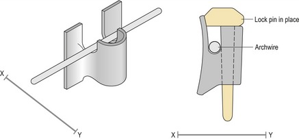
The original light wire appliance was the Begg appliance, which utilized a simple bracket that was identical for each tooth. Begg brackets incorporate a narrow open-ended slot, into which a stiff round archwire is placed from the gingival aspect and held in position by the insertion of a small metallic auxiliary lock pin (Fig. 9.11). The loosely fitting round wire allows considerable scope for the teeth to tip under the influence of light intermaxillary elastic traction, which in combination with anchor bends placed in rigid archwires, allows rapid reduction of both overbite and overjet during initial treatment. Following this, a variety of auxiliary springs are required to upright and torque the teeth into the correct position. Unfortunately, this stage of treatment is quite complicated and the nature of the bracket slot means that precise control of tooth position is difficult. For these reasons, the Begg appliance has diminished in popularity during recent years.
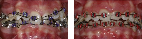
The Tip-Edge bracket has been modified from an edgewise design to facilitate the advantages of free tooth-tipping on round wires during early treatment, followed by accurate tooth positioning on rectangular wires during the later stages. This has been achieved by designing a narrow preadjusted edgewise bracket with wedges removed from each side of the archwire slot, which allow the bracket to tip up to 25° either mesially or distally. Lateral extensions or wings on the bracket provide good rotational control of tooth position and as the bracket tips, the dimensions of the slot increase. This allows the subsequent placement of rectangular wires; as the teeth are then uprighted with auxiliary side-winder springs, the slot dimension closes down and the prescribed tip and torque within the bracket is expressed (Fig. 9.12) (Parkhouse, 1998). More recently, the Tip-Edge PLUS bracket has been introduced, which eliminates the need for auxiliary springs by incorporating a tunnel deep to the main bracket slot (Fig. 9.13). A superelastic auxiliary archwire placed into this tunnel during the final stages of treatment provides the uprighting forces necessary for the bracket prescription to be expressed (Parkhouse, 2007).
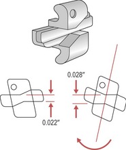
Figure 9.12 Tip-Edge® bracket.
As the tooth tips, the bracket slot dimension increases from 0.022 inches to 0.028. Uprighting on rectangular wires under the force of an auxiliary spring during the final stages of treatment closes down the slot and allows the bracket prescription to be expressed in three dimensions.
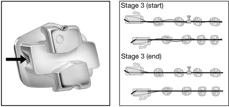
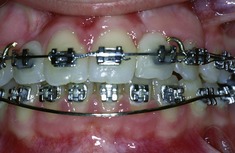
Figure 9.13 Tip-Edge PLUS® bracket with auxiliary tunnel (arrowed) deep to the main bracket slot.
A flexible nickel titanium archwire passes through the auxiliary tunnels and collectively does the work of individual side-winders. This allows simultaneous torque and tip delivery to be maintained as the teeth upright. During the final stage (three) of treatment, a passive rectangular archwire maintains arch shape and ensures correct torque delivery as a flexible superelastic archwire running through the auxiliary tunnels acts to provide the necessary uprighting tip. This tip brings the finishing surfaces of the main archwire slots into full contact with the rectangular main archwire and therefore, both tip and torque are corrected.
Reproduced with permission from Parkhouse (2008) Tip-Edge Orthodontics (St Louis: Mosby Elsevier); and with thanks to Richard Parkhouse. ®TP orthodontics, Inc. – La Porte, Ind. USA.
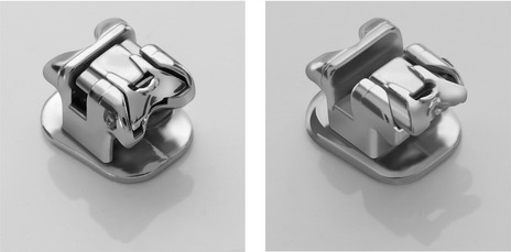
Self-ligating brackets
Friction between the bracket and the archwire can theoretically result in a loss of anchorage and slower tooth movement. In addition, individual bracket ligation with conventional edgewise appliances is time-consuming for both patient and orthodontist. In an attempt to reduce friction and appointment times, a range of brackets whose slot is closed by the use of a metal gate or clip are now available (Fig. 9.14). This technique is referred to as self-ligation, as the ligation system is built into the bracket. The concept is not new, having been originally pioneered in the 1930s. However, these bracket systems have undergone a renaissance over the past two decades, largely because of enhanced ingenuity and reliability. Self-ligating brackets provide a number of theoretical advantages over conventional appliances (Harradine, 2003):
Archwires
The original archwires used in orthodontics were made of gold but metallurgical advances have meant that a wide range of metal alloys are now available. These different alloys all offer a variety of physical properties, which can be defined (Box 9.3). The ideal properties required of an orthodontic archwire will depend upon the stage of treatment and the type of tooth movements being carried out and no archwire material will offer all of these together (Kapila & Sachdeva, 1989). For this reason, a number of different archwires are required during a course of orthodontic treatment and these will vary in both the type of metal used and the dimensions. The particular sequence that an orthodontist chooses is often down to personal preference.
Box 9.3 Physical properties of an archwire
The physical properties of an archwire material can be described in relation to a plot of stress (force per unit area) versus strain (deflection per unit length) as it is loaded under tension (see Figure).
A number of other features of an archwire should be considered, although they cannot be identified on a stress–strain graph.
Tooth alignment during the initial stages of treatment requires the following properties:
For this reason, round nickel titanium, stainless steel multistrand or coaxial wires are generally used and these will progress in diameter from 0.012 to 0.018 inches, depending upon the degree of irregularity associated with the dentition. These are often followed by a short period with a rectangular nickel titanium archwire to begin torque expression.
Once initial alignment has been achieved, wires of increasing stiffness are used to complete the process of levelling the dentition, begin overbite reduction and allow sliding of teeth along the archwire. These are usually round stainless steel wires, which provide the necessary stiffness over a range of diameters from 0.016 to 0.020 inches.
During the later stages of treatment, the process of overbite reduction is completed and if necessary, space closure is carried out by moving blocks or individual teeth, either along the archwire with sliding mechanics under force provided by auxiliaries or with the archwire under force provided by closing loops. In both circumstances, the archwire will require the following properties:
For sliding mechanics, the frictional properties of the archwire will also have a significant influence on the efficiency of tooth movement, whilst for space closure with looped archwires, good formability will be important. Archwires used during the later stages of overbite reduction and for space closure tend to be made of rectangular stainless steel.
Archwire materials
The metal alloys currently used for the fabrication of orthodontic archwires include stainless steel, nickel titanium, cobalt chromium and beta titanium.
Stainless steel
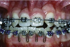
Stainless steel is an alloy consisting of iron, chromium and nickel, which has a large modulus of elasticity. As such, stainless steel archwires are generally stiff and resist deformation, which makes them ideal as working archwires, providing support as teeth are moved along the wire. However, this stiffness makes them poor for initial alignment; it is difficult to tie a stainless steel archwire into a crowded dentition and if this is achieved, it is often accompanied by permanent deformation. Stainless steel wires used in orthodontics consist of iron (70%), chromium (17 to 20%), nickel (8 to 12%) and a maximum of 0.08% carbon. These are known as ‘18-8’ stainless steels, reflecting the amount of chromium and nickel in the alloy. Chromium makes the wire resistant to corrosion in the oral environment, whilst nickel increases ductility. Stainless steel can be softened by annealing, hardened by cold-working during manufacture and springback can be improved by increasing the length of wire between brackets, achieved by incorporating loops (Fig. 9.15). Alternatively, the flexibility of stainless steel archwires can be increased by winding several smaller wires together to form large multistrand or twistflex wires; or wrapping smaller wires around a larger central wire to produce a coaxial wire. This is because the force delivered by a wire is related to the radius of the individual wires that make up an archwire.
Cobalt chromium
Commercially marketed as Elgiloy, cobalt chromium has a greater formability than stainless steel and similar stiffness, but with greater friction. It can be hardened by heat-treating in the laboratory and is used for the construction of auxiliaries, such as an intrusion arch or quadhelix.
Beta titanium
Introduced in the 1980s, beta titanium wires have good formability, with a stiffness of around one-third that of stainless steel; but they are also associated with higher friction. These archwires are used in the final stages of treatment, when finishing bends may be required to detail individual tooth position and achieve settling of the occlusion.
Nickel titanium
Nickel titanium or ‘NiTi’ archwires are characterized by high flexibility and the delivery of low force over long range. They also exhibit the phenomenon of shape memory; when deformed they will tend to return to their original shape; and superelasticity, the wire delivering the same force over a large range of deformation (Fig. 9.16). This behaviour occurs because nickel titanium undergoes a phase transition of crystalline structure on loading and unloading. These two phases are represented by the low stiffness martensitic crystal structure and the higher stiffness austenitic, with the superelasticity of NiTi archwires correlated to the coexistence of these two phases. It is also important to note that the deactivation plateau is lower than the activation, a phenomenon called hysteresis, which means that the force delivered by the wire to the tooth is lower than that needed to activate it.
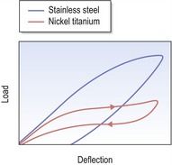
Figure 9.16 Plot of stress versus strain for a nickel titanium wire compared to stainless steel.
The plateau on the nickel titanium graph represents a phase shift in the crystalline structure of the metal on loading and unloading. The result is that the wire will deliver the same force over a large range of deformation, a property known as superelasticity. In addition, the deactivation plateau is lower than that for activation; less force is delivered on unloading than is required to activate the wire, a property known as hysteresis.
Nickel titanium was originally developed by the Naval Ordinance Laboratory in the USA in the early 1960s as nitinol and was introduced into orthodontics a decade later. The early wires had their crystalline structure stabilized or fixed in the martensitic form by cold working and exhibited greater flexibility but no shape memory. Later nickel titanium wires exhibited a phase shift in crystalline structure, induced by either mechanical stress such as ligation into a displaced tooth (pseudoelastic) or temperature change on placement into the oral cavity (thermoelastic). In combination, these properties give the wire its shape memory. The transitional temperature can be altered by changing the composition of the alloy, in particular by partially replacing the nickel with copper. In modern wires it is set at around body temperature. The wire outside the mouth is in the martensitic form and very flexible, allowing easy engagement into displaced teeth. As the wire reaches body temperature on placement in the mouth, the reverse occurs and it transforms into the austenitic form, returning to its original shape and imparting a gentle aligning force on the teeth. This force remains light because the pseudoelastic property of the wire ensures that when it is engaged in the bracket slot of a displaced tooth, the deflection of the wire (if it is sufficient enough) will generate a local martensitic transformation. As it unloads in these areas, the force will be lowered as the wire becomes superelastic, as exhibited by the plateau of the force–deflection graph (Fig. 9.16). Once the tooth is aligned, the reduction in wire deflection will restore the stiffer austenitic phase.
These wires are ideal for aligning teeth during the initial stages of treatment. However, the properties of low stiffness and poor formability make nickel titanium an unsuitable material for later stages of treatment where a stiffer archwire is required for space closure and overbite control.
Auxiliaries
A variety of auxiliary components are also required for the successful use of fixed appliances. These include both elastomeric and metallic products (Fig. 9.17).
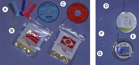
Figure 9.17 Elastomeric and metallic auxiliaries used with fixed appliances.
Elastomerics include (A) ormolasts or modules; (B) elastics; (C) powerchain. Metallic auxiliaries include (D) long ligatures; (E) open and closed coil; (F) short ligatures; (G) Kobyashi ligatures.
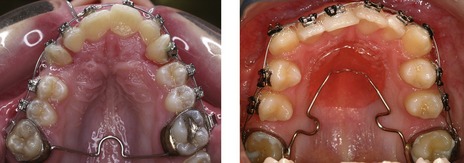
Palatal and lingual arches
Palatal and lingual arches consist of a rigid stainless steel wire soldered onto molar bands. The orthodontist fits the relevant molar bands in the mouth but does not cement them in place. An impression is taken with the bands in situ and they are transferred with the impression, to be cast up on the working model by the technician who then constructs the relevant arch. The appliance is then cemented into place within the mouth.
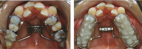
Fixed expansion arches
Fixed expansion arches are also fabricated in the laboratory and require a cast model of the maxillary arch incorporating orthodontic bands for their construction in a manner similar to that of palatal and lingual arches.
Placement and manipulation of fixed appliances
Prior to the development of direct bonding in the 1980s, the only way to place a fixed appliance was by spot-welding the brackets to stainless steel bands and individually banding all the teeth, including the incisors (see Figs 9.2 and 9.5). In current practice, it is possible to bond all the teeth, but molars are still commonly banded.
Molar banding
Molars are generally banded because their restricted access can make moisture control and accurate positioning for bonding more difficult. In addition, the increased forces of mastication associated with the molar dentition can lead to increased bond failures in these regions. A number of specific indications exist for banding instead of bonding molar teeth:
To create space for the placement of bands, the contact points need to be opened by placing separators between the teeth for a few days (Fig. 9.22). The most common separators are small elastomeric rings; however, if a contact point is particularly tight, or a restoration is in the way, metal separators can also be used. The separators are removed immediately prior to band placement and the opened contact point facilitates easy band placement around the tooth. Orthodontic bands are seamless and come preformed in various sizes. The appropriate size is selected and the band fitted by finger pressure and then occlusal force as the patient is asked to bite down on a bite-stick, which seats the band in the correct position. Once the correct band has been selected and tried in, it is removed and then cemented in place. Glass ionomer cement is recommended, as it chemically bonds to enamel and releases fluoride, which helps prevent demineralization.
Bracket placement
Both standard edgewise and Begg brackets are simply placed at a specific distance from the occlusal edge of the tooth crown. However, this does not provide a consistent reference point, as the bracket position is determined primarily by the size of the crown. With contemporary preadjusted appliances, the aim is to place the bracket at the centre of the anatomical crown and parallel to the long axis of the tooth. This means that the bracket prescription will be expressed correctly in relation to mesiodistal tip, torque and in/out position, irrespective of the size and form of the tooth. Bracket positioning can be achieved in two ways:
Orthodontic brackets are generally bonded to enamel using mechanical locking created by acid-etching the enamel surface of the teeth. The steps involved in bonding are as follows (Fig. 9.23):
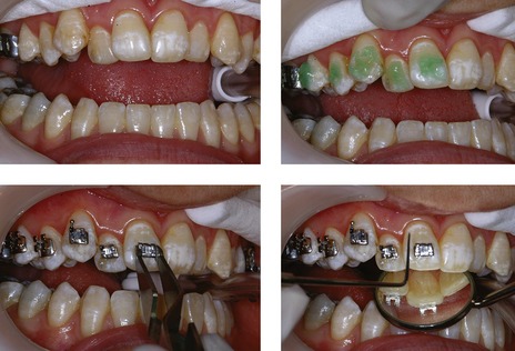
Moisture control is obtained, acid etch placed, the tooth surface washed and dried, and brackets positioned. Excess composite flash is removed and the composite either cures chemically or via the application of an external light source.
It is very important to clean up excess composite or ‘flash’ (see Fig. 9.10) as this can create problems in maintaining high levels of oral hygiene and result in demineralization around the bracket, a major risk of fixed appliance therapy.
Wire placement
In conventional fixed appliances the orthodontic archwires are held in place with ligatures that pass over the archwire and under the bracket tie-wings. These ligatures can be elastomeric or steel, the latter providing securer ligation and reduced friction, but taking longer to place. Self-ligating bracket systems use a variety of methods to mechanically lock the archwire into the bracket slot.
Removal of appliances
Bands are removed using special pliers, which exert an occlusally directed force from the gingival margin (Fig. 9.24). Because of the anatomy of molar teeth, the force is applied from the palatal aspect in the maxillary arch and buccally in the mandible.
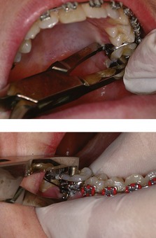
In contrast to bands, the bond strength for bondable attachments must be higher to prevent repeated failures. The aim upon removal of a bonded fixed appliance is for the failure to occur between the bracket base and composite junction, and not at the junction between enamel and composite, to avoid the risk of enamel fracture. To achieve this, a shear force is applied across the bracket base with debonding pliers (Fig. 9.25). This distorts the bracket base and causes failure at the junction between bracket base and composite. Residual composite is removed from the tooth, ideally using a tungsten carbide fissure burr in a slow handpiece.
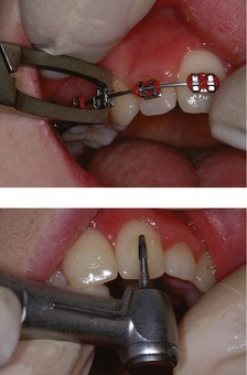
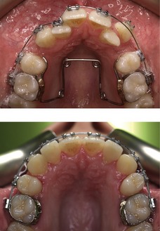
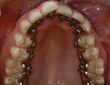
Figure 9.26 Tooth alignment and levelling in the maxillary arch (note the use of a quadhelix to expand the arch).
Ceramic brackets initially had very high bond strengths, which resulted in a significant risk of enamel fracture on debonding. To overcome this, most contemporary systems have a failure point built into the bracket base, which means that when a shear force is applied, the bracket fractures down the midline, collapsing the tie-wings of the bracket that can then be easily removed.
Stages of fixed appliance treatment
Treatment with fixed orthodontic appliances can be separated into a number of phases, each with a list of specific objectives.
Levelling and aligning
The first phase in all fixed appliance treatment is to align and level the dentition. Levelling means the correction of marginal ridge discrepancies as opposed to definitive overbite control. To achieve this, small-diameter flexible nickel titanium or multistranded steel arch wires are used (Figs 9.26 and 9.27).
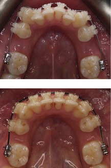
The aligning archwires are initially ligated into all the brackets, either fully or partially, unless a tooth is severely crowded and short of space. In this case, space will need to be created before the tooth can be aligned. This can be achieved by aligning the other teeth first and then placing a more rigid wire, such as stainless steel. A length of compressed coil spring placed on this archwire is then used to create space for the crowded tooth (Fig. 9.28). Once space has been created, the tooth can be aligned by placing a lighter, more flexible archwire as described earlier.
The alignment stage of treatment is completed when the working archwire is fully engaged in all the brackets. The working archwire when using a 0.022 × 0.028 inch bracket slot is usually a 0.019 × 0.025 inch stainless steel archwire. This provides sufficient rigidity for overbite reduction and control, and for space closure using sliding mechanics.
Overbite control
A number of techniques for facilitating overbite reduction are available and these vary between appliance systems. The Begg and Tip-Edge techniques are characterized by an initial stage of treatment concerned with tooth alignment that takes place simultaneously with both overbite and overjet reduction. This is achieved by using a combination of rigid steel archwires that bypass the premolar teeth and light intermaxillary elastic traction to tip the labial teeth. The steel wires have tip-back anchorage bends to create an intrusive force on the labial dentition, whilst the intermaxillary elastics have an extrusive effect on the molars. In combination, these mechanics are very effective in helping to reduce a deep overbite (Fig. 9.29).
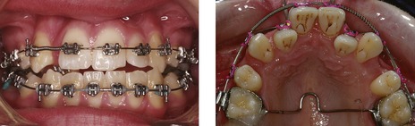
Edgewise and preadjusted edgewise appliances begin the process of overbite reduction following initial tooth alignment and use continuous rigid archwires, often with a reverse curve of Spee in the lower archwire (Fig. 9.30 and see Fig. 11.15). The working archwire is usually rectangular and composed of stainless steel. Care needs to be taken to prevent lower incisor proclination with these archwires and lingual crown torque is usually placed in the labial segment of the wire to prevent this. Much like the Begg and Tip-Edge appliances, the use of class II intermaxillary elastics can also aid in bite opening, as the vertical component of force will produce molar extrusion.
Edgewise appliances can also use utility arches and segmental mechanics to aid overbite reduction. Utility arches are auxiliary archwires that bypass the buccal segments and provide an intrusive force direct to the labial dentition. These arches are stabilized for anchorage posteriorly and act directly to intrude the incisors, being tied directly into the incisor bracket slots (Ricketts utility arch) or above an archwire that has been sectioned distally to the lateral incisors (Burstone intrusion arch). Utility arches are mechanically efficient, but do create a step in the archwire; they are also complex to fabricate and require triple tubes attached to the molar bands. However, they can be a useful adjunct in cases with deep bites (Fig. 9.31).
Space closure and overjet correction
One of the great advantages of contemporary preadjusted edgewise systems is the use of sliding mechanics for space closure, which is impossible when using standard edgewise brackets because of the numerous bends that must be placed in the archwire to achieve tooth positioning. Therefore, for standard edgewise appliances, loops are bent into the wire (see Fig. 9.2), which pull the opposing segments together and close space. Whilst loop mechanics benefit significantly from reduced friction, the disadvantages include:
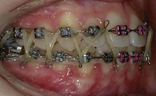
In preadjusted edgewise appliances, the first-, second- and third-order bends are incorporated within the bracket prescription; therefore following tooth alignment the archwire is both flat and straight. This facilitates space closure by simply sliding the teeth along the archwire (Fig. 9.32). The advantages of sliding mechanics are:
Force can be applied using simple elastics, elastomeric chain or coiled nickel titanium springs. However, a significant disadvantage of sliding mechanics is friction between the bracket and archwire as the tooth slides. Any applied force must overcome this before tooth movement can take place.
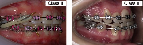
Anchorage support is often required during overjet correction. This can be provided by the use of class II or class III intermaxillary elastics (Fig. 9.33). These will have an extrusive effect on the molar dentition, which can result in a clockwise rotation of the occlusal plane and therefore should be avoided in cases with an increased maxillary–mandibular planes angle.
Finishing
With earlier edgewise systems, considerable time had to be spent at the end of treatment placing artistic bends into the archwires to compensate for the standard bracket placed on each tooth. This was time-consuming and imprecise. With the introduction of preadjusted systems, the bracket prescription does a lot of the work in achieving the correct in/out position, angulation and torque for each tooth relative to its neighbours within the dental arch. Finishing has become less reliant upon wire bending and more of a reflection of correct bracket positioning. However, even with precise bracket positioning, a period of finishing to achieve an optimal aesthetic and occlusal result is often required. This usually involves removing the heavy rectangular steel working archwires, and replacing them with lighter wires that allow some occlusal settling. A good wire for this is beta titanium, which is not as stiff as stainless steel and has excellent formability. This is often supplemented with the use of intermaxillary settling elastics, which help to create maximum interdigitation by gently extruding the teeth (Fig. 9.34).
Begg PR, Kesling PC. Orthodontic Theory and Technique, 3rd edn. Philadelphia: WB Saunders; 1977.
Bennett JC, McLaughlin RP. Orthodontic Management of the Dentition with the Preadjusted Appliance. Oxford: Isis Medical Media; 1997.
Ireland AJ, McDonald F. The Orthodontic Patient: Treatment and Biomechanics. Oxford: Oxford University Press; 2001.
McLaughlin RP, Bennett JC, Trevisi HJ. Systemized Orthodontic Treatment Mechanics. St Louis: Mosby; 2001.
Parkhouse R. Tip-Edge Orthodontics. St Louis: Mosby Elsevier; 2008.
Williams JK, Cook PA, Isaacson KG, et al. Fixed Orthodontic Appliances. Oxford: Wright; 1995.
Alexander CM, Alexander RG, Gorman JC, et al. Lingual orthodontics. A status report. J Clin Orthod. 1982;16:255-262.
Andrews LF. The six keys to normal occlusion. Am J Orthod. 1972;62:296-309.
Andrews LF. The straight-wire appliance. Extraction brackets and ‘classification of treatment’. J Clin Orthod. 1976;10:360-379.
Andrews LF. The straight-wire appliance. Br J Orthod. 1979;6:125-143.
Angle EH. The latest and best in orthodontic mechanisms. Dent Cosmos. 1928;70:1143-1158.
Begg PR. Differential force in orthodontic treatment. Am J Orthod. 1956;42:481-510.
Cadman GR. A vade mecum for the Begg technique: technical principles. Am J Orthod. 1975;67:477-512.
Cadman GR. A vade mecum for the Begg technique: treatment procedures. Am J Orthod. 1975;67:601-624.
Creekmore TD, Kunik RL. Straight wire: the next generation. Am J Orthod Dentofacial Orthop. 1993;104:8-20.
Harradine NW. Self-ligating brackets: where are we now? J Orthod. 2003;30:262-273.
Kapila S, Sachdeva R. Mechanical properties and clinical applications of orthodontic wires. Am J Orthod Dentofacial Orthop. 1989;96:100-109.
Kesling PC. Expanding the horizons of the edgewise arch wire slot. Am J Orthod Dentofacial Orthop. 1988;94:26-37.
Kesling PC, Rocke RT, Kesling CK. Treatment with Tip-Edge brackets and differential tooth movement. Am J Orthod Dentofacial Orthop. 1991;99:387-401.
McLaughlin RP, Bennett JC. [Development of standard Edgewise apparatus for a pre-torqued and pre-angulated bracket system]. Inf Orthod Kieferorthop. 1990;22:149-163.
Parkhouse RC. Rectangular wire and third-order torque: a new perspective. Am J Orthod Dentofacial Orthop. 1998;113:421-430.
Parkhouse RC. Current products and practice: Tip-Edge Plus. J Orthod. 2007;34:59-68.
Roth RH. Five year clinical evaluation of the Andrews straight-wire appliance. J Clin Orthod. 1976;10:836-850.
Russell JS. Aesthetic orthodontic brackets. J Orthod. 2005;32:146-163.
Thickett E, Taylor NG, Hodge T. Choosing a pre-adjusted orthodontic appliance prescription for anterior teeth. J Orthod. 2007;34:95-100.
Wiechmann D. A new bracket system for lingual orthodontic treatment. Part 1: Theoretical background and development. J Orofac Orthop. 2002;63:234-245.