PARANASAL SINUSES

Sinuses
The air-containing cavities situated in the frontal, ethmoidal, and sphenoidal bones of the cranium and the maxillary bones of the face are called the paranasal sinuses because of their formation from the nasal mucosa and their continued communication with the nasal fossae (Figs. 22-1 and 22-2). Although the functions of the sinuses are not agreed on by all anatomists, these cavities are believed to do the following:
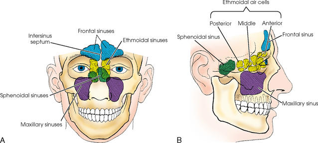
Fig. 22-1 A, Anterior aspect of paranasal sinuses, showing lateral relationship to each other and to surrounding parts. B, Schematic drawing of paranasal sinuses, showing AP relationship to each other and surrounding parts.
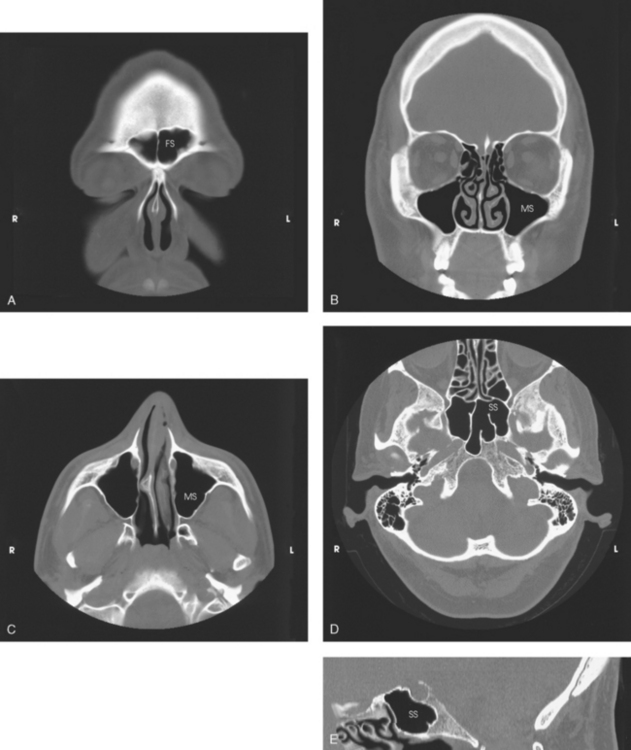
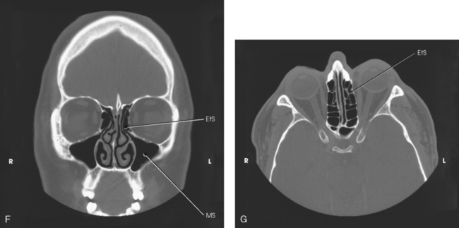
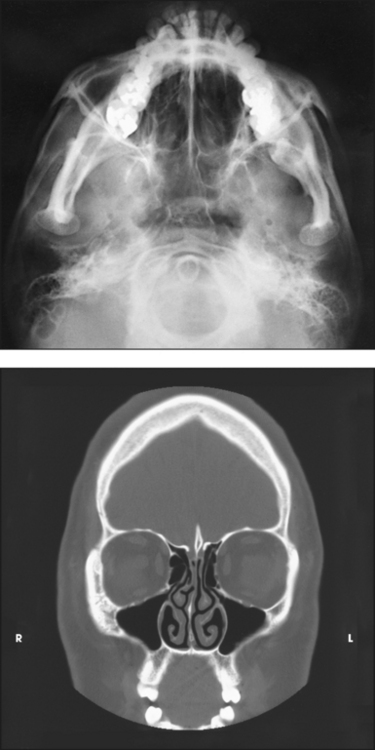
Fig. 22-2 A, Coronal CT image of frontal sinuses (FS). B, Coronal CT scan of maxillary sinuses (MS). C, Axial CT image of MS. D, Axial CT image of sphenoid sinuses (SS). E, Sagittal CT image of SS. F, Coronal CT image of ethmoidal sinuses (EtS). G, Axial CT image of EtS. (From Kelley LL, Petersen CM: Sectional anatomy for imaging professionals, ed 2, St Louis, 2007, Mosby.)
• Serve as a resonating chamber for the voice
• Decrease the weight of the skull by containing air
• Help warm and moisten inhaled air
• Act as shock absorbers in trauma (as airbags do in automobiles)
The sinuses begin to develop early in fetal life, at first appearing as small sacculations of the mucosa of the nasal meatus and recesses. As the pouches, or sacs, grow, they gradually invade the respective bones to form the air sinuses and cells. The maxillary sinuses are usually sufficiently well developed and aerated at birth to be shown radiographically. The other groups of sinuses develop more slowly; by age 6 or 7 years, the frontal and sphenoidal sinuses are distinguishable from the ethmoidal air cells, which they resemble in size and position. The ethmoidal air cells develop during puberty, and the sinuses are not completely developed until age 17 or 18 years. When fully developed, each of the sinuses communicates with the others and with the nasal cavity.
An understanding of the actual size, shape, and position of the sinuses within the skull is made possible by studying the sinuses on computed tomography (CT) head images (see Fig. 22-2).
Maxillary Sinuses
The largest sinuses, the maxillary sinuses, are paired and are located in the body of each maxilla (see Figs. 22-1 and 22-2). Although the maxillary sinuses appear rectangular in the lateral image, they are approximately pyramidal in shape and have only three walls. The apices are directed inferiorly and laterally. The two maxillary sinuses vary considerably in size and shape but are usually symmetric. In adults, each maxillary sinus is approximately 1½ inches (3.5 cm) high and 1 to 1⅓ inches (2.5 to 3 cm) wide. The sinus is often divided into subcompartments by partial septa, and occasionally it is divided into two sinuses by a complete septum. The sinus floor presents several elevations that correspond to the roots of the subjacent teeth. The maxillary sinuses communicate with the middle nasal meatus at the superior aspect of the sinus.
Frontal Sinuses
The frontal sinuses, the second largest sinuses, are paired and are normally located between the tables of the vertical plate of the frontal bone (see Figs. 22-1 and 22-2). The frontal sinuses vary greatly in size and form. Occasionally they are absent. One or both may be approximately ¾ to 1 inch (2 to 2.5 cm) in the vertical or lateral dimension. The sinuses often extend beyond the frontal region of the bone, most frequently into the orbital plates. The intersinus septum is usually deviated from the midline; for this reason, the frontal sinuses are rarely symmetric. Multiple septa are sometimes present. Similar to maxillary sinuses, the frontal sinuses drain into the middle nasal meatus.
Ethmoidal Sinuses
The two ethmoidal sinuses are located within the lateral masses of the labyrinths of the ethmoid bone. They are composed of a varying number of air cells that are divided into three main groups: anterior, middle, and posterior (see Figs. 22-1 and 22-2). The anterior and middle ethmoidal cells range in number from two to eight, and each group opens into the middle nasal meatus. The posterior cells range in number from two to six or more and drain into the superior nasal meatus.
Sphenoidal Sinuses
The sphenoidal sinuses are normally paired and occupy the body of the sphenoid bone (see Figs. 22-1 and 22-2). Anatomists state that often only one sphenoidal sinus is present; however, more than two sphenoidal sinuses are never present. The sphenoidal sinuses vary considerably in size and shape and are usually asymmetric. They lie immediately below the sella turcica and extend between the dorsum sellae and the posterior ethmoidal air cells. The sphenoidal sinuses open into the sphenoethmoidal recess of the nasal cavity.
Technical Considerations
Radiographic density is probably more critical and more misleading in the sinuses than in any other region of the body (Figs. 22-3 to 22-5). Overpenetration of the sinuses diminishes or completely obliterates existing pathologic conditions, and underpenetration can simulate pathologic conditions that do not exist.
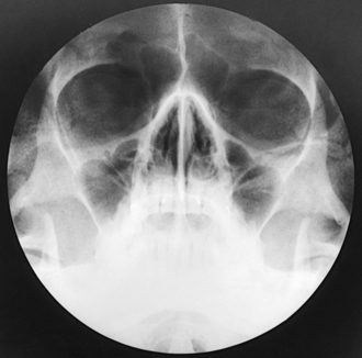
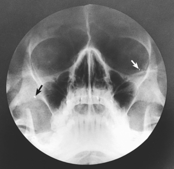
Fig. 22-4 Overexposed radiograph of sinuses showing two artifacts caused by dirt on screens (arrows).
Depending on the technique employed, the milliampere-second (mAs) and kilovolt (peak) (kVp) factors should be balanced so that soft tissue structures and bony structures are shown. Although good contrast is desirable, soft tissue areas may not be visualized with high contrast.
Whenever possible, radiographs of the paranasal sinuses should be made with the patient in the upright position. This position is best for showing the presence or absence of fluid and differentiating between fluid and other pathologic conditions. The value of the upright position in sinus examinations was pointed out by Cross1 and Flecker.2
The paranasal sinuses vary not only in size and form but also in position. The cells of one group frequently encroach on and resemble those of another group. This characteristic of the sinuses, together with their proximity to the vital intracranial organs, makes accurate radiographic demonstration of their anatomic structure of prime importance. The patient’s head must be carefully placed in a sufficient number of positions so that the projections of each group of cavities are as free of superimposed bony structures as possible. The radiographs must be of such quality that it is possible to distinguish the cells of several groups of sinuses and their relationship to the surrounding structures.
Unless sinus radiographs are almost perfect technically, they are of little diagnostic value. For this reason, a precise technical procedure is necessary in radiography of the paranasal sinuses. The first requirements are a small focal spot and clean imaging screens that have perfect contact. The radiographic contrast must similarly distinguish the sinuses from the surrounding structures. The head must be carefully positioned and rigidly immobilized, and respiration must be suspended for the exposures.
The effect of body position and central ray angulation is shown in radiographs of a coconut held in position by head clamps. Fig. 22-6 shows a sharply defined air-fluid level. This coconut was placed in the vertical position, and the central ray was directed horizontally. Fig. 22-7 was also taken with the coconut in the vertical position, but the central ray was directed upward at an angle of 45 degrees to show the gradual fading of the fluid line when the central ray is not horizontal. This effect is much more pronounced in actual practice because of structural irregularities. Fig. 22-8 was made with the coconut in the horizontal position and the central ray directed vertically. The resultant radiograph shows a homogeneous density throughout the cavity of the coconut, with no evidence of an air-fluid level.
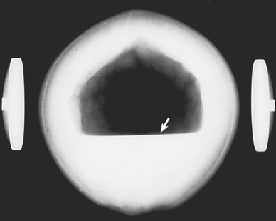
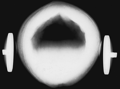
Fig. 22-7 Coconut, vertical position: central ray angled 45 degrees upward. Air-fluid level is not as sharp.
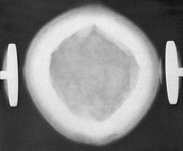
Fig. 22-8 Coconut, horizontal position: vertical central ray. There is no evidence of air-fluid level.
Exudate contained in the sinuses is not fluid in the usual sense of the word but is commonly a heavy, semigelatinous material. The exudate, rather than flowing freely, clings to the walls of the cavity and takes several minutes, depending on its viscosity, to shift position. For this reason, when the position of a patient is changed or the patient’s neck is flexed or extended to position the head for special projections, several minutes should be allowed for the exudate to gravitate to the desired location before the exposure is made.
Although numerous sinus projections are possible, with each serving a special purpose, many are used only when required to show a specific lesion. The consensus is that five standard projections adequately show all of the paranasal sinuses in most patients. The following steps are observed in preparing for these projections:
• Use a suitable protractor to check and adjust the position of the patient’s head to ensure accurate positioning.
• Have the patient remove dentures, hairpins, and ornaments such as earrings and necklaces before proceeding with the examination.
• Because the patient’s face is in contact with the IR holder or the IR itself for many of the radiographs, these items should be cleaned before the patient is positioned.
Even with the most hygienic patients, the hair and face on patients are naturally oily and leave a residue. If a patient is sick, the residue is worse. During positioning of the patient’s head, the hair, mouth, nose, and eyes come in direct contact with the vertical grid device, tabletop, or IR. Medical asepsis can be promoted by placing a paper towel or sheet between the imaging surface and the patient. As standard procedure, the contacted area should be cleaned with a disinfectant before and after positioning.
Radiation Protection
Protection of the patient from unnecessary radiation is a professional responsibility of the radiographer. (See Chapter 1 for specific guidelines.) In this chapter, radiation shielding of the patient is not specified or illustrated because the professional community and the federal government have reported that placing a lead shield over the patient’s pelvis does not significantly reduce gonadal exposure during radiography of the paranasal sinuses. Shielding the abdomen of pregnant women is recommended, however.
Infants and children should be protected by radiation shielding of the thyroid and thymus glands and the gonads. The protective lead shielding used to cover the thyroid and thymus glands can also assist in immobilizing pediatric patients.
The most effective way to protect the patient from unnecessary radiation is to restrict the radiation beam by using proper collimation. Taking care to ensure that the patient is properly instructed and immobilized also reduces the chance of having to repeat the procedure, further limiting the radiation exposure received by the patient.
Paranasal Sinuses
 LATERAL PROJECTION
R or L position
• Rest the side of the patient’s head on the vertical grid device, and adjust the head in a true lateral position. The midsagittal plane of the head is parallel with the plane of the IR, and the interpupillary line is perpendicular to the plane of the IR.
• The infraorbitomeatal line (IOML) is positioned horizontally to ensure proper extension of the head. This position places the IOML perpendicular to front edge of the vertical grid device (Fig. 22-9).
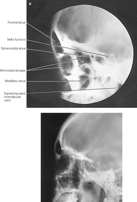
Structures shown: A lateral projection shows the AP and superoinferior dimensions of the paranasal sinuses, their relationship to surrounding structures, and the thickness of the outer table of the frontal bone (Fig. 22-10).
When the lateral projection is to be used for preoperative measurements, it should be made at a 72-inch (183-cm) source–to–image receptor distance to minimize magnification and distortion.
The following should be clearly shown:
 Evidence of proper collimation
All four sinus groups, but the sphenoidal sinus is of primary importance
NOTE: If the patient is unable to assume the upright body position, a lateral projection can be obtained using the dorsal decubitus position. The horizontal beam enables fluid levels to be seen. Positioning of the part is the same except for the IOML, which is vertical rather than horizontal.
Frontal and Anterior Ethmoidal Sinuses
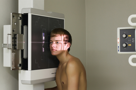
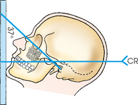
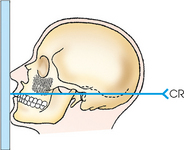
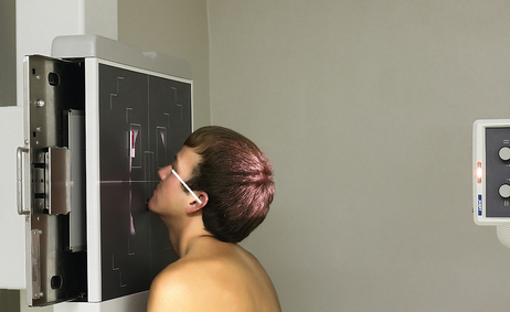
Because sinus images should always be obtained with the patient in the upright body position and a horizontal direction of the central ray, the Caldwell method is easily modified when a head unit or other vertical grid device capable of angular adjustment is used. For the modification, all anatomic landmarks and localization planes remain unchanged.
• Before positioning the patient, tilt the vertical grid device down so that an angle of 15 degrees is obtained (Fig. 22-11, A).
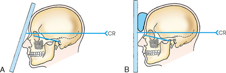
Fig. 22-11 PA axial sinuses: Caldwell method. A, IR tilted 15 degrees. B, Same projection with vertical IR.
• Rest the patient’s nose and forehead on the vertical grid device, and center the nasion to the IR.
• Adjust the midsagittal plane and orbitomeatal line (OML) of the patient’s head perpendicular to the plane of the IR.
• This positioning places the OML perpendicular to the angled IR and 15 degrees from the horizontal central ray.
• When the vertical grid device cannot be angled, extend the patient’s neck slightly, rest the tip of the nose on the grid device, and center the nasion to the IR.
• Position the patient’s head so that the OML forms an angle of 15 degrees with the horizontal central ray. For support, place a radiolucent sponge between the forehead and the grid device (see Figs. 22-11, B, and 22-12).
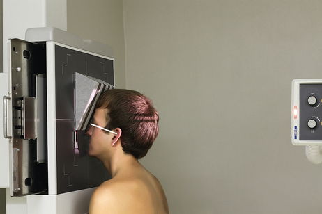
• Adjust the midsagittal plane of the patient’s head perpendicular to the plane of the IR.
• Directed horizontal to exit the nasion. The 15-degree relationship between the central ray and the OML remains the same for both techniques.
NOTE: The angled grid technique is preferred because it brings the IR closer to the sinuses, increasing resolution. Angulation of the grid device provides a natural position for placement of the patient’s nose and forehead.
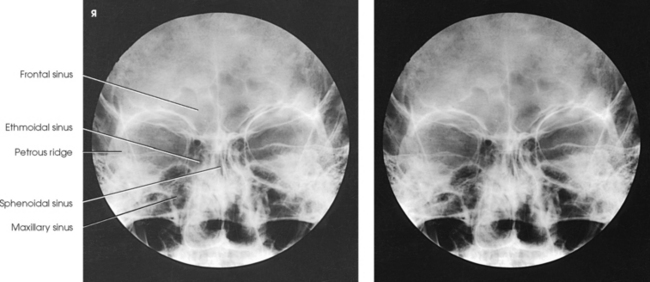
Structures shown: The angled grid technique and vertical grid technique show the frontal sinuses lying superior to the frontonasal suture, the anterior ethmoidal air cells lying on each side of the nasal fossae and immediately inferior to the frontal sinuses, and the sphenoidal sinuses projected through the nasal fossae just inferior to or be-tween the ethmoidal air cells (Fig. 22-13). The dense petrous pyramids extend from the inferior third of the orbit inferiorly to obscure the superior third of the maxillary sinus. This projection is used primarily to show the frontal sinuses and anterior ethmoidal air cells.
The following should be clearly shown:
Evidence of proper collimation
Equal distance between the lateral border of the skull and the lateral border of the orbits, indicating no rotation
Petrous ridge symmetric on both sides
Petrous ridge lying in the lower third of the orbit
Frontal sinuses lying above the frontonasal suture and the anterior ethmoidal air cells lying above the petrous ridges
Frontal and anterior ethmoidal air cells
Maxillary Sinuses
For the Waters method,12 the goal is to hyperextend the patient’s neck just enough to place the dense petrosae immediately below the maxillary sinus floors (Fig. 22-14). When the neck is extended too little, the petrosae are projected over the inferior portions of the maxillary sinuses and obscure underlying pathologic conditions (Fig. 22-15). When the neck is extended too much, the maxillary sinuses are foreshortened, and the antral floors are not shown.
• Because this position is uncomfortable for the patient to hold, have the IR and equipment in position so that the examination can be performed quickly.
• Hyperextend the patient’s neck to approximately the correct position, and then center the IR to the acanthion.
• Rest the patient’s chin on the vertical grid device and adjust it so that the midsagittal plane is perpendicular to the plane of the IR.
• Using a protractor as a guide, adjust the head so that the OML forms an angle of 37 degrees from the plane of the IR (Fig. 22-16; see Fig. 22-14). As a positioning check for the average-shaped skull, the mentomeatal (MML) line should be approximately perpendicular to the IR plane.
Structures shown: The image shows a parietoacanthial projection of the maxillary sinuses, with the petrous ridges lying inferior to the floor of the sinuses (Fig. 22-17). The frontal and ethmoidal air cells are distorted.
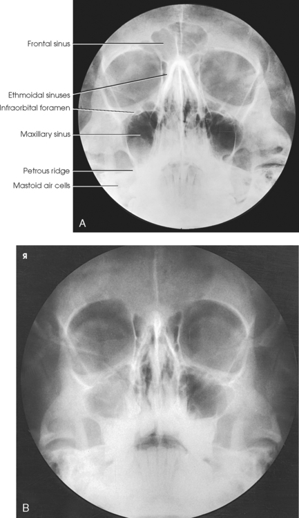
Fig. 22-17 A, Parietoacanthial sinuses: Waters method. B, Same projection. Note clouded (lighter) appearance of right maxillary sinus caused by fluid-filled sinus.
The Waters method is also used to show the foramen rotundum. The images of these structures are seen, one on each side, just inferior to the medial aspect of the orbital floor and superior to the roof of the maxillary sinuses.
The following should be clearly shown:
Evidence of proper collimation
Petrous pyramids lying immediately inferior to the floor of the maxillary sinuses
Equal distance between the lateral border of the skull and the lateral border of the orbit on both sides, indicating no rotation
Orbits and maxillary sinuses symmetric on each side
Maxillary and Sphenoidal Sinuses
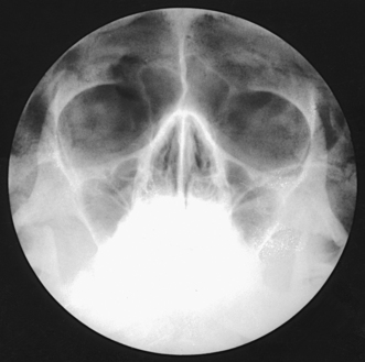
This method provides an excellent demonstration of the sphenoidal sinuses projected through the open mouth. For patients who cannot be placed in position for the submentovertical (SMV) projection, the open-mouth Waters method and lateral projections may be the only techniques to show the sphenoidal sinuses. Because the open-mouth position is uncomfortable for the patient to hold, the radiographer must have the IR and equipment in position to perform the examination quickly.
• Hyperextend the patient’s neck to approximately the correct position, and then position the IR to the acanthion.
• Rest the patient’s chin on the vertical grid device, and adjust it so that the midsagittal plane is perpendicular to the plane of the IR.
• Using a protractor as a guide, adjust the patient’s head so that the OML forms an angle of 37 degrees from the plane of the IR. The MML would not be perpendicular (Fig. 22-18).
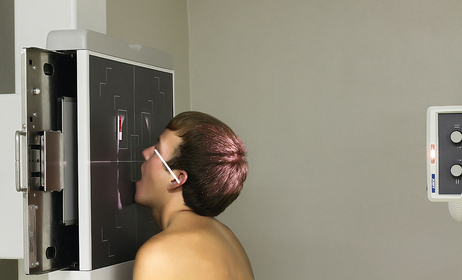
• Have the patient slowly open the mouth wide open while holding the position.
Structures shown: The open-mouth Waters method shows the sphenoidal sinuses projected through the open mouth along with the maxillary sinuses (Fig. 22-19).
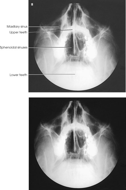
Fig. 22-19 Open-mouth Waters modification shows sphenoidal sinuses projected through open mouth along with maxillary sinuses.
The following should be clearly shown:
Evidence of proper collimation
Petrous pyramids lying immediately inferior to the floor of the maxillary sinuses
Equal distance between the lateral border of the skull and the lateral border of the orbit on both sides, indicating no rotation
Orbits and maxillary sinuses symmetric on each side
Close beam restriction of the sinus area
Ethmoidal and Sphenoidal Sinuses
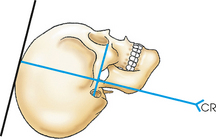
Position of patient: The success of the SMV projection depends on placing the IOML as nearly parallel as possible with the plane of the IR and directing the central ray perpendicular to the IOML. The upright position is recommended for all paranasal sinus radiographs and is more comfortable for the patient. The following steps are observed:
• Use a chair that supports the patient’s back to obtain greater freedom in positioning the patient’s body to place the IOML parallel with the IR.
• Seat the patient far enough away from the vertical grid device so that the head can be fully extended (Figs. 22-20, A, and 22-21).
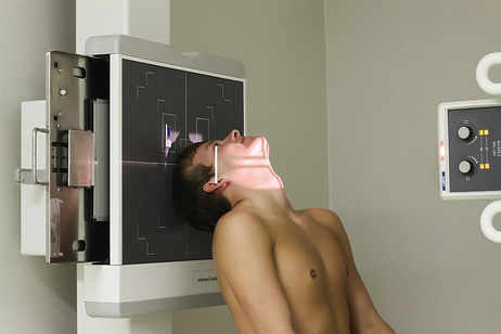
• If necessary to examine short-necked or hypersthenic patients, angle the vertical grid device downward to achieve a parallel relationship between the grid and the IOML (Fig. 22-22; see Fig. 22-20, B). The disadvantage of angling the vertical grid device is that the central ray is not horizontal, and air-fluid levels may not be shown as easily as when the central ray is truly horizontal.
• Hyperextend the patient’s neck as far as possible, and rest the head on its vertex. If the patient’s mouth opens during hyperextension, ask the patient to keep the mouth closed to move the mandibular symphysis anteriorly.
• Adjust the patient’s head so that the midsagittal plane is perpendicular to the midline of the IR.
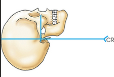
• Adjust the tube so that the central ray is perpendicular to the IOML (see Fig. 22-20).
• Immobilize the patient’s head. In the absence of a head clamp, place a suitably backed strip of adhesive tape across the tip of the chin and anchor it to the sides of the radiographic unit. Do not put the adhesive surface directly on the patient’s skin.
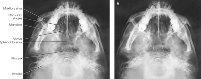
Structures shown: The SMV projection for the sinuses shows a symmetric image of the anterior portion of the base of the skull. The sphenoidal sinus and ethmoidal air cells are shown (Fig. 22-23).
The following should be clearly shown:
Evidence of proper collimation
Equal distance from the lateral border of the skull to the mandibular condyles on both sides, indicating that the midsagittal plane is perpendicular (no tilt)
Anterior frontal bone superimposed by mental protuberance, indicating that the IOML is parallel (full extension)
1Cross KS: Radiography of the nasal accessory sinuses, Med J Aust 14:569, 1927.
2Flecker H: Roentgenograms of the antrum, AJR Am J Roentgenol 20:56, 1928 (letter).
1,Waters CA: A modification of the occipitofrontal position in the roentgen examination of the accessory nasal sinuses, Arch Radiol Ther 20:15, 1915.
2Mahoney HO: Head and sinus positions, Xray Techn 1:89, 1930.