SKULL
SUMMARY OF PROJECTIONS
Skull
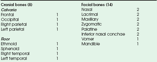
The skull rests on the superior aspect of the vertebral column. It is composed of 22 separate bones divided into two distinct groups: 8 cranial bones and 14 facial bones. The cranial bones are divided further into the calvaria and floor (Box 20-1). The cranial bones form a protective housing for the brain. The facial bones provide structure, shape, and support for the face. They also form a protective housing for the upper ends of the respiratory and digestive tracts and, with several of the cranial bones, form the orbital sockets for protection of the organs of sight. The hyoid bone is commonly discussed with this group of bones.
The bones of the skull are identified in Figs. 20-1 to 20-3. The 22 primary bones of the skull should be located and recognized in the different views before they are studied in greater detail.
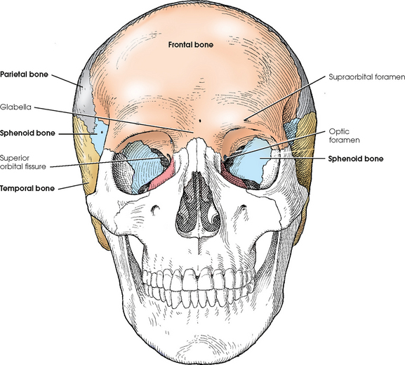
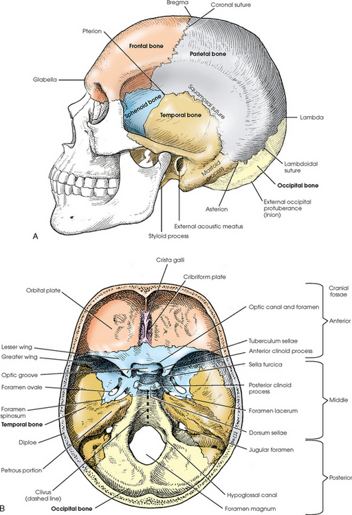
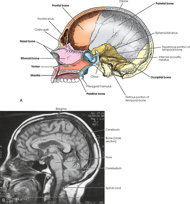
Fig. 20-3 A, Lateral aspect of interior of cranium. B, Sagittal MRI of cranium showing contents and position of brain. Note bony protective housing.
The bones of the cranial vault are composed of two plates of compact tissue separated by an inner layer of spongy tissue called diploë. The outer plate, or table, is thicker than the inner table over most of the vault, and the thickness of the layer of spongy tissue varies considerably.
Except for the mandible, the bones of the cranium and face are joined by fibrous joints called sutures. The sutures are named coronal, sagittal, squamosal, and lambdoidal (see Figs. 20-1 and 20-2). The coronal suture is found between the frontal and parietal bones. The sagittal suture is located on the top of the head between the two parietal bones and just behind the coronal suture line (not visible in Figs. 20-1 and 20-2). The junction of the coronal and sagittal sutures is the bregma. Between the temporal bones and the parietal bones are the squamosal sutures. Between the occipital bone and the parietal bones is the lambdoidal suture. The lambda is the junction of the lambdoidal and sagittal sutures. On the lateral aspect of the skull, the junction of the parietal bone, squamosal suture, and greater wing of the sphenoid is the pterion, which overlies the middle meningeal artery. At the junction of the occipital bone, parietal bone, and mastoid portion of the temporal bone is the asterion.
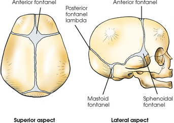
In a newborn infant, the bones of the cranium are thin and not fully developed. They contain a small amount of calcium, are indistinctly marked, and present six areas of incomplete ossification called fontanels (Fig. 20-4). Two of the fontanels are situated in the midsagittal plane at the superior and posterior angles of the parietal bones. The anterior fontanel is located at the junction of the two parietal bones and the one frontal bone at the bregma. Posteriorly and in the midsagittal plane is the posterior fontanel, located at the point labeled lambda in Fig. 20-2. Two fontanels are also on each side at the inferior angles of the parietal bones. Each sphenoidal fontanel is found at the site of the pterion; the mastoid fontanels are found at the asteria. The posterior and sphenoidal fontanels normally close in the 1st and 3rd months after birth, and the anterior and mastoid fontanels close during the 2nd year of life.
The cranium develops rapidly in size and density during the first 5 or 6 years, after which a gradual increase occurs until adult size and density are achieved, usually by the age of 12 years. The thickness and degree of mineralization in normal adult crania show comparatively little difference in radiopacity from person to person, and the atrophy of old age is less marked than in other regions of the body.
Internally, the cranial floor is divided into three regions: the anterior, middle, and posterior cranial fossae (see Fig. 20-2, B). The anterior cranial fossa extends from the anterior frontal bone to the lesser wings of the sphenoid. It is associated mainly with the frontal lobes of the cerebrum. The middle cranial fossa accommodates the temporal lobes and associated neurovascular structures and extends from the lesser wings of the sphenoid bone to the apices of the petrous portions of the temporal bones. The deep depression posterior to the petrous ridges is the posterior cranial fossa, which protects the cerebellum, pons, and medulla oblongata (see Fig. 20-3, B).
The average or so-called normal cranium is more or less oval in shape, wider in back than in front. The average cranium measures approximately 6 inches (15 cm) at its widest point from side to side, 7 inches (17.8 cm) at its longest point from front to back, and 9 inches (22 cm) at its deepest point from the vertex to the submental region. Crania vary in size and shape, with resultant variation in the position and relationship of internal parts.
Internal deviations from the norm are usually indicated by external deviations and can be estimated with a reasonable degree of accuracy. The length and width of the normally shaped head vary by 1 inch (2.5 cm). Any deviation from this relationship indicates a comparable change in the position and relationship of the internal structures. If the deviation involves more than a 5-degree change, it must be compensated for by a change in either part rotation or central ray angulation. This “rule” applies to all images except direct lateral projections. A ½-inch (1.3 cm) change in the 1-inch (2.5-cm) width-to-length measurement indicates an approximately 5-degree change in the direction of the internal parts with reference to the midsagittal plane.
It is important for the radiographer to understand cranial anatomy from the standpoint of the size, shape, position, and relationship of the component parts of the cranium so that estimations and compensations can be made for deviations from the norm.
Cranial Bones
The frontal bone has a vertical portion and horizontal portions. The vertical portion, called the frontal squama, forms the forehead and the anterior part of the vault. The horizontal portions form the orbital plates (roofs of the orbits), part of the roof of the nasal cavity, and the greater part of the anterior cranial fossa (Figs. 20-5 to 20-7).
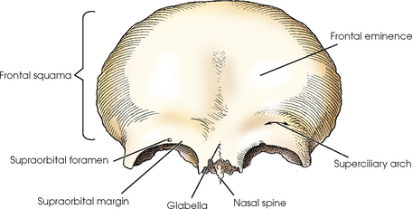
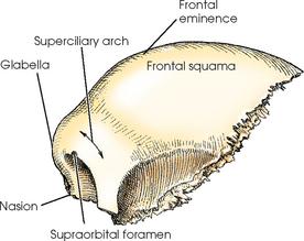
On each side of the midsagittal plane of the superior portion of the squama is a rounded elevation called the frontal eminence. Below the frontal eminences, just above the supraorbital margins, are two arched ridges that correspond in position to the eyebrows. These ridges are called the superciliary arches. In the center of the supraorbital margin is an opening for nerves and blood vessels called the supraorbital foramen. The smooth elevation between the superciliary arches is termed the glabella.
The frontal sinuses (see Chapter 22) are situated between the two tables of the squama on each side of the midsagittal plane. These irregularly shaped sinuses are separated by a bony wall, which may be incomplete and usually deviates from the midline.
The squama articulates with the parietal bones at the coronal suture, the greater wing of the sphenoid bone at the frontosphenoidal suture, and the nasal bones at the frontonasal suture. The midpoint of the frontonasal suture is termed the nasion.
The frontal bone articulates with the right and left parietals, the sphenoid, and the ethmoid bones of the cranium.
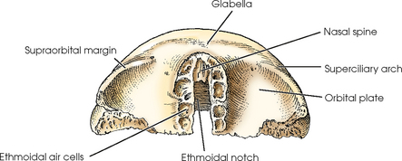
The orbital plates of the horizontal portion of the frontal bone are separated by a notch called the ethmoidal notch. This notch receives the cribriform plate of the ethmoid bone. At the anterior edge of the ethmoidal notch is a small inferior projection of bone, the nasal spine, which is the superiormost component of the bony nasal septum. The posterior margins of the orbital plates articulate with the lesser wings of the sphenoid bone.
ETHMOID BONE
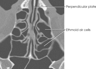
The ethmoid bone is a small, cube-shaped bone that consists of a horizontal plate; a vertical plate; and two light, spongy lateral masses called labyrinths (Figs. 20-8 to 20-11). Situated between the orbits, the ethmoid bone forms part of the anterior cranial fossa, the nasal cavity and orbital walls, and the bony nasal septum.
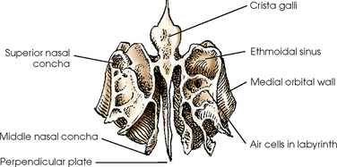
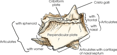
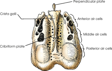
The horizontal portion of the ethmoid bone, called the cribriform plate, is received into the ethmoidal notch of the frontal bone. The cribriform plate is perforated by many foramina for the transmission of olfactory nerves. The plate also has a thick, conical process, the crista galli, which projects superiorly from its anterior midline and serves as the anterior attachment for the falx cerebri.
The vertical portion of the ethmoid bone is called the perpendicular plate. This plate is a thin, flat bone that projects inferiorly from the inferior surface of the cribriform plate and, with the nasal spine, forms the superior portion of the bony septum of the nose.
The labyrinths contain the ethmoidal sinuses, or air cells. The cells of each side are arbitrarily divided into three groups: the anterior, middle, and posterior ethmoidal air cells. The walls of the labyrinths form a part of the medial walls of the orbits and a part of the lateral walls of the nasal cavity. Projecting inferiorly from each medial wall of the labyrinths are two thin, scroll-shaped processes called the superior and middle nasal conchae.
The ethmoid bone articulates with the frontal and sphenoid bones of the cranium.
PARIETAL BONES
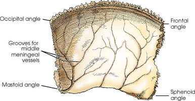
The two parietal bones are square and have a convex external surface and a concave internal surface (Figs. 20-12 and 20-13). The parietal bones form a large portion of the sides of the cranium. They also form the posterior portion of the cranial roof by their articulation with each other at the sagittal suture in the midsagittal plane.
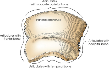
Each parietal bone presents a prominent bulge, called the parietal eminence, near the central portion of its external surface. In radiography, the width of the head should be measured at this point because it is the widest point of the head.
Each parietal bone articulates with the frontal, temporal, occipital, sphenoid, and opposite parietal bone of the cranium.
SPHENOID BONE
The sphenoid bone is an irregularly wedge-shaped bone that resembles a bat with its wings extended. It is situated in the base of the cranium anterior to the temporal bones and basilar part of the occipital bone (Figs. 20-14 to 20-16). The sphenoid bone consists of a body; two lesser wings and two greater wings, which project laterally from the sides of the body; and two pterygoid processes, which project inferiorly from each side of the inferior surface of the body.
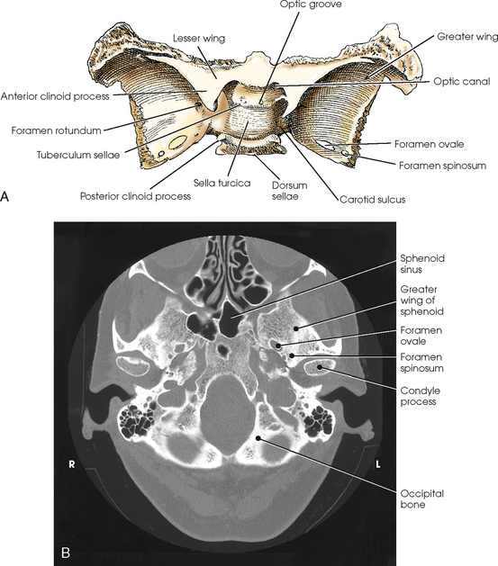
Fig. 20-14 A, Superior aspect of sphenoid bone. B, Axial CT scan of sphenoid bone. (B, From Kelley LL, Petersen CM: Sectional anatomy for imaging professionals, ed 2, St Louis, 2007, Mosby.)
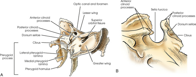
Fig. 20-15 A, Oblique aspect of upper and lateroposterior aspects of sphenoid bone (right lateral pterygoid lamina removed). B, Sella turcica of sphenoid bone, lateral view.
The body of the sphenoid bone contains the two sphenoidal sinuses, which are incompletely separated by a median septum. The anterior surface of the body forms the posterior bony wall of the nasal cavity. The superior surface presents a deep depression called the sella turcica and contains a gland called the pituitary gland. The sella turcica lies in the midsagittal plane of the cranium at a point ¾ inch (1.9 cm) anterior to and ¾ inch (1.9 cm) superior to the level of the external acoustic meatus (EAM). The sella turcica is bounded anteriorly by the tuberculum sellae and posteriorly by the dorsum sellae, which bears the posterior clinoid processes. The slanted area of bone posterior and inferior to the dorsum sellae is continuous with the basilar portion of the occipital bone and is called the clivus. The clivus supports the pons. On either side of the sella turcica is a groove, the carotid sulcus, in which the internal carotid artery and cavernous sinus lie.
The optic groove extends across the anterior portion of the tuberculum sellae. The groove ends on each side at the optic canal. The optic canal is the opening into the apex of the orbit for the transmission of the optic nerve and ophthalmic artery. The actual opening is called the optic foramen.
The lesser wings are triangular in shape and nearly horizontal in position. They arise, one on each side, from the anterosuperior portion of the body of the sphenoid bone and project laterally, ending in sharp points. The lesser wings form the posteromedial portion of the roofs of the orbits, the posterior portion of the anterior cranial fossa, the upper margin of the superior orbital fissures, and the optic canals. The medial ends of their posterior borders form the anterior clinoid processes. Each process arises from two roots. The anterior (superior) root is thin and flat, and the posterior (inferior) root, referred to as the sphenoid strut, is thick and rounded. The circular opening between the two roots is the optic canal.
The greater wings arise from the sides of the body of the sphenoid bone and curve laterally, posteriorly, anteriorly, and superiorly. The greater wings form a part of the middle cranial fossa, the posterolateral walls of the orbits, the lower margin of the superior orbital sulci, and the greater part of the posterior margin of the inferior orbital sulci. The foramina rotundum, ovale, and spinosum are paired and are situated in the greater wings. Because these foramina transmit nerves and blood vessels, they are subject to radiologic investigation for the detection of erosive lesions of neurogenic or vascular origin.
The pterygoid processes arise from the lateral portions of the inferior surface of the body of the sphenoid bone and the medial portions of the inferior surfaces of the greater wings. These processes project inferiorly and curve laterally. Each pterygoid process consists of two plates of bone, the medial and lateral pterygoid laminae, which are fused at their superoanterior parts. The inferior extremity of the medial lamina possesses an elongated, hook-shaped process, the pterygoid hamulus, which makes it longer and narrower than the lateral lamina. The pterygoid processes articulate with the palatine bones anteriorly and with the wings of the vomer, where they enter into the formation of the nasal cavity.
The sphenoid bone articulates with each of the other seven bones of the cranium.
OCCIPITAL BONE
The occipital bone is situated at the posteroinferior part of the cranium. It forms the posterior half of the base of the cranium and the greater part of the posterior cranial fossa (Figs. 20-17 to 20-19). The occipital bone has four parts: the squama, which is saucer-shaped, being convex externally; two occipital condyles, which extend anteriorly, one on each side of the foramen magnum; and the basilar portion. The occipital bone also has a large aperture, the foramen magnum, through which the inferior portion of the medulla oblongata passes as it exits the cranial cavity and joins the spinal cord.
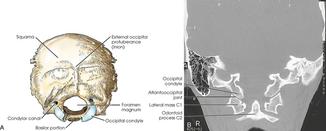
Fig. 20-17 A, External surface of occipital bone. B, Coronal MRI showing atlantooccipital joint. (B, Courtesy Siemens Medical Systems, Iselin, NJ.)
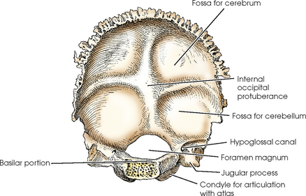
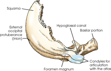
The squama curves posteriorly and superiorly from the foramen magnum and is curved from side to side. It articulates with the parietal bones at the lambdoidal suture and with the mastoid portions of the temporal bones at the occipitomastoid sutures. On the external surface of the squama, midway between its summit and the foramen magnum, is a prominent process termed the external occipital protuberance, or inion, that corresponds in position with the internal occipital protuberance.
The occipital condyles project anteriorly, one from each side of the squama, for articulation with the atlas of the cervical spine. Part of each lateral portion curves medially to fuse with the basilar portion and complete the foramen magnum, and part of it projects laterally to form the jugular process. On the inferior surface of the curved parts, extending from the level of the middle of the foramen magnum anteriorly to the level of its anterior margin, reciprocally shaped condyles articulate with the superior facets of the atlas. These articulations, known as the occipitoatlantal joints, are the only bony articulations between the skull and the neck. The hypoglossal canals are found at the anterior ends of the condyles and transmit the hypoglossal nerves. At the posterior end of the condyles are the condylar canals, through which the emissary veins pass. The anterior portion of the occipital bone contains a deep notch that forms a part of the jugular foramen (see Fig. 20-2, B). The jugular foramen is an important large opening in the skull for two reasons: It allows blood to drain from the brain via the internal jugular vein, and it lets three cranial nerves pass through it.
The basilar portion of the occipital bone curves anteriorly and superiorly to its junction with the body of the sphenoid. In an adult, the basilar part of the occipital bone fuses with the body of the sphenoid bone, resulting in the formation of a continuous bone. The sloping surface of this junction between the dorsum sellae of the sphenoid bone and the basilar portion of the occipital bone is called the clivus.
The occipital bone articulates with the two parietals, the two temporal bones and the sphenoid of the cranium, and the first cervical vertebra.
TEMPORAL BONES
The temporal bones are irregular in shape and are situated on each side of the base of the cranium between the greater wings of the sphenoid bone and the occipital bone (Figs. 20-20 to 20-24). The temporal bones form a large part of the middle fossa of the cranium and a small part of the posterior fossa. Each temporal bone consists of a squamous portion, a tympanic portion, a styloid process, a zygomatic process, and a petromastoid portion (the mastoid and petrous portions) that contains the organs of hearing and balance.
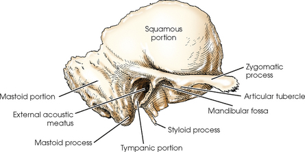
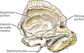
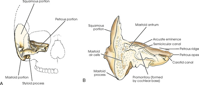
Fig. 20-22 A, Anterior aspect of temporal bone in relation to surrounding structures. B, Coronal section through mastoid and petrous portions of temporal bone.
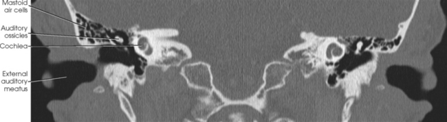
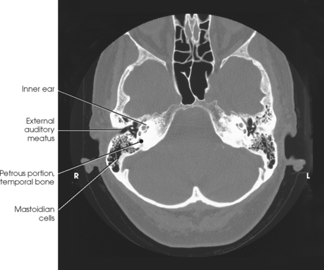
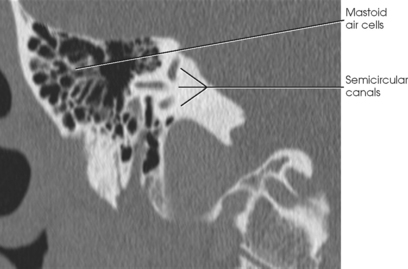
Fig. 20-24 Axial CT scan of petrous portion at level of external auditory meatus. (From Kelley LL, Petersen CM: Sectional anatomy for imaging professionals, ed 2, St Louis, 2007, Mosby.)
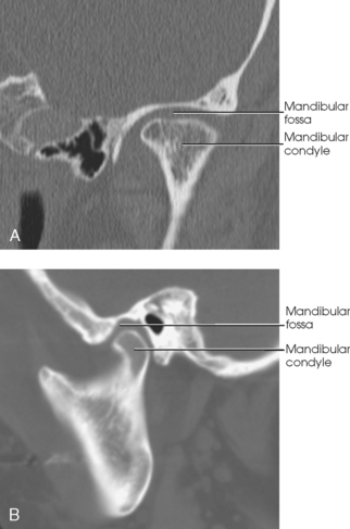
The squamous portion is the thin upper portion of the temporal bone. It forms a part of the side wall of the cranium and has a prominent arched process, the zygomatic process, which projects anteriorly to articulate with the zygomatic bone of the face and complete the zygomatic arch. On the inferior border of the zygomatic process is a rounded eminence, the articular tubercle, which forms the anterior boundary of the mandibular fossa. The mandibular fossa receives the condyle of the mandible to form the temporomandibular joint (TMJ).
The tympanic portion is situated below the squama and in front of the mastoid and petrous portions of the temporal bone. This portion forms the anterior wall, inferior wall, and part of the posterior walls of the EAM. The EAM is approximately ½ inch (1.3 cm) in length and projects medially, anteriorly, and slightly superiorly.
The styloid process, a slender, pointed bone of variable length, projects inferiorly, anteriorly, and slightly medially from the inferior portion of the tympanic part of the temporal bone.
Petromastoid portion
The petrous and mastoid portions together are called the petromastoid portion. The mastoid portion, which forms the inferior, posterior part of the temporal bone, is prolonged into the conical mastoid process (see Figs. 20-22 and 20-24).
The mastoid portion articulates with the parietal bone at its superior border through the parietomastoid suture and with the occipital bone at its posterior border through the occipitomastoid suture, which is contiguous with the lambdoidal suture. The mastoid process varies considerably in size, depending on its pneumatization, and is larger in males than in females.
The first of the mastoid air cells to develop is situated at the upper anterior part of the process and is termed the mastoid antrum. This air cell is quite large and communicates with the tympanic cavity. Shortly before or after birth, smaller air cells begin to develop around the mastoid antrum and continue to increase in number and size until around puberty. The air cells vary considerably in size and number. Occasionally, they are absent altogether, in which case the mastoid process is solid bone and is usually small.
The petrous portion, often called the petrous pyramid, is conical or pyramidal and is the thickest, densest bone in the cranium. This part of the temporal bone contains the organs of hearing and balance. From its base at the squamous and mastoid portions, the petrous portion projects medially and anteriorly between the greater wing of the sphenoid bone and the occipital bone to the body of the sphenoid bone, with which its apex articulates. The internal carotid artery in the carotid canal enters the inferior aspect of the petrous portion, passes superior to the cochlea, then passes medially to exit the petrous apex. Near the petrous apex is a ragged foramen called the foramen lacerum. The carotid canal opens into this foramen, which contains the internal carotid artery (see Fig. 20-2, B). At the center of the posterior aspect of the petrous portion is the internal acoustic meatus (IAM), which transmits the vestibulocochlear and facial nerves. The upper border of the petrous portion is commonly referred to as the petrous ridge. The top of the ridge lies approximately at the level of an external radiography landmark called the top of ear attachment (TEA).
The temporal bone articulates with the parietal, occipital, and sphenoid bones of the cranium.
Ear
The ear is the organ of hearing and balance (Fig. 20-25). The essential parts of the ear are housed in the petrous portion of the temporal bone. The organs of hearing and equilibrium consist of three main divisions: the external ear, middle ear, and internal ear.

Fig. 20-25 A, Frontal view of face showing internal structures of ear (shaded area). B, External, middle, and internal ear.
EXTERNAL EAR
The external ear consists of two parts: (1) the auricle, the oval-shaped, fibrocartilaginous, sound-collecting organ situated on the side of the head, and (2) the external acoustic meatus (EAM), a sound-conducting canal. The superior attachment of the auricle is the top of ear attachment (TEA). The TEA is a reference point for positioning the lateral cervical spine. The auricle has a deep central depression, the concha, the lower part of which leads into the EAM. At its anterior margin, the auricle has a prominent cartilaginous lip, the tragus, which projects posteriorly over the entrance of the meatus. The outer rim of the ear is the helix. The EAM is about 1 inch (2.5 cm) long. The outer third of the canal wall is cartilaginous, and the inner two thirds are osseous. From the meatal orifice, the canal forms a slight curve as it passes medially and anteriorly in line with the axis of the IAM. The EAM ends at the tympanic membrane of the middle ear.
MIDDLE EAR
The middle ear is situated between the external ear and internal ear. The middle ear proper consists of (1) the tympanic membrane (or eardrum); (2) an irregularly shaped, air-containing compartment called the tympanic cavity; and (3) three small bones called the auditory ossicles (Fig. 20-26). The middle ear communicates with the mastoid antrum and auditory eustachian tube.
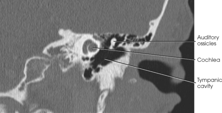
Fig. 20-26 Coronal CT scan through petrous portion of temporal bone showing middle and inner ear. (Courtesy Karl Mockler, RT[R].)
The tympanic membrane is a thin, concavoconvex, membranous disk with an elliptic shape. The disk, the convex surface of which is directed medially, is situated obliquely over the medial end of the EAM and serves as a partition between the external ear and middle ear. The function of the tympanic membrane is the transmission of sound vibrations.
The tympanic cavity is a narrow, irregularly shaped chamber that lies just posterior and medial to the mandibular fossa. The cavity is separated from the external ear by the tympanic membrane and from the internal ear by the bony labyrinth. The tympanic cavity communicates with the nasopharynx through the auditory (eustachian) tube, a passage by which air pressure in the middle ear is equalized with the pressure in the outside air passages. The auditory tube is about 1¼ inches (3 cm) long. From its entrance into the tympanic cavity, the auditory tube passes medially and inferiorly to its orifice on the lateral wall of the nasopharynx.
The mastoid antrum is the large air cavity situated in the temporal bone above the mastoid air cells and immediately behind the posterior wall of the middle ear.
The auditory ossicles, named for their shape, are the malleus (hammer), incus (anvil), and stapes (stirrup). These three delicate bones are articulated to permit vibratory motion. They bridge the middle ear cavity for the transmission of sound vibrations from the tympanic membrane to the internal ear. The handle of the malleus (the outermost ossicle) is attached to the tympanic membrane, and its head articulates with the incus (the central ossicle). The head of the stapes (the innermost ossicle) articulates with the incus, and its base is fitted into the oval window of the inner ear.
INTERNAL EAR
The internal ear contains the essential sensory apparatus of hearing and equilibrium and lies on the densest portion of the petrous portion immediately below the arcuate eminence. Composed of an irregularly shaped bony chamber called the bony labyrinth, the internal ear is housed within the bony chamber and is an intercommunicating system of ducts and sacs known as the membranous labyrinth. The bony labyrinth consists of three distinctly shaped parts: (1) a spiral-coiled, tubular part called the cochlea, which communicates with the middle ear through the membranous covering of the round window (see Fig. 20-26); (2) a small, ovoid central compartment behind the cochlea, known as the vestibule, which communicates with the middle ear via the oval window; and (3) three unequally sized semicircular canals that form right angles to one another and are called, according to their positions, the anterior, posterior, and lateral semicircular canals (Fig. 20-27). From its cranial orifice, the internal acoustic meatus (IAM) passes inferiorly and laterally for a distance of about ½ inch (1.3 cm). Through this canal, the cochlear and vestibular nerves pass from their fibers in the respective parts of the membranous labyrinth to the brain. The cochlea is used for hearing, and the vestibule and semicircular canals are involved with equilibrium.
Facial Bones
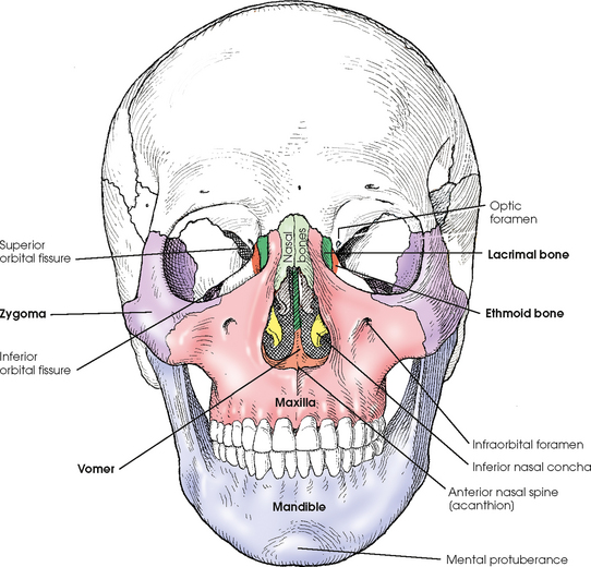
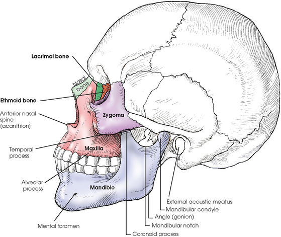
The two small, thin nasal bones vary in size and shape in different individuals (Figs. 20-28 and 20-29). They form the superior bony wall (called the bridge of the nose) of the nasal cavity. The nasal bones articulate in the midsagittal plane, where at their posterosuperior surface they also articulate with the perpendicular plate of the ethmoid bone. They articulate with the frontal bone above and with the maxillae at the sides.
LACRIMAL BONES
The two lacrimal bones, which are the smallest bones in the skull, are very thin and are situated at the anterior part of the medial wall of the orbits between the labyrinth of the ethmoid bone and the maxilla (see Figs. 20-28 and 20-29). Together with the maxillae, the lacrimal bones form the lacrimal fossae, which accommodate the lacrimal sacs. Each lacrimal bone contains a lacrimal foramen through which a tear duct passes. Each lacrimal bone articulates with the frontal and ethmoid cranial bones and the maxilla and inferior nasal concha facial bones. The lacrimal bones can be seen on PA and lateral projections of the skull.
MAXILLARY BONES
The two maxillary bones are the largest of the immovable bones of the face (see Figs. 20-28 and 20-29). Each articulates with all other facial bones except the mandible. Each also articulates with the frontal and ethmoid bones of the cranium. The maxillary bones form part of the lateral walls and most of the floor of the nasal cavity, part of the floor of the orbital cavities, and three fourths of the roof of the mouth. Their zygomatic processes articulate with the zygomatic bones and assist in the formation of the prominence of the cheeks. The body of each maxilla contains a large, pyramidal cavity called the maxillary sinus, which empties into the nasal cavity. An infraorbital foramen is located under each orbit and serves as a passage through which the infraorbital nerve and artery reach the nose.
At their inferior borders, the maxillae possess a thick, spongy ridge called the alveolar process, which supports the roots of the teeth. In the anterior midsagittal plane at their junction with each other, the maxillary bones form a pointed, forward-projecting process called the anterior nasal spine. The midpoint of this prominence is called the acanthion.
ZYGOMATIC BONES
The zygomatic bones form the prominence of the cheeks and a part of the side wall and floor of the orbital cavities (see Figs. 20-28 and 20-29). A posteriorly extending temporal process unites with the zygomatic process of the temporal bone to form the zygomatic arch. The zygomatic bones articulate with the frontal bone superiorly, with the zygomatic process of the temporal bone at the side, with the maxilla anteriorly, and with the sphenoid bone posteriorly.
PALATINE BONES
The two palatine bones are L-shaped bones composed of vertical and horizontal plates. The horizontal plates articulate with the maxillae to complete the posterior fourth of the bony palate, or roof of the mouth (see Fig. 20-3). The vertical portions of the palatine bones extend upward between the maxillae and the pterygoid processes of the sphenoid bone in the posterior nasal cavity. The superior tips of the vertical portions of the palatine bones assist in forming the posteromedial bony orbit.
INFERIOR NASAL CONCHAE
The inferior nasal conchae extend diagonally and inferiorly from the lateral walls of the nasal cavity at approximately its lower third (see Fig. 20-28). They are long, narrow, and extremely thin; they curl laterally, which gives them a scroll-like appearance.
The upper two nasal conchae are processes of the ethmoid bone. The three nasal conchae project into and divide the lateral portion of the respective sides of the nasal cavity into superior, middle, and inferior meatus. They are covered with a mucous membrane to warm, moisten, and cleanse inhaled air.
VOMER
The vomer is a thin plate of bone situated in the midsagittal plane of the floor of the nasal cavity, where it forms the inferior part of the nasal septum (see Fig. 20-28). The anterior border of the vomer slants superiorly and posteriorly from the anterior nasal spine to the body of the sphenoid bone, with which its superior border articulates. The superior part of its anterior border articulates with the perpendicular plate of the ethmoid bone; its posterior border is free.
MANDIBLE
The mandible, the largest and densest bone of the face, consists of a curved horizontal portion, called the body, and two vertical portions, called the rami, which unite with the body at the angle of the mandible, or gonion (Fig. 20-30). At birth, the mandible consists of bilateral pieces held together by a fibrous symphysis that ossifies during the first year of life. At the site of ossification is a slight ridge that ends below in a triangular prominence, the mental protuberance. The symphysis is the most anterior and central part of the mandible. This is where the left and right halves of the mandible have fused.
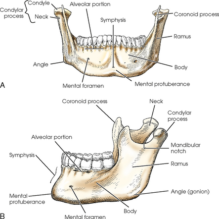
The superior border of the body of the mandible consists of spongy bone, called the alveolar portion, which supports the roots of the teeth. Below the second premolar tooth, approximately halfway between the superior and inferior borders of the bone, is a small opening on each side for the transmission of nerves and blood vessels. These two openings are called the mental foramina.
The rami project superiorly at an obtuse angle to the body of the mandible, and their broad surface forms an angle of approximately 110 to 120 degrees. Each ramus presents two processes at its upper extremity, one coronoid and one condylar, which are separated by a concave area called the mandibular notch. The anterior process, the coronoid process, is thin and tapered and projects to a higher level than the posterior process. The condylar process consists of a constricted area, the neck, above which is a broad, thick, almost transversely placed condyle that articulates with the mandibular fossa of the temporal bone (Fig. 20-31). This articulation, the TMJ, slants posteriorly approximately 15 degrees and inferiorly and medially approximately 15 degrees. Radiographic projections, produced from the opposite side, must reverse these directions. In other words, the central ray angulation must be superior and anterior to coincide with the long axis of the joint. The TMJ is situated immediately in front of the EAM.
HYOID BONE
The hyoid bone is a small, U-shaped structure situated at the base of the tongue, where it is held in position in part by the stylohyoid ligaments extending from the styloid processes of the temporal bones (Fig. 20-32). Although the hyoid bone is an accessory bone of the axial skeleton, it is described in this chapter because of its connection with the temporal bones. The hyoid is the only bone in the body that does not articulate with any other bone.
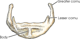
The hyoid bone is divided into a body, two greater cornua, and two lesser cornua. The bone serves as an attachment for certain muscles of the larynx and tongue and is easily palpated just above the larynx.
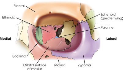
ORBITS
Each orbit is composed of seven different bones (Fig. 20-33). Three of these are cranial bones: frontal, sphenoid, and ethmoid. The other four bones are the facial bones: maxilla, zygoma, lacrimal, and palatine. The circumference of the orbit, or outer rim area, is composed of three of the seven bones—the frontal, zygoma, and maxilla. The remaining four bones compose most of the posterior aspect of the orbit.
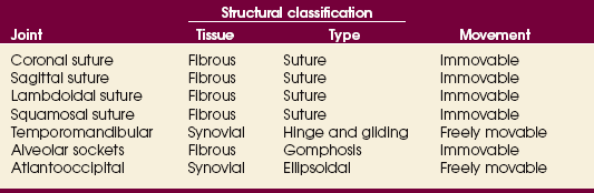
Articulations of the Skull
The sutures of the skull are connected by toothlike projections of bone interlocked with a thin layer of fibrous tissue. These articulations allow for no movement and are classified as fibrous joints of the suture type. The articulations of the facial bones, including the joints between the roots of the teeth and the jawbones, are fibrous gomphoses. The exception is the point at which the rounded condyle of the mandible articulates with the mandibular fossa of the temporal bone to form the TMJ. The TMJ articulation is a synovial joint of the hinge and gliding type. The atlantooccipital joint is a synovial ellipsoidal joint that joins the base of the skull (occipital bone) with the atlas of the cervical spine. The seven joints of the skull are summarized in Table 20-1.
SUMMARY OF PATHOLOGY
| Condition | Definition |
| Fracture | Disruption in continuity of bone |
| Basal | Fracture located at the base of the skull |
| Blowout | Fracture of the floor of the orbit |
| Contre-coup | Fracture to one side of a structure caused by trauma to the other side |
| Depressed | Fracture causing a portion of the skull to be depressed into the cranial cavity |
| Le Fort | Bilateral horizontal fractures of the maxillae |
| Linear | Irregular or jagged fracture of the skull |
| Tripod | Fracture of the zygomatic arch and orbital floor or rim and dislocation of the frontozygomatic suture |
| Mastoiditis | Inflammation of the mastoid antrum and air cells |
| Metastases | Transfer of cancerous lesion from one area to another |
| Osteomyelitis | Inflammation of bone owing to a pyogenic infection |
| Osteopetrosis | Increased density of atypically soft bone |
| Osteoporosis | Loss of bone density |
| Paget disease | Thick, soft bone marked by bowing and fractures |
| Polyp | Growth or mass protruding from a mucous membrane |
| Sinusitis | Inflammation of one or more of the paranasal sinuses |
| TMJ syndrome | Dysfunction of temporomandibular joint (TMJ) |
| Tumor | New tissue growth where cell proliferation is uncontrolled |
| Acoustic neuroma | Benign tumor arising from Schwann cells of eighth cranial nerve |
| Multiple myeloma | Malignant neoplasm of plasma cells involving the bone marrow and causing destruction of the bone |
| Osteoma | Tumor composed of bony tissue |
| Pituitary adenoma | Tumor arising from the pituitary gland, usually in the anterior lobe |
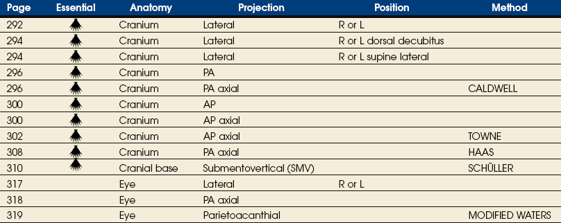
EXPOSURE TECHNIQUE CHART ESSENTIAL PROJECTIONS
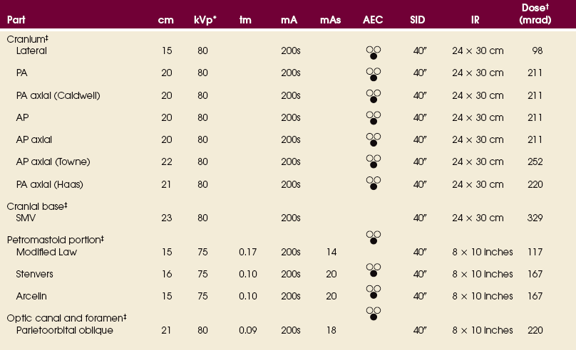
*kVp values are for a three-phase, 12-pulse generator or high frequency.
†Relative doses for comparison use. All doses are skin entrance for average adult at cm indicated.
‡Bucky, 16:1 grid. Screen-film speed 300 or equivalent CR.
See Addendum B for a summary of all abbreviations used in Volume 2.
Skull Topography
The basic localization points and planes of the skull (all of which can be either seen or palpated) used in radiographic positioning are illustrated in Figs. 20-34 and 20-35.
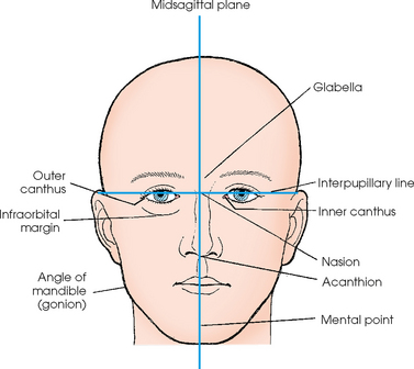
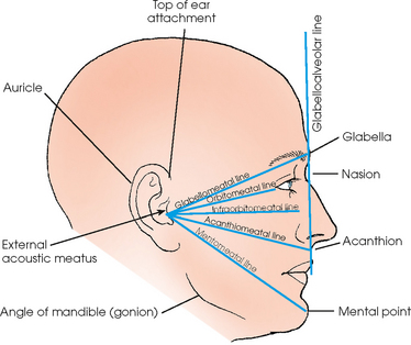
Accurate positioning of the skull requires a full understanding of these landmarks, which should be studied thoroughly before positioning of the skull is learned. The planes, points, lines, and abbreviations most frequently used in skull positioning are as follows:
In an adult, an average 7-degree angle difference exists between the OML and IOML, and an average 8-degree angle difference exists between the OML and the glabellomeatal line. The degree difference between the cranial positioning lines must be recognized. Often the relationship of the patient, IR, and central ray is the same, but the angle that is described may vary depending on the cranial line of reference.
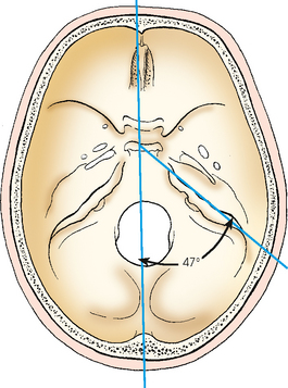
Skull Morphology
Radiographic images of the skull all are based on the normal size and shape of the cranium. Rules have been established for the centering and adjustment of localization points and planes and for the exact degree of central ray angulation for each projection. Although the heads of many patients fall within the limits of normality and can be radiographed satisfactorily using the established positions, numerous skulls vary enough in shape that the standard procedure must be adjusted to obtain an undistorted image.
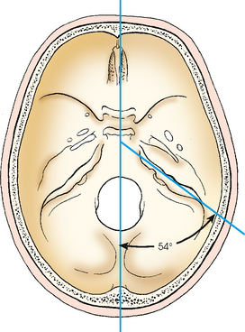
In the typically shaped head (Fig. 20-36), the petrous pyramids project anteriorly and medially at an angle of 47 degrees from the midsagittal plane of the skull. The superior borders of these structures are situated in the base of the cranium.
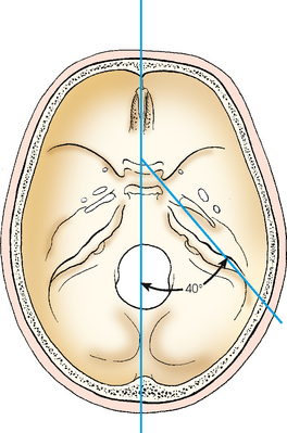
Depending on its shape, the atypical cranium requires more or less rotation of the head or an increase or decrease in the angulation of the central ray compared with the typical, or mesocephalic, skull (see Fig. 20-36). In the brachycephalic skull (Fig. 20-37), which is short from front to back, broad from side to side, and shallow from vertex to base, the internal structures are higher with reference to the IOML, and their long axes are more frontal in position (i.e., the petrous pyramids form a wider angle with the midsagittal plane). The petrous pyramids lie at an average angle of 54 degrees. In the dolichocephalic skull (Fig. 20-38), which is long from front to back, narrow from side to side, and deep from vertex to base, the internal structures are lower with reference to the IOML, and their long axes are less frontal in position (i.e., the petrous pyramids form a narrower angle with the midsagittal plane). The petrous pyramids form an average angle of 40 degrees in the dolichocephalic skull.
Asymmetry must also be considered. The orbits are not always symmetric in size and shape, the lower jaw is often asymmetric, and the nasal bones and cartilage are frequently deviated from the midsagittal plane. Many deviations are not as obvious as these, but if the radiographer adheres to the fundamental rules of positioning, relatively little difficulty is encountered. Varying the position of the part or the degree of central ray angulation to compensate for structural variations becomes a simple procedure if care and precision are used initially.
If possible, the radiography student should obtain a dry skull specimen and radiograph it in the standard positions. This is the best technique for studying the anatomy of the different parts of the cranium from actual and radiographic standpoints. It is important to compare the actual structure (its position in the head, its relationship to adjacent structures in each radiographic position, and its relationship to the IR and the central ray angulation) with the resultant image on the radiograph. In this way, the radiographer can develop the ability to look at a head as though it were transparent—to visualize the location and direction of the internal parts according to the shape of the cranium. By studying the image cast by the part being examined with reference to its relationship to the images of the adjacent structures, the radiographer learns to detect quickly and accurately any error in the image and any deviation from the normal cranium that requires compensation.
It is also advisable to keep a complete set of radiographs of a normally shaped skull. These radiographs can be used for comparison with atypical skulls in determining the deviation and the correct adjustment to make in the degree and direction of part rotation or central ray angulation. Radiographic examples of correct and incorrect skull rotation are shown in Figs. 20-39 and 20-40.
The radiographic positions depicted in Chapters 20 to 22 show the patient either seated at the vertical grid device or lying on a radiographic table. Whether the radiographer elects to perform the examination with the patient in the recumbent or upright position depends on four variables: (1) the equipment available, (2) the age and condition of the patient, (3) the preference of the radiographer and/or radiologist, and (4) whether upright images would increase diagnostic value, such as showing air-fluid levels in paranasal sinuses.
With the exception of paranasal sinuses, which should be radiographed upright, the remaining radiographic positions are shown with the patient either upright or recumbent. Comparable radiographs can usually be obtained with the patient either upright or recumbent. For example, a recumbent skull radiograph can also be obtained with the patient upright as long as the OML and central ray angulation remain constant. Therefore unless specifically noted in the text, the photographic illustration does not constitute a recommendation for performing the examination with the patient in either the upright or recumbent position. Line drawings illustrating both table and upright radiography are included for most radiographic positions in this chapter.
Technical Considerations
The position of the body is important in radiography of the skull. Uncomfortable body position resulting in rotation or other motion is responsible for the majority of repeat examinations. The radiographer, engrossed in adjusting the patient’s head, may forget that the head is attached to a body. If the body is not correctly adjusted, it places so great a strain on the muscles that they cannot support the position. This is especially true when recumbent positions are used for skull radiography. Some guidelines to alleviate strain and facilitate accurate positioning are as follows:
• To prevent lateral rotation of the head, place the patient’s body so that its long axis, depending on the image, either coincides with or is parallel to the midline of the radiographic table. To prevent superior or inferior pull on the head, resulting in longitudinal angulation or tilt, place the patient’s body so that the long axis of the cervical vertebrae coincides with the level of the midpoint of the foramen magnum.
• Support any elevated part, such as the patient’s shoulder or hip, on a pillow or sandbags to relieve strain.
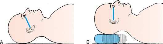
• For examinations of hyposthenic or asthenic patients, elevate the patient’s chest on a small pillow to raise the cervical vertebrae to the correct level for the lateral, PA, and oblique projections when the patient is recumbent.
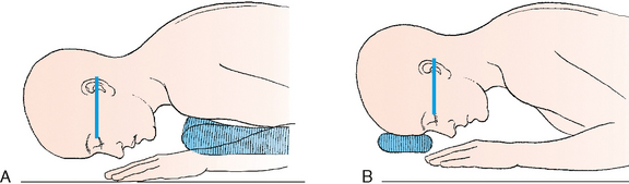
• For examinations of obese or hypersthenic patients, elevate the patient’s head on a radiolucent pad to obtain the correct part-IR relationship if needed. An advantage of a head unit is that it simplifies the handling of these patients.
• While adjusting the body, stand in a position that facilitates estimation of the approximate part position. For example, stand so that the longitudinal axis of the radiographic table is visible as the midsagittal plane of the body is being centered. This allows the anterior surface of the forehead to be viewed while the degree of body rotation for a lateral projection of the skull is adjusted. Therefore the body can be adjusted in such a way that it does not interfere with the final adjustment of the head, and the final position is comfortable for the patient.
When the body is correctly placed and adjusted so that the long axis of the cervical vertebrae is supported at the level of the foramen magnum, the final position of the head requires only minor adjustments. The average patient can maintain this relatively comfortable position without the aid of elaborate immobilization devices, although the following techniques may be helpful:
• If necessary, apply a head clamp with equal pressure on the two sides of the head.
• If such a clamp is not available, use a strip of adhesive tape where it will not be projected onto the image. The portion of the tape touching the hair should have the adhesive side covered with a second piece of tape so that the hairs are not pulled out when the tape is removed. Do not place adhesive tape directly on the patient’s skin.
• When the area to be exposed is small, immobilize the head with sandbags placed against the sides or vertex.
Correct basic body positions and compensatory adjustments for recumbent radiography are illustrated in Figs. 20-41 to 20-48.
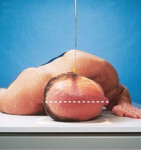
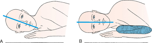
Fig. 20-42 Adjusting sagittal planes to horizontal position. A, Asthenic or hyposthenic patient. B, Angulation corrected.
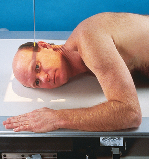
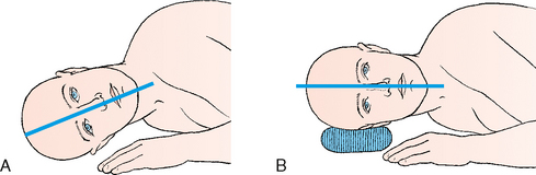
Fig. 20-44 Adjusting sagittal plane to horizontal position. A, Hypersthenic patient. B, Angulation corrected.
CLEANLINESS
The hair and face are naturally oily and leave a residue, even with the most hygienic patients. If the patient is sick, the residue is worse. During positioning of the skull, the patient’s hair, mouth, nose, and eyes come in direct contact with the vertical grid device, tabletop, or IR. For medical asepsis, a paper towel or a cloth sheet may be placed between the imaging surface and the patient. As part of standard procedure, the contacted area should be cleaned with a disinfectant before and after positioning.
Radiation Protection
Protection of the patient from unnecessary radiation is a professional responsibility of the radiographer (see Chapters 1 and 2 for specific guidelines). In this chapter, radiation shielding of the patient is not specified or illustrated. The federal government has reported that placing a lead shield over a patient’s pelvis does not significantly reduce gonadal exposure during imaging of the skull.1 Lead shields should be used to reassure the patient, however.
Infants and children should receive radiation shielding of the thyroid and thymus glands and the gonads. The protective lead shielding used to cover the thyroid and thymus glands can also assist in immobilizing pediatric patients.
The most effective way to protect the patient from unnecessary radiation is to restrict the radiation beam by using proper collimation. Taking care to ensure that the patient is properly instructed and immobilized also reduces the likelihood of having to repeat the procedure, further limiting the radiation exposure received by the patient.
Cranium
R or L position
• With the side of interest closest to the IR, place one hand under the mandibular region and the opposite hand on the upper parietal region of the patient’s head to help guide it into a true lateral position.
• Adjust the patient’s head so that the midsagittal plane is parallel to the plane of the IR. If necessary, place a support under the side of the mandible to prevent it from sagging.
• Adjust the flexion of the patient’s neck so that the IOML is perpendicular to the front edge of the IR. The IOML also should be parallel to the long axis of the IR.
• Check the head position so that the interpupillary line is perpendicular to the IR (Figs. 20-49 to 20-52).
 LATERAL PROJECTION
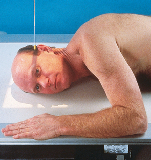
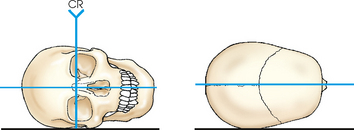
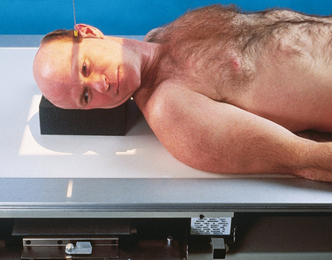
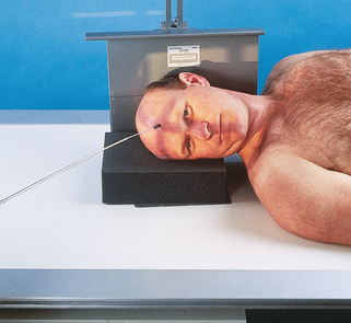
Dorsal decubitus or supine lateral position R or L position
• With the patient supine, adjust the shoulders to lie in the same horizontal plane.
• After ruling out cervical injury, place the side of interest closest to the vertically placed grid IR. Elevate the patient’s head enough to center it to the IR, and then support it on a radiolucent sponge.
• Adjust the patient’s head so that the midsagittal plane is vertical and the interpupillary line is perpendicular to the IR (Fig. 20-53).
• Direct the central ray perpendicular to the IR, and center it 2 inches (5 cm) superior to the EAM.
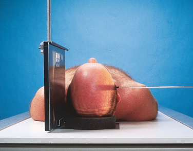
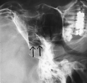
• Robinson et al.1 recommended using the dorsal decubitus lateral projection to show traumatic sphenoid sinus effusion (Fig. 20-54). They stated that this finding may be the only clue to the presence of a basal skull fracture.
• Place the patient in a supine or semisupine position, and turn the head toward the side being examined.
• Elevate and support the opposite shoulder and hip enough that the midsagittal plane of the head is parallel and the interpupillary line is perpendicular to the IR.
• Support the patient’s head with a radiolucent sponge.
• Direct the central ray perpendicular to enter 2 inches (5 cm) superior to the EAM (Fig. 20-55).
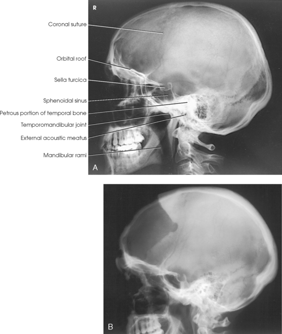
Structures shown: This lateral image of the superimposed halves of the cranium shows the detail of the side adjacent to the IR. The sella turcica, anterior clinoid processes, dorsum sellae, and posterior clinoid processes are well shown in the lateral projection (Fig. 20-56).
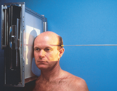
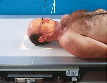
PA AXIAL PROJECTION
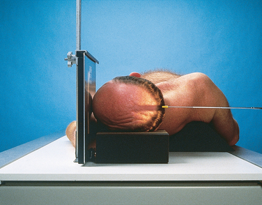
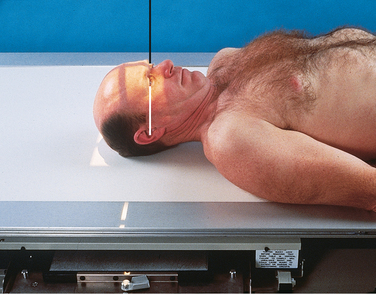
• Adjust the flexion of the patient’s neck so that the OML is perpendicular to the plane of the IR.
• If the patient is recumbent, support the chin on a radiolucent sponge if needed.
• If the patient is obese or hypersthenic, a small radiolucent sponge may need to be placed under (or in front of) the forehead.
• Align the midsagittal plane perpendicular to the IR. This is accomplished by adjusting the lateral margins of the orbits or the EAM equidistant from the tabletop.
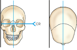
• Immobilize the patient’s head, and center the IR to the nasion (Figs. 20-57 to 20-60).
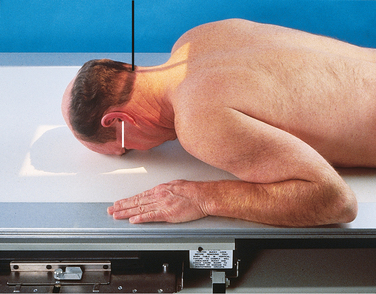
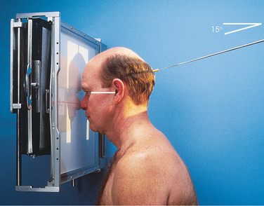
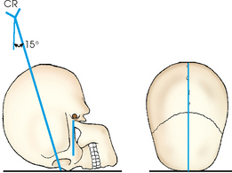
• For the PA projection, when the frontal bone is of primary interest, direct the central ray perpendicular to exit the nasion.
• For the Caldwell method, direct the central ray to exit the nasion at an angle of 15 degrees caudad.
• Center the IR to the central ray.
• To show the superior orbital fissures, direct the central ray through the mid-orbits at an angle of 20 to 25 degrees caudad.
• To show the rotundum foramina, direct the central ray to the nasion at an angle of 25 to 30 degrees caudad. (The Waters method is also used to show the rotundum foramina; see Chapter 22.)
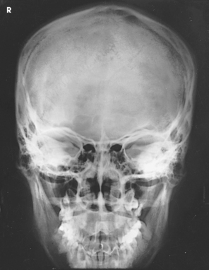
Structures shown: For the PA projection with a perpendicular central ray (Fig. 20-61), the orbits are filled by the margins of the petrous pyramids. Other structures shown include the posterior ethmoidal air cells, crista galli, frontal bone, and frontal sinuses. The dorsum sellae is seen as a curved line extending between the orbits, just above the ethmoidal air cells.
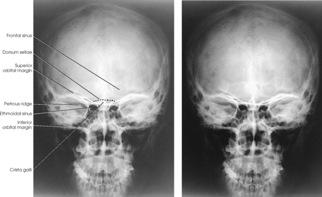
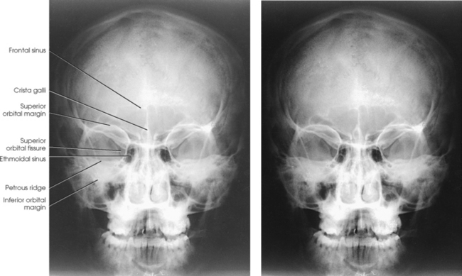
When the central ray is angled 15 degrees caudad to the nasion for the Caldwell method, many of the same structures that appear in the direct PA projection are seen (Fig. 20-62). The petrous ridges are projected into the lower third of the orbits, however. The Caldwell method also shows the anterior ethmoidal air cells. Schüller,1 who first described this positioning for the skull, recommended a caudal angle of 25 degrees.
Stretcher and bedside examinations Lateral decubitus position:
• When the patient cannot be turned to the prone position for the PA Caldwell projection, and cervical spinal injury has been ruled out, elevate one side enough to place the patient’s head in a true lateral position, and support the shoulder and hip on pillows or sandbags if needed.
• Elevate the patient’s head on a suitable support, and adjust its height to center the midsagittal plane of the head to a vertically positioned grid.
• Adjust the patient’s head so that the OML is perpendicular to the plane of the IR (Fig. 20-63).
• Direct the horizontal central ray perpendicular, or 15 degrees caudad, to exit the nasion.
The following should be clearly shown:
 Evidence of proper collimation
Entire cranial perimeter showing three distinct tables of squamous bone
Equal distance from lateral border of skull to lateral border of orbit on both sides
Petrous pyramids lying in lower third of orbit with a caudal central ray angulation of 15 degrees and filling the orbits with 0-degree central ray angulation
Penetration of frontal bone without excessive density at lateral borders of skull
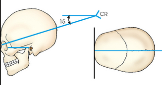
AP AXIAL PROJECTION
When the patient cannot be positioned for a PA or PA axial projection, a similar but magnified image can be obtained with an AP projection.
• Perpendicular (Fig. 20-64) or directed to the nasion at an angle of 15 degrees cephalad (Fig. 20-65)
Structures shown: The structures shown on the AP projection are the same as the structures shown on the PA projection. On the AP projection (Fig. 20-66), the orbits are considerably magnified because of the increased object–to–image receptor distance (OID). Similarly, because of the magnification, the distance from the lateral margin of the orbit to the lateral margin of the temporal bone measures less on the AP projection than on the PA projection.
The following should be clearly shown:
Evidence of proper collimation
Entire cranial perimeter showing three distinct areas of squamous bone
Equal distance from lateral border of skull to lateral border of orbit on both sides
Petrous pyramids lying in lower third of orbit with a cephalad central ray angulation of 15 degrees and filling orbits with a 0-degree central ray angulation
Penetration of frontal bone without excessive density at lateral borders of skull
AP AXIAL PROJECTION
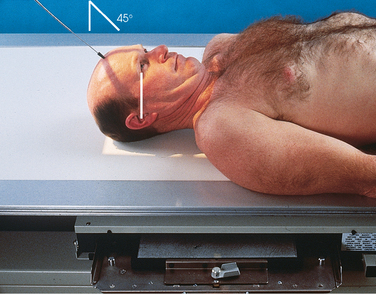
NOTE: Although this technique is most commonly referred to as the Towne method,1 numerous authors have described slightly different variations. In 1912, Grashey2 published the first description of the AP axial projection of the cranium. In 1926, Altschul3 and Towne1 described the position. Altschul recommended strong depression of the chin and direction of the central ray through the foramen magnum at a caudal angle of 40 degrees. Towne (citing Chamberlain) recommended that with the patient’s chin depressed, the central ray should be directed through the midsagittal plane from a point about 3 inches (7.6 cm) above the eyebrows to the foramen magnum. Towne gave no specific central ray angulation, but the angulation would depend on the flexion of the neck.
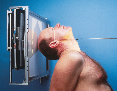
• With the patient either supine or seated upright, center the midsagittal plane of the patient’s body to the midline of the grid.
• Place the patient’s arms in a comfortable position, and adjust the shoulders to lie in the same horizontal plane.
• To ensure the patient’s comfort without increasing the IR distance, examine the hypersthenic or obese patient in the seated-upright position if possible.
• The skull can be brought closer to the IR by having the patient lean back lordotically and rest the shoulders against the vertical grid device. When this is impossible, the desired projection of the occipitobasal region may be obtained by using the PA axial projection described by Haas (pp. 308-309). The Haas method is the reverse of the AP axial projection and produces a comparable result.
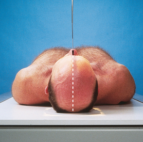
• Adjust the patient’s head so that the midsagittal plane is perpendicular to the midline of the IR.
• Flex the patient’s neck enough to place the OML perpendicular to the plane of the IR.
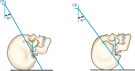
• When the patient cannot flex the neck to this extent, adjust the neck so that the IOML is perpendicular and then increase the central ray angulation by 7 degrees (Figs. 20-67 to 20-70).
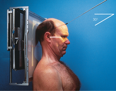
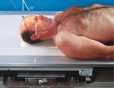
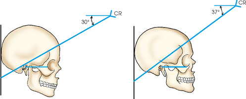
Fig. 20-69 Upright radiography. Same radiographic result with central ray directed 30 degrees to OML or 37 degrees to IOML.
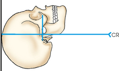
• Position the IR so that its upper margin is at the level of the highest point of the cranial vertex. This places the center at or near the level of the foramen magnum.
• For a localized image of the dorsum sellae and petrous pyramids, adjust the IR so that its midpoint coincides with the central ray. The IR is centered at or slightly below the level of the occlusal plane.
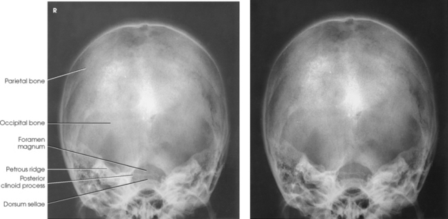
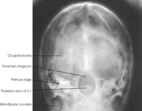
Structures shown: The AP axial projection shows a symmetric image of the petrous pyramids, the posterior portion of the foramen magnum, the dorsum sellae and posterior clinoid processes projected within the foramen magnum, the occipital bone, and the posterior portion of the parietal bones (Fig. 20-71). This projection is also used for tomographic studies of the ears, facial canal, jugular foramina, and rotundum foramina.
The following should be clearly shown:
Evidence of proper collimation
Equal distance from lateral border of skull to lateral margin of foramen magnum on both sides, indicating no rotation
Dorsum sellae and posterior clinoid processes visible within foramen magnum
Penetration of occipital bone without excessive density at lateral borders of skull
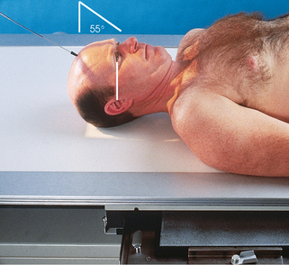
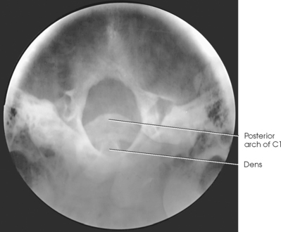
Pathologic condition or trauma: To show the entire foramen magnum, the caudal angulation of the central ray is increased from 40 to 60 degrees to the OML (Figs. 20-72 to 20-76).
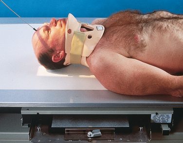
Lateral decubitus position: For pathologic conditions, trauma, or a deformity such as a strongly accentuated dorsal kyphosis when the patient cannot be examined in a direct supine or prone position, the following steps should be taken:
• Adjust and support the body in a semirecumbent position; this allows the head to be placed in a true lateral position.
• Immobilize the IR and grid in a vertical position behind the patient’s occiput.
• Direct the horizontal central ray 30 degrees caudally to the OML (Fig. 20-77).
PA AXIAL PROJECTION
Haas1 devised this projection for obtaining an image of the sellar structures projected within the foramen magnum on hypersthenic, obese, or other patients who cannot be adjusted correctly for the AP axial (Towne) projection.
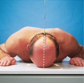
• Rest the patient’s forehead and nose on the table, with the midsagittal plane perpendicular to the midline of the grid.
• Adjust the flexion of the neck so that the OML is perpendicular to the IR (Figs. 20-78 to 20-80).
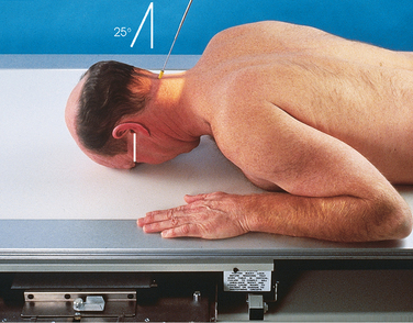
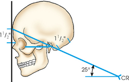
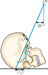
• For a localized image of the sellar region or the petrous pyramids, or both, adjust the position of the IR so that the midpoint coincides with the central ray; shift the IR cephalad approximately 3 inches (7.6 cm) to include the vertex of the skull. An 8- × 10-inch (18- × 24-cm) IR is recommended.
Structures shown: PA axial projection shows the occipital region of the cranium and shows a symmetric image of the petrous pyramids and the dorsum sellae and posterior clinoid processes within the foramen magnum (Figs. 20-81 and 20-82).
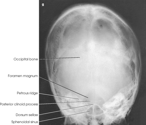
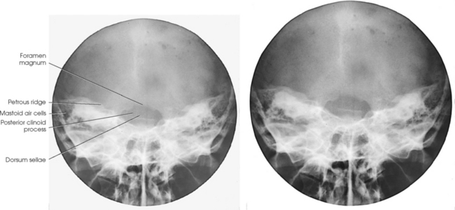
Fig. 20-82 PA axial sella turcica: Haas method, using cylindric extension cone that restricts collimation to small area. Beam restriction decreases scatter radiation and increases visibility of detail of sellar structures.
Cranial Base
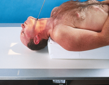
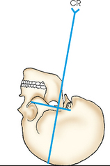
Position of patient: The success of the submentovertical (SMV) projection of the cranial base depends on placing the IOML as nearly parallel with the plane of the IR as possible and directing the central ray perpendicular to the IOML. The following steps are taken:
• Place the patient in the supine or the seated-upright position; the latter is more comfortable. If a chair that supports the back is used, the upright position also allows greater freedom in positioning the patient’s body to place the IOML parallel with the IR. If the patient is seated far enough away from the vertical grid device, the head can usually be adjusted without placing great pressure on the neck.
• When the patient is placed in the supine position, elevate the torso on firm pillows or a suitable pad to allow the head to rest on the vertex with the neck in hyperextension.
• Flex the patient’s knees to relax the abdominal muscles.
• Place the patient’s arms in a comfortable position, and adjust the shoulders to lie in the same horizontal plane.
• Do not keep the patient in the final adjustment longer than is absolutely necessary because the supine position places considerable strain on the neck.
• With the midsagittal plane of the patient’s body centered to the midline of the grid, extend the patient’s neck to the greatest extent as can be achieved, placing the IOML as parallel as possible to the IR.
• Adjust the patient’s head so that the midsagittal plane is perpendicular to the IR (Figs. 20-83 to 20-86).
NOTE: Patients placed in the supine position for the cranial base may have increased intracranial pressure. As a result, they may be dizzy or unstable for a few minutes after having been in this position. Use of the upright position may alleviate some of this pressure.
• Immobilize the patient’s head. In the absence of a head clamp, place a suitably backed strip of adhesive tape across the tip of the chin and anchor it to the sides of the radiographic unit if needed. (The part of the tape touching the skin should be covered.)
• Directed through the sella turcica perpendicular to the IOML. The central ray enters the midsagittal plane of the throat between the angles of the mandible and passes through a point ¾ inch (1.9 cm) anterior to the level of the EAM.
• Center the IR to the central ray. The IR should be parallel to the IOML.
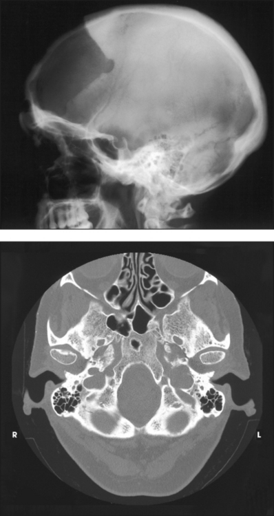
Structures shown: SMV projection of the cranial base shows symmetric images of the petrosae, the mastoid processes, the foramina ovale and spinosum (which are best shown in this projection), the carotid canals, the sphenoidal and ethmoidal sinuses, the mandible, the bony nasal septum, the dens of the axis, and the occipital bone. The maxillary sinuses are superimposed over the mandible (Fig. 20-87).
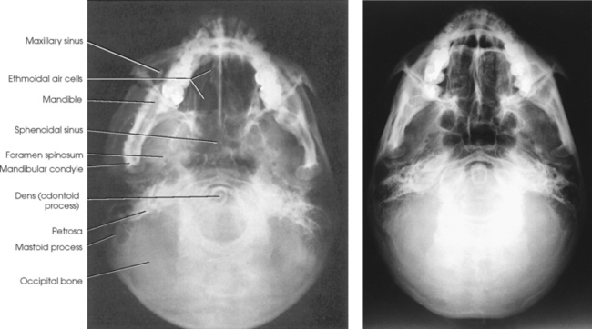
SMV projection is also used for axial tomography of the orbits, optic canals, ethmoid bone, maxillary sinuses, and mastoid processes. With a decrease in the exposure factors, the zygomatic arches are also well shown in this position (see Chapter 22).
The following should be clearly shown:
Evidence of proper collimation
Clearly visible structures of the cranial base, indicated by adequate penetration
Equal distance from lateral border of skull to mandibular condyles on both sides, indicating no tilt
Superimposition of mental protuberance over anterior frontal bone, indicating full extension of neck
Mandibular condyles anterior to petrous pyramids
NOTE: Schüller1 described and illustrated the basal projections—SMV and verticosubmental (VSM)—but Pfeiffer2 gave specific directions for the central ray angulation.
1Schüller A: Die Schädelbasis im Rontgenbild, Fortshr Reontgenstr 11:215, 1905.
2Pfeiffer W: Beitrag zum Wert des axialen Schädelskiagrammes, Arch Laryngol Rhinol 30:1, 1916.
Orbit
The orbits are cone-shaped, bony-walled cavities situated on each side of the midsagittal plane of the head (Fig. 20-88). They are formed by the seven previously described and illustrated bones of the cranium (frontal, ethmoid, and sphenoid) and the face (lacrimal, palatine, maxillary, and zygomatic). Each orbit has a roof, a medial wall, a lateral wall, and a floor. The easily palpable, quadrilateral-shaped anterior circumference of the orbit is called its base. The apex of the orbit corresponds to the optic foramen. The long axis of each orbit is directed obliquely, posteriorly, and medially at an average angle of 37 degrees to the midsagittal plane of the head and superiorly at an angle of about 30 degrees from the OML (Fig. 20-89).
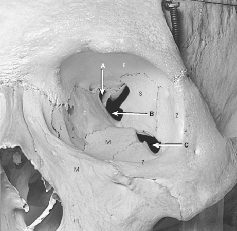
Fig. 20-88 Bones of left orbit of dry specimen. A, Optic canal and foramen. B, Superior orbital fissure. C, Inferior orbital fissure. E, ethmoid; F, frontal; L, lacrimal; M, maxilla; S, sphenoid; Z, zygomatic (palatine not shown).
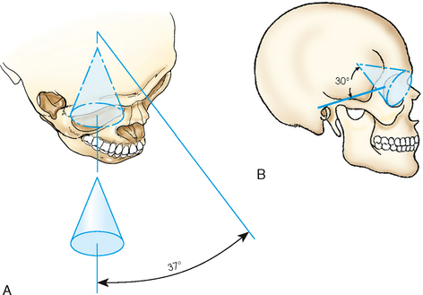
Fig. 20-89 Cone-shaped orbit. A, Average angle of 37 degrees from midsagittal plane. B, Average angle of 30 degrees superior to OML.
The orbits serve primarily as bony sockets for the eyeballs and the structures associated with them, but they also contain blood vessels and nerves that pass through openings in their walls to other regions. The major and frequently radiographed openings are the previously described optic foramina and the superior and inferior orbital sulci.
The superior orbital fissure is the cleft between the greater and lesser wings of the sphenoid bone. From the body of the sphenoid at a point near the orbital apex, this sulcus extends superiorly and laterally between the roof and the lateral wall of the orbit. The inferior orbital fissure is the narrow cleft extending from the lower anterolateral aspect of the sphenoid body anteriorly and laterally between the floor and lateral wall of the orbit. The anterior margin of the cleft is formed by the orbital plate of the maxilla, and its posterior margin is formed by the greater wing of the sphenoid bone and the zygomatic bone.
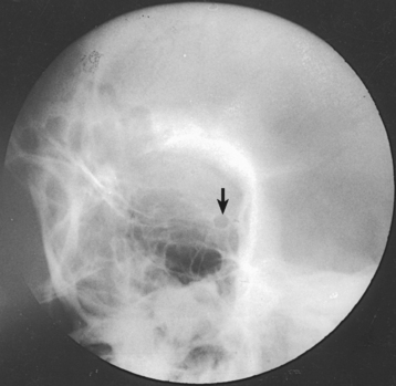
Because the walls of the orbits are thin, they are subject to fracture. When a person is forcibly struck squarely on the eyeball (e.g., by a fist, a piece of sporting equipment), the resulting pressure directed to the eyeball forces the eyeball into the cone-shaped orbit and “blows out” the thin, delicate bony floor of the orbit (Figs. 20-90 and 20-91). The injury must be diagnosed and treated accurately so that the person’s vision is not jeopardized. Blowout fractures may be shown using any combination of radiographs obtained with the patient positioned for parietoacanthial projections (Waters method), radiographic tomography, or computed tomography (CT).
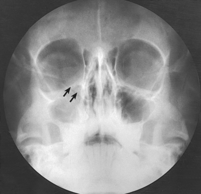
Fig. 20-90 Parietoacanthial orbits using Waters method and showing blowout fracture of orbit (arrows).
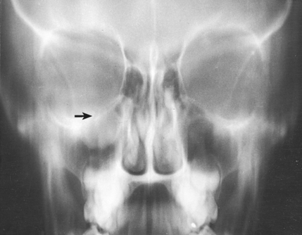
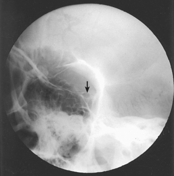
Fig. 20-91 Tomogram: AP projection showing fracture (arrow) in the same patient as in Fig. 20-90.
Eye
The organ of vision, or eye (Latin, oculus; Greek, ophthalmos), consists of the following: eyeball; optic nerve, which connects the eyeball to the brain; blood vessels; and accessory organs such as the extrinsic muscles, lacrimal apparatus, and eyelids (Figs. 20-92 and 20-93).
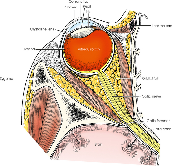
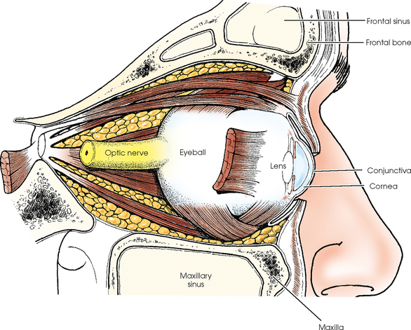
The eyeball is situated in the anterior part of the orbital cavity. Its posterior segment (about two thirds of the bulb) is adjacent to the soft parts that occupy the remainder of the orbital cavity (chiefly muscles, fat, and connective tissue). The anterior portion of the eyeball is exposed and projects beyond the base of the orbit. Bone-free radiographic images of the anterior segment of the eye can be obtained. The exposed part of the eyeball is covered by a thin mucous membrane known as the conjunctiva, portions of which line the eyelids. The conjunctival membrane is kept moist by tear secretions from the lacrimal gland. These secretions prevent drying and friction irritation during movements of the eyeball and eyelids.
The outer, supporting coat of the eyeball is a firm, fibrous membrane consisting of a posterior segment called the sclera and an anterior segment called the cornea. The opaque, white sclera is commonly referred to as the “white of the eye.” The cornea is situated in front of the iris, with its center point corresponding to the pupil. The corneal part of the membrane is transparent, allowing the passage of light into the eyeball, and it serves as one of the four refractive media of the eye.
The inner coat of the eyeball is called the retina. This delicate membrane is contiguous with the optic nerve. The retina is composed chiefly of nervous tissue and several million minute receptor organs, called rods and cones, which transmit light impulses to the brain. The rods and cones are important radiographically because they play a role in the ability of the radiologist or radiographer to see the fluoroscopic image. Their function is described in discussions of fluoroscopy in radiography physics and imaging textbooks.
LOCALIZATION OF FOREIGN BODIES WITHIN ORBIT OR EYE
Ultrasonography and CT (Fig. 20-94) have been increasingly used to locate foreign bodies in the eye. (Magnetic resonance imaging [MRI] is not used for foreign body localization because movement of a metallic foreign object by the magnetic field could lead to hemorrhage or other serious complications.) Whether an ultrasound or a radiographic approach is used, accurate localization of foreign particles lodged within the orbit or eye requires the use of a precision localization technique.
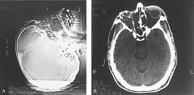
Fig. 20-94 A, Lateral localizer CT image showing multiple buckshot in the face. B, Axial CT image of same patient, showing shotgun pellets within the eye (arrows).
Localization methods removed
The Vogt method, Sweet method, Pfeiffer-Comberg method, and parallax motion method are sometimes used to localize foreign bodies in the eye. These methods were described briefly in the eighth edition of this atlas. Complete descriptions appeared in the seventh and earlier editions.
Image quality
Ultrafine recorded detail is essential to detect and localize minute foreign particles within the orbit or eyeball. The following are required:
1. The geometric unsharpness must be reduced as much as possible by the use of a close OID and a small, undamaged focal spot at a source–to–image receptor distance (SID) that is as long as is consistent with the exposure factors required.
2. Secondary radiation must be minimized by close collimation.
3. Motion must be eliminated by firmly immobilizing the patient’s head and by having the patient gaze steadily at a fixed object, immobilizing the eyeballs.
An artifact can cast an image that simulates the appearance of a foreign body located within the orbit or eye. IRs and screens must be impeccably clean before each examination. In institutions and clinics that often perform these examinations, an adequate number of IR holders are kept in reserve for eye studies only. This measure protects them from the wear of routine use in less critical procedures.
PRELIMINARY EXAMINATION
Lateral projections, PA projections, and bone-free studies are performed to determine whether a radiographically demonstrable foreign body is present. For these radiographs, the patient may be placed in the recumbent position or may be seated upright before a vertical grid device.
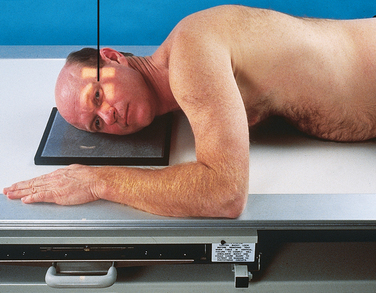
LATERAL PROJECTION
A nongrid (very high-resolution) technique is recommended to reduce magnification and eliminate possible artifacts in or on the radiographic table and grid. The following steps are taken:
• With the patient either semiprone or seated upright, place the outer canthus of the affected eye adjacent to and centered over the midpoint of the IR.
• Adjust the patient’s head to place the midsagittal plane parallel with the plane of the IR and the interpupillary line perpendicular to the IR plane.
• Perpendicular through the outer canthus
• Instruct the patient to look straight ahead for the exposure (Figs. 20-95 and 20-96).
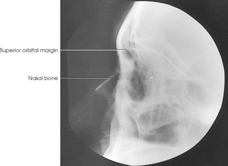
PA AXIAL PROJECTION
A nongrid (very high-resolution) technique is recommended to reduce magnification and eliminate possible artifacts in or on the radiographic table and grid. The following steps are taken:
• Rest the patient’s forehead and nose on the IR holder, and center the holder ¾ inch (1.9 cm) distal to the nasion.
• Adjust the patient’s head so that the midsagittal plane and OML are perpendicular to the plane of the IR.
• Directed through the center of the orbits at a caudal angulation of 30 degrees. This angulation is used to project the petrous portions of the temporal bones below the inferior margin of the orbits (Figs. 20-97 and 20-98).
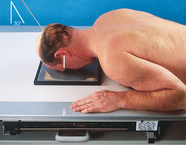
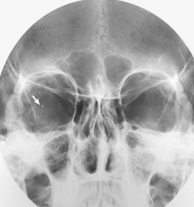
• Instruct the patient to close the eyes and to concentrate on holding them still for the exposure.
PARIETOACANTHIAL PROJECTION
Some physicians prefer to have the PA projection performed with the patient’s head adjusted in a modified Waters position so that the petrous margins are displaced by part adjustment rather than by central ray angulation. The following steps are taken:
• With the IR centered at the level of the center of the orbits, rest the patient’s chin on the IR holder.
• Adjust the patient’s head so that the midsagittal plane is perpendicular to the plane of the IR.
• Adjust the flexion of the patient’s neck so that the OML forms an angle of 50 degrees with the plane of the IR.
• Perpendicular through the mid-orbits (Figs. 20-99 and 20-100)
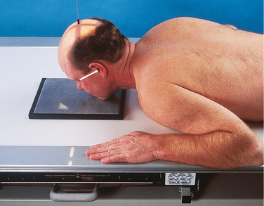
Fig. 20-99 Parietoacanthial projection, modified Waters method, for orbital foreign body localization.
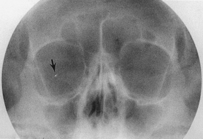
• Instruct the patient to close the eyes and to concentrate on holding them still for the exposure.
1HEW 76-8013 Handbook of Selected Organ Doses.
1Robinson AE et al: Traumatic sphenoid sinus effusion, AJR Am J Roentgenol 101:795, 1967.
1Schüller A: Die Schädelbasis im Rontgenbild, Fortschr Roentgenstr 11:215, 1905.
1Towne EB: Erosion of the petrous bone by acoustic nerve tumor, Arch Otolaryngol 4:515, 1926.
2Grashey R: Atlas typischer Röntgenbilder vom normalen Menschen. In Lehmann’s medizinische Atlanten, ed 2, vol 5, Munich, 1912, JF Lehmann.
3Altschul W: Beiträg zur Röntgenologie des Gehörorganes, Z Hals Nas Ohr 14:335, 1926.
1Scukas J: Contrast media. In Margulis AR, Burhenne HJ, editors: Alimentary tract radiology, vol 1, ed 4, St Louis, 1989, Mosby.
1Haas L: Verfahren zur sagittalen Aufnahme der Sellagegend, Fortschr Roentgenstr 36:1198, 1927.