Mortise Joint1
Medial rotation
Image receptor: 8 × 10 inch (18 × 24 cm) lengthwise or 10 × 12 inch (24 × 30 cm) crosswise for two images on one IR
• Center the patient’s ankle joint to the IR.
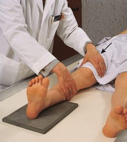
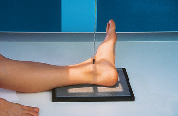
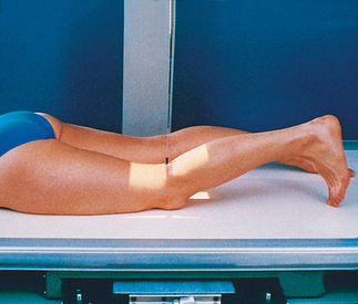
• Grasp the distal femur area with one hand and the foot with the other. Assist the patient by internally rotating the entire leg and foot together 15 to 20 degrees until the intermalleolar plane is parallel with the IR (Fig. 6-100).
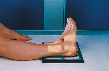
• The plantar surface of the foot should be placed at a right angle to the leg (Fig. 6-101).
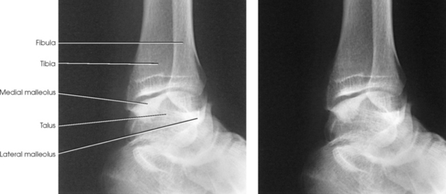
Structures shown: The entire ankle mortise joint should be shown in profile. The three sides of the mortise joint should be visualized (Figs. 6-102 and 6-103).
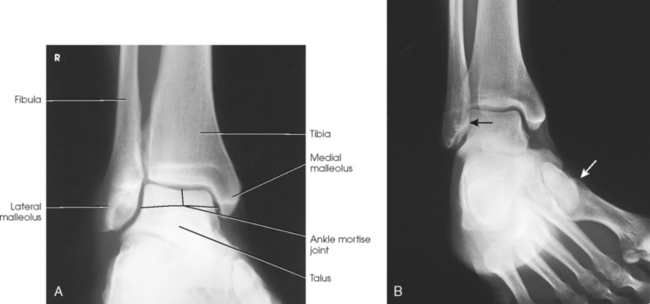
Fig. 6-102 AP oblique ankle, 15- to 20-degree medial rotation to show ankle mortise joint. A, Properly positioned leg to show mortise joint. B, Poorly positioned leg; radiograph had to be repeated. The foot was turned medially (white arrow), but the leg was not. Lateral mortise is closed (black arrow) because the “leg” was not medially rotated.
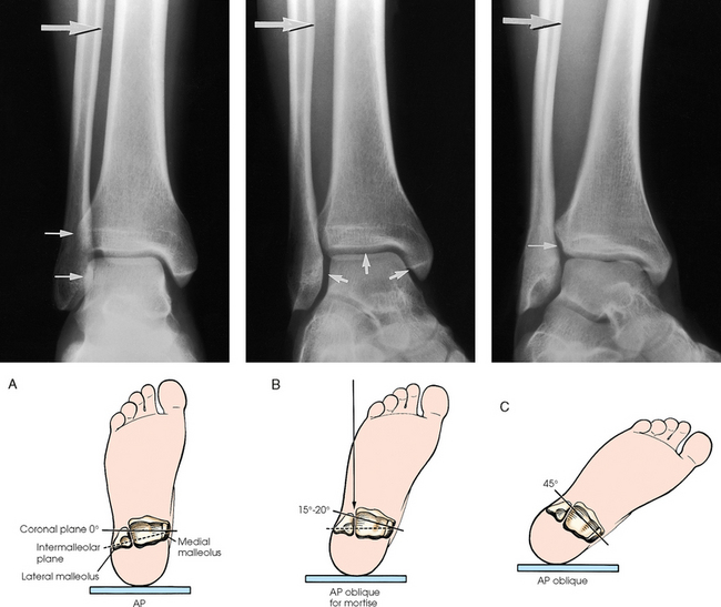
Fig. 6-103 Axial drawing of inferior surface of the tibia and fibula at the ankle joint along with matching radiographs. A, AP ankle position with no rotation of the leg and foot. Drawing shows lateral malleolus positioned posteriorly when leg is in true anatomic position. Radiograph shows normal overlap of anterior tubercle and superolateral talus over fibula (arrows). B, AP oblique ankle, 15- to 20-degree medial rotation to show ankle mortise. Drawing shows both malleoli parallel with IR. Radiograph clearly shows all three aspects of mortise joint (arrows). C, AP oblique ankle, 45-degree medial rotation. Radiograph shows tibiofibular joint (arrow) and entire distal fibula in profile. Larger upper arrow show wider space created between tibia and fibula as leg is turned medially for two AP oblique projections. This space should be observed when ankle radiographs are checked for proper positioning.
AP OBLIQUE PROJECTION
• Place the plantar surface of the patient’s foot in the vertical position, and laterally rotate the leg and foot 45 degrees.
• Rest the foot against a foam wedge for support, and center the ankle joint to the IR (Fig. 6-104).
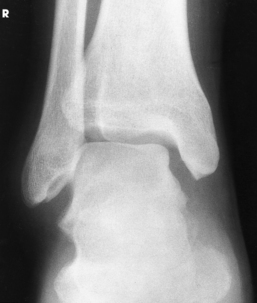
Structures shown: The lateral rotation oblique projection is useful in determining fractures and showing the superior aspect of the calcaneus (Fig. 6-105).
 AP PROJECTION
Stress studies of the ankle joint usually are obtained after an inversion or eversion injury to verify the presence of a ligamentous tear. Rupture of a ligament is shown by widening of the joint space on the side of the injury when, without moving or rotating the lower leg from the supine position, the foot is forcibly turned toward the opposite side.
When the injury is recent and the ankle is acutely sensitive to movement, the orthopedic surgeon may inject a local anesthetic into the sinus tarsi preceding the examination. The physician adjusts the foot when it must be turned into extreme stress and holds or straps it in position for the exposure. The patient usually can hold the foot in the stress position when the injury is not too painful or after he or she has received a local anesthetic by asymmetrically pulling on a strip of bandage looped around the ball of the foot (Figs. 6-106 to 6-108).
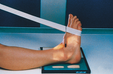
Fig. 6-106 AP ankle in neutral position. Use of lead glove and stress of the joint is required to obtain inversion and eversion radiographs (see Fig. 6-108).

AP PROJECTION
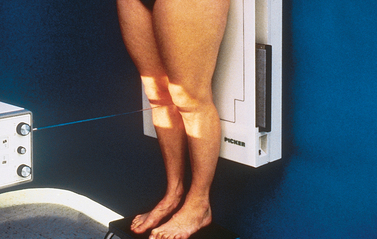
Standing
This projection is performed to identify ankle joint space narrowing with weight-bearing.
• Place the patient in the upright position, preferably on a low platform that has a cassette groove. If such a platform is unavailable, use blocks to elevate the feet to the level of the x-ray tube (Fig. 6-109).
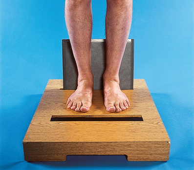
• Ensure that the patient has proper support. Never stand the patient on the radiographic table.
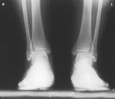
Structures shown: The resulting image shows an AP projection of both ankle joints and the relationship of the distal tibia and fibula with weight-bearing. It also shows side-to-side comparison of the joint (Fig. 6-110).
Leg
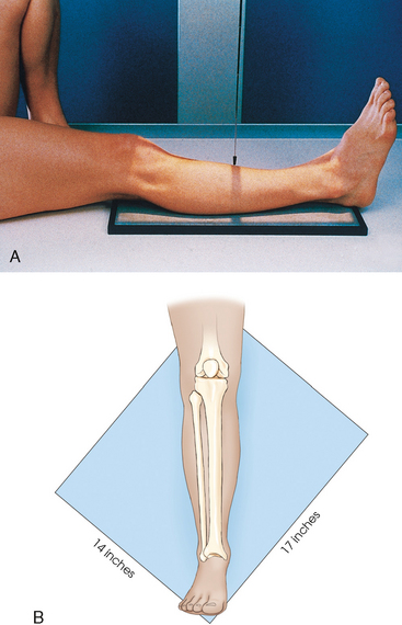
For this projection and the lateral and oblique projections described in the following sections, the long axis of the IR is placed parallel with the long axis of the leg and centered to the midshaft. Unless the leg is unusually long, the IR extends beyond the knee and ankle joints enough to prevent their being projected off the IR by the divergence of the x-ray beam. The IR must extend 1 to 1½ inches (2.5 to 3.8 cm) beyond the joints. When the leg is too long for these allowances, and the site of the lesion is unknown, two images should always be made. In these instances, the leg is imaged with the ankle joint, and a separate knee projection is performed. Diagonal use of a 14 × 17 inch (35 × 43 cm) IR is also an option if the leg is too long to fit lengthwise and if such use is permitted by the facility. The use of a 48-inch (122-cm) SID reduces the divergence of the x-ray beam, and more of the body part is included.
• Adjust the patient’s body so that the pelvis is not rotated.
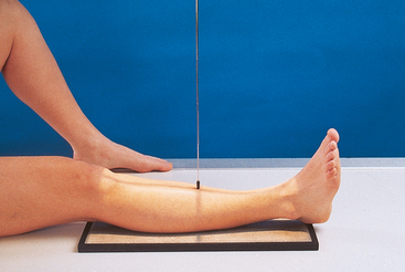
• Adjust the leg so that the femoral condyles are parallel with the IR and the foot is vertical.
• Flex the ankle until the foot is in the vertical position.
• If necessary, place a sandbag against the plantar surface of the foot to immobilize it in the correct position (Fig. 6-111).
Structures shown: The resulting image shows the tibia, fibula, and adjacent joints (Fig. 6-112).
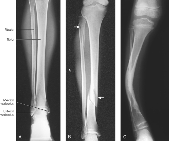
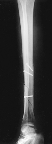
Fig. 6-112 A, AP tibia and fibula. Long leg length prevented showing entire leg. A separate knee projection had to be performed on this patient. B, Short leg length allowed entire leg to be shown. Spiral fracture of distal tibia with accompanying spiral fracture of proximal fibula (arrows) is seen. This radiograph shows the importance of including the entire length of a long bone in trauma cases. C, AP tibia and fibula on a 4-year-old with neurofibromatosis.
LATERAL PROJECTION
• Turn the patient toward the affected side with the leg on the IR.
• Adjust the rotation of the body to place the patella perpendicular to the IR, and ensure that a line drawn through the femoral condyles is also perpendicular.
• Place sandbag supports where needed for the patient’s comfort and to stabilize the body position (Fig. 6-113, A).
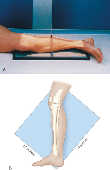
Fig. 6-113 A, Lateral tibia and fibula. B, Projection done on a 14 × 17 inch (35 × 43 cm) IR diagonal to include knee and ankle joint.
• The knee may be flexed if necessary to ensure a true lateral position.
• The projection may be done with IR diagonal to include the ankle and knee joints (Fig. 6-113, B). Similar to the AP, if the leg is too long, it is imaged with the ankle joint, and a separate knee projection is performed.
• When the patient cannot be turned from the supine position, the lateromedial lateral projection may be taken cross-table using a horizontal central ray.
• Lift the leg enough for an assistant to slide a rigid support under the patient’s leg.
• The IR may be placed between the legs, and the central ray may be directed from the lateral side.
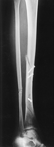
Structures shown: The resulting image shows the tibia, fibula, and adjacent joints (Fig. 6-114).
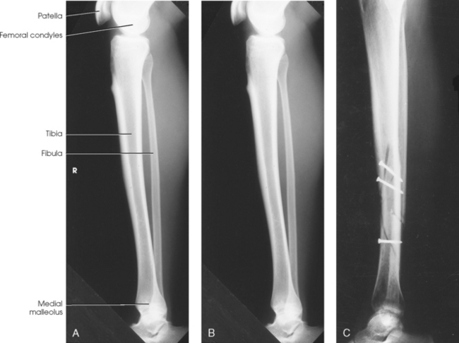
Fig. 6-114 A and B, Lateral tibia and fibula. C, Lateral postreduction tibia and fibula showing fixation device. The leg was too long to fit on one image.
The following should be clearly shown:
 Evidence of proper collimation
Ankle and knee joints on one or more images
Distal fibula lying over the posterior half of the tibia
Slight overlap of the tibia on the proximal fibular head
Ankle and knee joints not rotated
Possibly no superimposition of femoral condyles because of divergence of the beam
Moderate separation of the tibial and fibular bodies or shafts (except at their articular ends)
AP OBLIQUE PROJECTIONS
• Perform oblique projections of the leg by alternately rotating the limb 45 degrees medially (Fig. 6-115) or laterally (Fig. 6-116). For the medial rotation, ensure that the leg is turned inward and not just the foot.

• For the medial oblique projection, elevate the affected hip enough to rest the medial side of the foot and ankle against a 45-degree foam wedge, and place a support under the greater trochanter.
Structures shown: The resulting image shows a 45-degree oblique projection of the bones and soft tissues of the leg and one or both of the adjacent joints (Figs. 6-117 and 6-118).
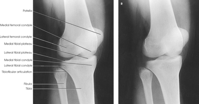
Knee
Radiographs of the knee may be taken with or without use of a grid. The factors to consider in reaching a decision are the size of the patient’s knee and the preference of the radiographer and physician.
Gonad shielding is needed during examinations of the lower limbs. (Lead shielding is not shown on illustrations of the patient model because it would obstruct demonstration of the body position.)
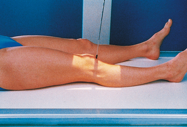
• With the IR under the patient’s knee, flex the joint slightly, locate the apex of the patella, and as the patient extends the knee, center the IR about ½ inch (1.3 cm) below the patellar apex. This centers the IR to the joint space.
• Adjust the patient’s leg by placing the femoral epicondyles parallel with the IR for a true AP projection (Fig. 6-119). The patella lies slightly off center to the medial side. If the knee cannot be fully extended, a curved IR may be used.
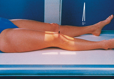
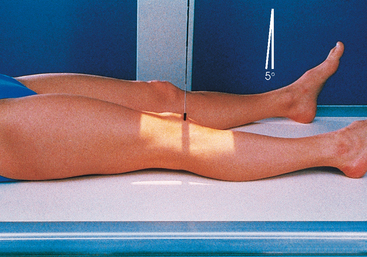
• Directed to a point ½ inch (1.3 cm) inferior to the patellar apex
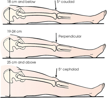
• Variable, depending on the measurement between the anterior superior iliac spine (ASIS) and the tabletop (Fig. 6-120), as follows1:
| < 19 cm | 3-5 degrees caudad (thin pelvis) |
| 19-24 cm | 0 degrees |
| > 24 cm | 3-5 degrees cephalad (large pelvis) |
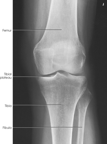
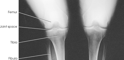
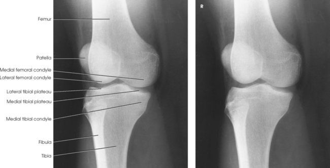
Structures shown: The resulting image shows an AP projection of the knee structures (Fig. 6-121).
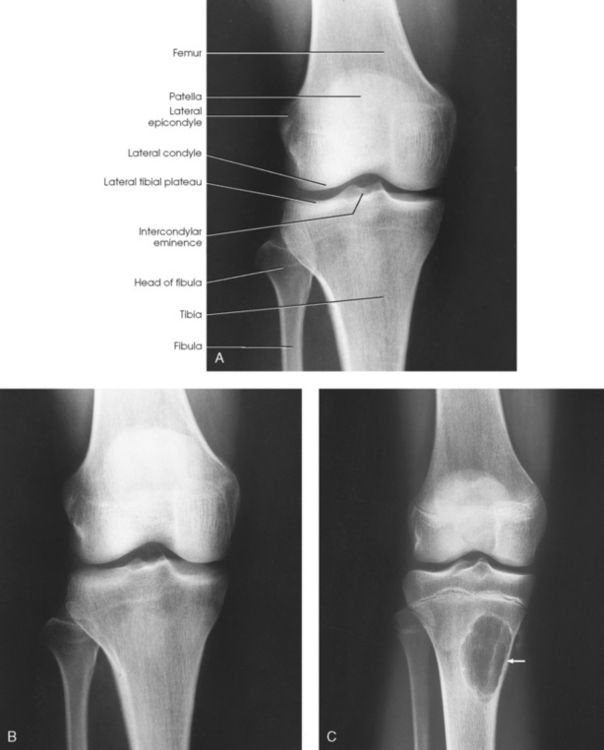
Fig. 6-121 A, AP knee with central ray (CR) angled 5 degrees cephalad. Patient’s ASIS-to-tabletop distance was greater than 25 cm. B, Same patient as in A with CR perpendicular. Note joint space is not opened as well. C, AP knee on a 15-year-old. Arrow is pointing to a benign lesion in the tibia.
The following should be clearly shown:
Evidence of proper collimation
Open femorotibial joint space, with interspaces of equal width on both sides if the knee is normal
Knee fully extended if patient’s condition permits
Patella completely superimposed on the femur
No rotation of the femur (femoral condyles symmetric) and tibia (intercondylar eminence centered)
Slight superimposition of the fibular head if the tibia is normal
PA PROJECTION
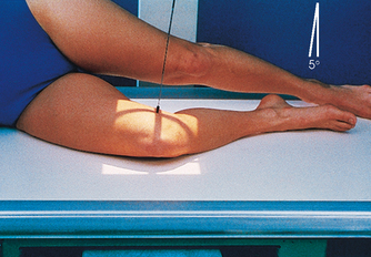
• Center a point ½ inch (1.3 cm) below the patellar apex to the center of the IR, and adjust the patient’s leg so that the femoral epicondyles are parallel with the tabletop. Because the knee is balanced on the medial side of the obliquely located patella, care must be used in adjusting the knee (Fig. 6-122).
• Directed at an angle of 5 to 7 degrees caudad to exit a point ½ inch (1.3 cm) inferior to the patellar apex. Because the tibia and fibula are slightly inclined, the central ray is parallel with the tibial plateau. A perpendicular CR may be needed for patients with large thighs or when the foot is dorsiflexed.
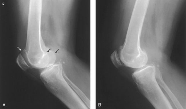
Structures shown: The resulting image shows a PA projection of the knee (Fig. 6-123).
LATERAL PROJECTION
• Ask the patient to turn onto the affected side. Ensure that the pelvis is not rotated.
• For a standard lateral projection, have the patient bring the affected knee forward and extend the other limb behind it (Fig. 6-124). The other limb may also be placed in front of the affected knee on a support block.
• Flexion of 20 to 30 degrees is usually preferred because this position relaxes the muscles and shows the maximum volume of the joint cavity.1
• To prevent fragment separation in new or unhealed patellar fractures, the knee should not be flexed more than 10 degrees.
• Place a support under the ankle.
• Grasp the epicondyles and adjust them so that they are perpendicular to the IR (condyles superimposed). The patella is perpendicular to the plane of the IR (Fig. 6-125).
• Directed to the knee joint 1 inch (2.5 cm) distal to the medial epicondyle at an angle of 5 to 7 degrees cephalad. This slight angulation of the central ray prevents the joint space from being obscured by the magnified image of the medial femoral condyle. In addition, in the lateral recumbent position, the medial condyle is slightly inferior to the lateral condyle.
Structures shown: The resulting radiograph shows a lateral image of the distal end of the femur, patella, knee joint, proximal ends of the tibia and fibula, and adjacent soft tissue (Fig. 6-126).
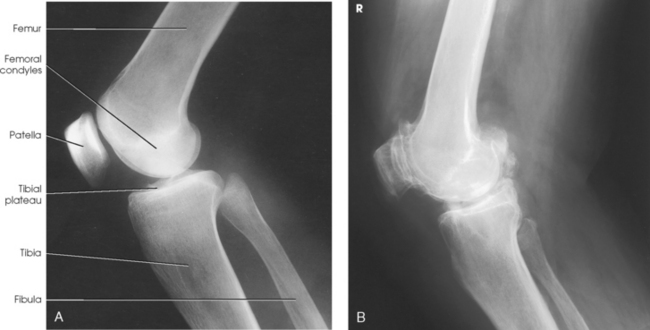
The following should be clearly shown:
Evidence of proper collimation
Femoral condyles superimposed (locate the adductor tubercle on the posterior surface of the medial condyle to identify the medial condyle and to determine whether the knee is overrotated or underrotated)
Open joint space between femoral condyles and tibia
Open patellofemoral joint space
Fibular head and tibia slightly superimposed (overrotation causes less superimposition, and underrotation causes more superimposition)
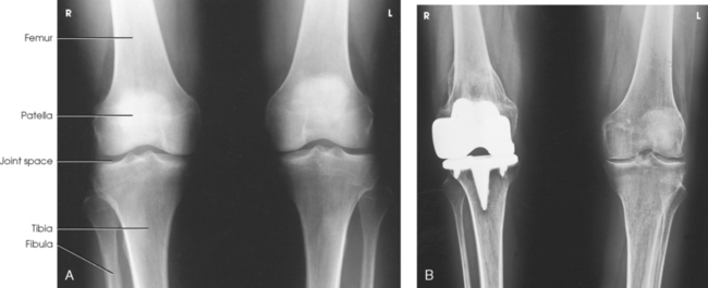
Knees
Standing
Leach et al.1 recommended that a bilateral weight-bearing AP projection be routinely included in radiographic examination of arthritic knees. They found that a weight-bearing study often reveals narrowing of a joint space that appears normal on a non–weight-bearing study.
• Adjust the patient’s position to center the knees to the IR.
• Place the toes straight ahead, with the feet separated enough for good balance.
• Ask the patient to stand straight with knees fully extended and weight equally distributed on the feet.
• Center the IR ½ inch (1.3 cm) below the apices of the patellae (Fig. 6-127).
Structures shown: The resulting image shows the joint spaces of the knees. Varus and valgus deformities can also be evaluated with this procedure (Fig. 6-128).
PA PROJECTION
ROSENBERG METHOD1
Standing flexion
• For a direct PA projection, have the patient stand upright with the knees in contact with the vertical grid device.
• Center the IR at a level ½ inch (1.3 cm) below the apices of the patellae.
• Have the patient grasp the edges of the grid device and flex the knees to place the femora at an angle of 45 degrees (Fig. 6-129).
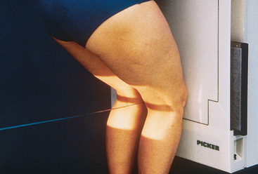
Structures shown: The PA weight-bearing method is useful for evaluating joint space narrowing and showing articular cartilage disease (Fig. 6-130). The image is similar to images obtained when radiographing the intercondylar fossa.
Knee
Lateral rotation
• If necessary, elevate the hip of the unaffected side enough to rotate the affected limb.
• Support the elevated hip and knee of the unaffected side (Fig. 6-131).
• Center the IR ½ inch (1.3 cm) below the apex of the patella.
Structures shown: The resulting image shows an AP oblique projection of the laterally rotated femoral condyles, patella, tibial condyles, and head of the fibula (Fig. 6-132).
AP OBLIQUE PROJECTION
• Medially rotate the limb, and elevate the hip of the affected side enough to rotate the limb 45 degrees.
• Place a support under the hip, if needed (Fig. 6-133).
Structures shown: The resulting image shows an AP oblique projection of the medially rotated femoral condyles, patella, tibial condyles, proximal tibiofibular joint, and head of the fibula (Fig. 6-134).
Intercondylar Fossa
The PA axial, or tunnel, projection, first described by Holmblad1 in 1937, required that the patient assume a kneeling position on the radiographic table. In 1983, the Holmblad method2 was modified so that if the patient’s condition allowed, a standing position could be used.
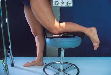
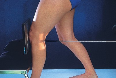
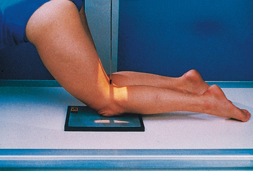
• After consideration of the patient’s safety, place the patient in one of three positions: (1) standing with the knee of interest flexed and resting on a stool at the side of the radiographic table (Fig. 6-135); (2) standing at the side of the radiographic table with the affected knee flexed and placed in contact with the front of the IR (Fig. 6-136); or (3) kneeling on the radiographic table as originally described by Holmblad, with the affected knee over the IR (Fig. 6-137). In all three approaches, the patient leans on the radiographic table for support.
• For all positions, place the IR against the anterior surface of the patient’s knee, and center the IR to the apex of the patella. Flex the knee 70 degrees from full extension (20-degree difference from the central ray, as shown in Fig. 6-138).
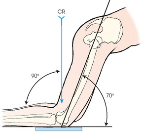
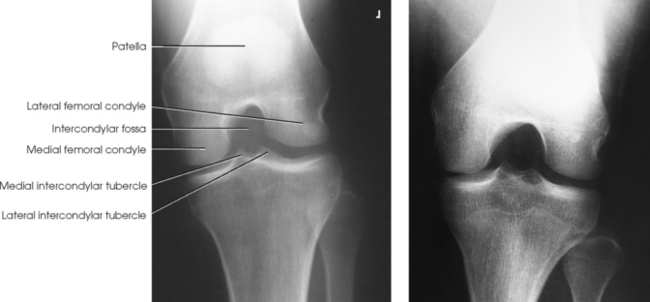
Structures shown: The image shows the intercondylar fossa of the femur and the medial and lateral intercondylar tubercles of the intercondylar eminence in profile (Fig. 6-139). Holmblad1 stated that the degree of flexion used in this position widens the joint space between the femur and tibia and gives an improved image of the joint and the surfaces of the tibia and femur.
The following should be clearly shown:
Evidence of proper collimation
Posteroinferior surface of the femoral condyles
Intercondylar eminence and knee joint space
Apex of the patella not superimposing the fossa
No rotation, evident by slight tibiofibular overlap
Soft tissue in the fossa and interspaces
Bony detail on the intercondylar eminence, distal femur, and proximal tibia
NOTE: The bilateral examination (Rosenberg method) is described on p. 303 (also see Fig. 6-130).
PA AXIAL PROJECTION
CAMP-COVENTRY METHOD1
• Flex the patient’s knee to a 40- or 50-degree angle, and rest the foot on a suitable support.
• Center the upper half of the IR to the knee joint; the central ray angulation projects the joint to the center of the IR (Figs. 6-140 and 6-141).
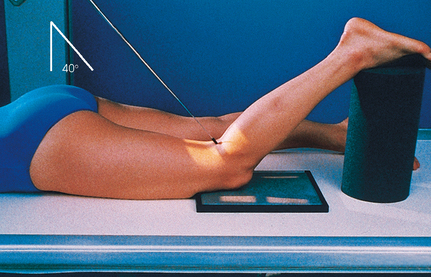
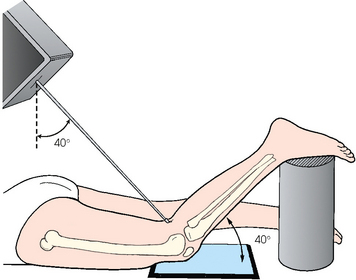
• A protractor may be used beside the leg to determine the correct leg angle.
• Adjust the leg so that the knee has no medial or lateral rotation.
Structures shown: This axial image shows an unobstructed projection of the intercondyloid fossa and the medial and lateral intercondylar tubercles of the intercondylar eminence (Figs. 6-142 and 6-143).
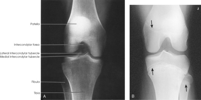
Fig. 6-142 Camp-Coventry method. A, Flexion of knee at 40 degrees. B, Flexion of knee at 40 degrees in a 13-year-old patient. Note epiphyses (arrows).
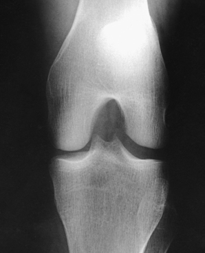
Fig. 6-143 Flexion of knee at 50 degrees (same patient as in Fig. 6-142): Camp-Coventry method.
The following should be clearly shown:
Evidence of proper collimation
Posteroinferior surface of the femoral condyles
Intercondylar eminence centered in open femorotibial joint space
Apex of the patella not superimposing the fossa
No rotation, evident by slight tibiofibular overlap
Soft tissue in the fossa and interspaces
Bony detail on the intercondylar eminence, distal femur, and proximal tibia
NOTE: In routine examinations of the knee joint, an intercondylar fossa projection is usually included to detect loose bodies (“joint mice”). This projection is also used in evaluating split and displaced cartilage in osteochondritis dissecans and flattening, or underdevelopment, of the lateral femoral condyle in congenital slipped patella.
AP AXIAL PROJECTION
• Flex the affected knee enough to place the long axis of the femur at an angle of 60 degrees to the long axis of the tibia.
• Support the knee on sandbags (Fig. 6-144).
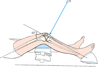
• Place the IR under the knee, and position the IR so that the center point coincides with the central ray.
• Adjust the leg so that the femoral condyles are equidistant from the IR. Immobilize the foot with sandbags.
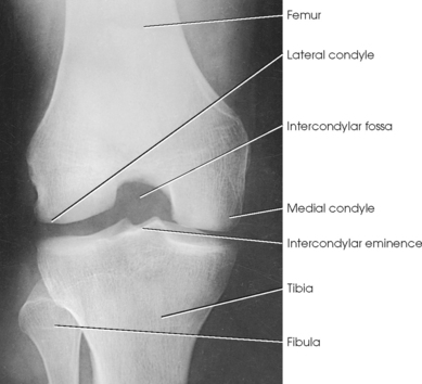
Structures shown: The resulting image shows the intercondylar fossa, intercondylar eminence, and knee joint (Fig. 6-145).
The following should be clearly shown:
Posteroinferior surface of the femoral condyles
Intercondylar eminence and knee joint space
No superimposition of the fossa by the apex of the patella
No rotation, evident by slight tibiofibular overlap
Soft tissue in the fossa and interspaces
Bony detail on the intercondylar eminence, distal femur, and proximal tibia
Patella
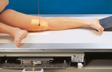
• Center the IR to the patella.
• Adjust the position of the leg to place the patella parallel with the plane of the IR. This usually requires that the heel be rotated 5 to 10 degrees laterally (Fig. 6-146).
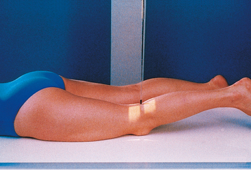
Structures shown: The PA projection of the patella provides sharper recorded detail than in the AP projection because of a closer object-to-IR distance (OID) (Figs. 6-147 and 6-148).
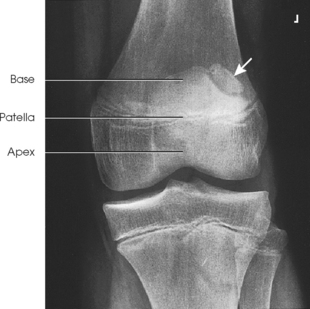
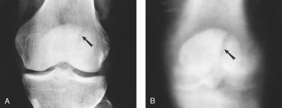
Fig. 6-148 A, Conventional PA projection of patella shows vertical radiolucent line (arrow) passing through junction of lateral and middle third of patella. B, On tomography this defect extends from superior to inferior margin of patella. It is a bipartite patella and not a fracture.
LATERAL PROJECTION
• Ask the patient to turn onto the affected hip. A sandbag may be placed under the ankle for support.
• Have the patient flex the unaffected knee and hip, and place the unaffected foot in front of the affected limb for stability.
• Flex the affected knee approximately 5 to 10 degrees. Increasing the flexion reduces the patellofemoral joint space.
• Adjust the knee in the lateral position so that the femoral epicondyles are superimposed, and the patella is perpendicular to the IR (Fig. 6-149).
Structures shown: The resulting image shows a lateral projection of the patella and patellofemoral joint space (Figs. 6-150 and 6-151).

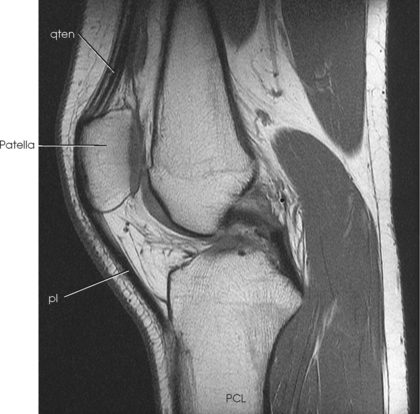
Fig. 6-151 Sagittal MRI shows patella, patellofemoral joint and surrounding soft tissues. Quadriceps tendon (qten) and patellar ligament (pl) are shown on this image.
Patella and Patellofemoral Joint
Radiography of the patella has been the topic of hundreds of articles. For a tangential radiograph, the patient may be placed in any of the following body positions: prone, supine, lying on the side, seated on the table, seated on the radiographic table with the leg hanging over the edge, or standing.
Various authors have described the degree of flexion of the knee joint as ranging from 20 to 120 degrees. Laurin3 reported that patellar subluxation is easier to show when the knee is flexed 20 degrees and noted a limitation of using this small angle. Modern radiographic equipment often does not permit such small angles because of the large size of the collimator.
Fodor et al.4 and Merchant et al.5 recommended a 45-degree flexion of the knee, and Hughston6 recommended an approximately 55-degree angle with the central ray angled 45 degrees. In addition, Merchant et al.5 stated that relaxation of the quadriceps muscles is required to show patellar subluxation.
Image receptor: 8 × 10 inch (18 × 24 cm) for unilateral examination; 10 × 12 inch (24 × 30 cm) crosswise for bilateral examination
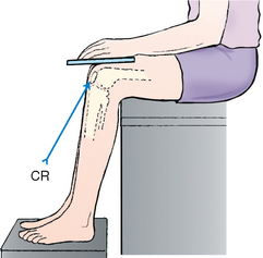
• Place the IR under the patient’s knee, and slowly flex the affected knee so that the tibia and fibula form a 50- to 60-degree angle from the table.
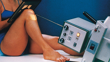
• Rest the foot against the collimator, or support it in position (Fig. 6-152).
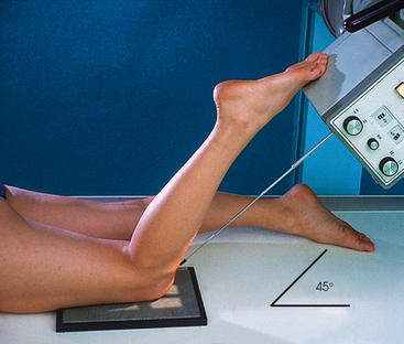
• Ensure that the collimator surface is not hot because this could burn the patient.
• Adjust the patient’s leg so that it is not rotated medially or laterally from the vertical plane.
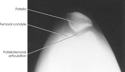
Structures shown: The tangential image shows subluxation of the patella and patellar fractures and allows radiologic assessment of the femoral condyles. Hughston recommended that both knees be examined for comparison (Fig. 6-153).
TANGENTIAL PROJECTION
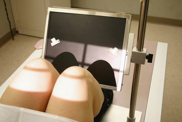
MERCHANT METHOD1
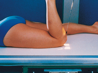
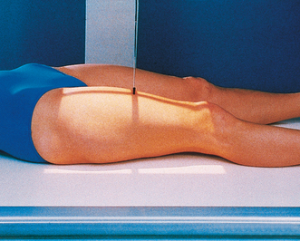
• Place the patient supine with both knees at the end of the radiographic table.
• Support the knees and lower legs with an adjustable IR-holding device (Axial Viewer).2
• To increase comfort and relaxation of the quadriceps femoris, place pillows or a foam wedge under the patient’s head and back.
• Using the Axial Viewer device, elevate the patient’s knees approximately 2 inches to place the femora parallel with the tabletop (Figs. 6-154 and 6-155).
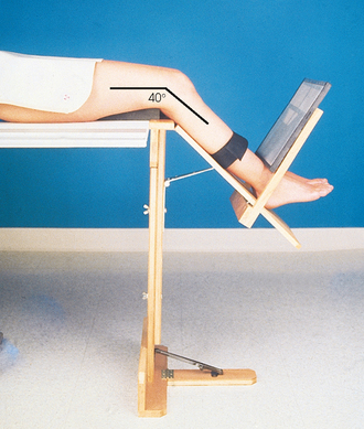
Fig. 6-154 Tangential patella and patellofemoral joint: Merchant method. Note use of Axial Viewer device.
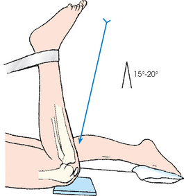
• Adjust the angle of knee flexion to 40 degrees. (Merchant reported that the degree of angulation may be varied between 30 degrees and 90 degrees to show various patellofemoral disorders.)
• Strap both legs together at the calf level to control leg rotation and allow patient relaxation.
• Place the IR perpendicular to the central ray and resting on the patient’s shins (a thin foam pad aids comfort) approximately 1 ft distal to the patellae.
• Ensure that the patient is able to relax. Relaxation of the quadriceps femoris is crucial for an accurate diagnosis. If these muscles are not relaxed, a subluxated patella may be pulled back into the intercondylar sulcus, showing a false normal appearance.
• Record the angle of knee flexion for reproducibility during follow-up examinations because the severity of patella subluxation commonly changes inversely with the angle of knee flexion.
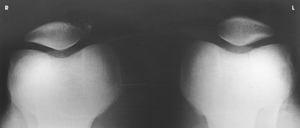
Structures shown: The bilateral tangential image shows an axial projection of the patellae and patellofemoral joints (Fig. 6-156). Because of the right-angle alignment of the IR and central ray, the patellae are seen as nondistorted, albeit slightly magnified, images.
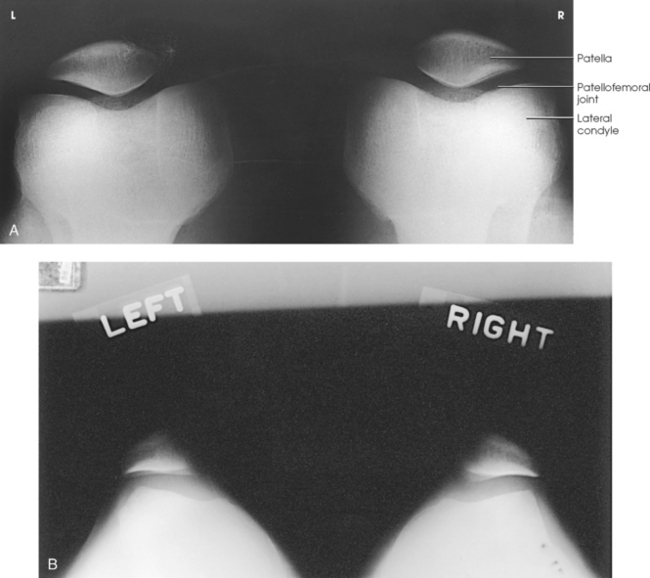
Fig. 6-156 A, Normal tangential radiograph of congruent patellofemoral joints, showing patellae to be well centered with normal trabecular pattern. B, Abnormal tangential radiograph showing abnormally shallow intercondylar sulci, misshapen and laterally subluxated patellae, and incongruent patellofemoral joints (left worse than right). (Courtesy Alan J. Merchant.)
TANGENTIAL PROJECTION
Because of the danger of fragment displacement by the acute knee flexion required for this procedure, this projection should not be attempted until a transverse fracture of the patella has been ruled out with a lateral image, or if the patient is in pain.
• Place the patient in the supine or prone position. The latter is preferable because the knee can usually be flexed to a greater degree, and immobilization is easier (Figs. 6-157 and 6-158).
• If the patient is seated on the radiographic table, hold the IR securely in place (Fig. 6-159). Alternative positions are shown in Figs. 6-160 and 6-161.
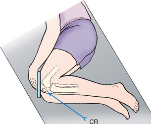
• Flex the patient’s knee slowly as much as possible or until the patella is perpendicular to the IR if the patient’s condition permits. With slow, even flexion, the patient should be able to tolerate the position, whereas quick, uneven flexion may cause too much pain.
• If desired, loop a long strip of bandage around the patient’s ankle or foot. Have the patient grasp the ends over the shoulder to hold the leg in position. Gently adjust the leg so that its long axis is vertical.
• Place the IR transversely under the knee, and center it to the joint space between the patella and the femoral condyles.
• By maintaining the same OID and SID relationships, this position can be obtained with the patient in a lateral or seated position (see Figs. 6-160 and 6-161).
NOTE: When the central ray is directed toward the patient’s upper body (see Figs. 6-159 and 6-160), the thorax and thyroid should be shielded. Gonad shielding (not shown) should be used in all patients.
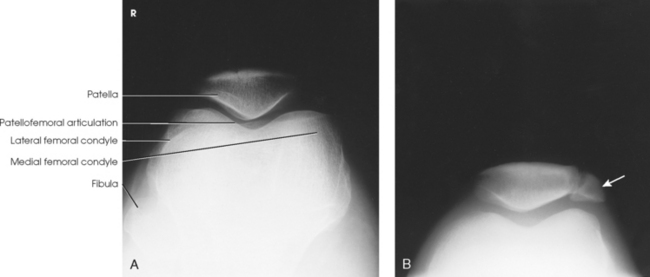
Structures shown: The image shows vertical fractures of bone and the articulating surfaces of the patellofemoral articulation (Figs. 6-162 and 6-163).
Femur
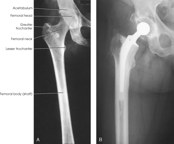
If the femoral heads are separated by an unusually broad pelvis, the bodies (shafts) are more strongly angled toward the midline.
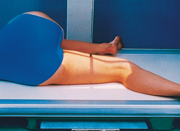
• Center the affected thigh to the midline of the IR. When the patient is too tall to include the entire femur, include the joint closest to the area of interest on one image (Fig. 6-164).
• For projection of the distal femur, rotate the patient’s limb internally to place it in true anatomic position. The limb is naturally turned externally when laying on the table. Ensure that the epicondyles are parallel with the IR.
• Place the bottom of the IR 2 inches (5 cm) below the knee joint.
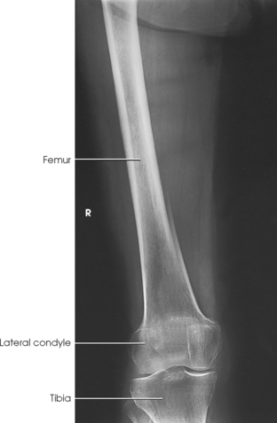
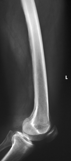
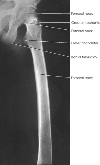
Structures shown: The resulting image shows an AP projection of the femur, including the knee joint or hip or both (Figs. 6-165 and 6-166).
The following should be clearly shown:
Evidence of proper collimation
Most of the femur and the joint nearest to the pathologic condition or site of injury (a second projection of the other joint is recommended)
Femoral neck not foreshortened on the proximal femur
Lesser trochanter not seen beyond the medial border of the femur or only a very small portion seen on the proximal femur
No knee rotation on the distal femur
Gonad shielding when indicated, but without the shield covering proximal femur
LATERAL PROJECTION
• For projection of the distal femur, draw the patient’s uppermost limb forward and support it at hip level on sandbags.
• Adjust the pelvis in a true lateral position (Fig. 6-167).
• Flex the affected knee about 45 degrees, place a sandbag under the ankle, and adjust the body rotation to place the epicondyles perpendicular to the tabletop.
• Adjust the position of the Bucky tray so that the IR projects approximately 2 inches (5 cm) beyond the knee to be included.
NOTE: This radiograph can also be accomplished using the part positions for “with the hip included.”
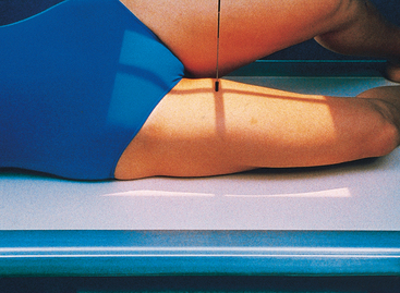
• For projection of the proximal femur, place the top of the IR at the level of the ASIS.
• Draw the upper limb posteriorly, and support it.
• Adjust the pelvis so that it is rolled posteriorly just enough to prevent superimposition; 10 to 15 degrees from the lateral position is sufficient (Fig. 6-168).
Structures shown: The image shows a lateral projection of about three fourths of the femur and the adjacent joint. If needed, use two IRs to show the entire length of the adult femur (Figs. 6-169 and 6-170).
The following should be clearly shown:
Evidence of proper collimation
Most of the femur and the joint nearest to the pathologic condition or site of injury (a second radiograph of the other end of the femur is recommended)
NOTE: Because of the danger of fragment displacement, the aforementioned position is not recommended for patients with fracture or patients who may have destructive disease. Patients with these conditions should be examined in the supine position by placing the IR vertically along the medial or lateral aspect of the thigh and knee and then directing the central ray horizontally. A wafer grid or a grid-front IR should be used to minimize scattered radiation.
Hips, Knees, and Ankles
Standing
NOTE: A specially built, long grid holder consisting of three grids, each 17 inches (43 cm) long, is required to hold the 51-inch (130-cm) IR and its trifold film. With computed radiography (CR), three separate 14- × 17-inch (35- × 43-cm) plates are held in a special long holder. The three individual images are “stitched” together using computer software.
SID: 8 ft (244 cm). This minimum-length SID is required to open the collimators wide enough to expose the entire 51-inch (130-cm) length of the IR.
• Have the patient stand on a 2-inch (5-cm) riser so that the ankle joint is visible on the image. The bottom of the grid unit is positioned behind and below the riser.
• Measure both lateral malleoli, and position the legs so that they are exactly 20 cm apart. If this distance cannot be achieved, measure the width of the malleoli and indicate this number on the request form. This image must be performed the same way for each return visit by the patient.
• Ensure that the patient’s toes are positioned straight forward in the anatomic position (Fig. 6-171).
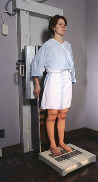
Fig. 6-171 Patient in position for radiograph of lower limbs: hips, knees, and ankles. The patient is placed in the anatomic position. The patient is standing on a raised platform so that the ankles are shown.
• Ensure that the patient is distributing weight equally on both feet.
• Mark with a right-side or left-side marker, and place a magnification marker in the area of the knee.
NOTE: A graduated speed screen (three sections and three speeds) may be used in place of a wedge filter.
 COMPENSATING FILTER
A compensating filter must be used for this projection (Fig. 6-172) because of the extreme difference between the hip joints and the ankle joints.
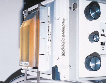
Fig. 6-172 Special filter for lower limb projections. Filter enables hips, knees, and ankles to be shown on one radiograph.
Structures shown: This projection shows the entire right and left limbs from the hip joint to the ankle joint (Fig. 6-173).
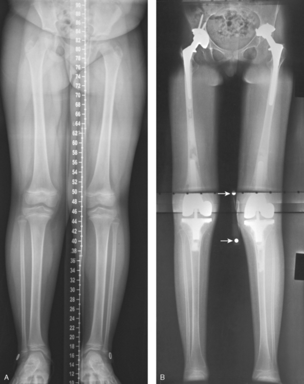
Fig. 6-173 Lower limbs: hips, knees, and ankles. A, Computed radiography (CR) “stitched” image. Computer created one image from three separate CR plates within a 51-inch (130-cm) IR. Note centimeter scale created within the image. B, A 51-inch (130-cm) radiographic film image. Arrows point to magnification marker taped to knee for measurements.
1Lewis RW: Nonroutine views in roentgen examination of the extremities, Surg Gynecol Obstet 67:38, 1938.
2Holly EW: Radiography of the tarsal sesamoid bones, Med Radiogr Photogr 31:73, 1955.
1Doub HP: A useful position for examining the foot, Radiology 16:764, 1931.
1Kite JH: Principles involved in the treatment of congenital clubfoot, J Bone Joint Surg 21:595, 1939.
2Kite JH: The clubfoot, New York, 1964, Grune & Stratton.
3Davis LA, Hatt WS: Congenital abnormalities of the feet, Radiology 64:818, 1955.
1Kite JH: Principles involved in the treatment of congenital clubfoot, J Bone Joint Surg 21:595, 1939.
2Kite JH: The clubfoot, New York, 1964, Grune & Stratton.
1Kandel B: The suroplantar projection in the congenital clubfoot of the infant, Acta Orthop Scand 22:161, 1952.
1Freiberger RH et al: Roentgen examination of the deformed foot, Semin Roentgenol 5:341, 1970.
1Lilienfeld L: Anordnung der normalisierten Röntgenaufnahmen des menschlichen Körpers, ed 4, Berlin, 1927, Urban & Schwarzenberg.
2Harris RI, Beath T: Etiology of peroneal spastic flat foot, J Bone Joint Surg Br 30:624, 1948.
3Coventry MB: Flatfoot with special consideration of tarsal coalition, Minn Med 33:1091, 1950.
4Vaughan WH, Segal G: Tarsal coalition, with special reference to roentgenographic interpretation, Radiology 60:855, 1953.
1Isherwood I: A radiological approach to the subtalar joint, J Bone Joint Surg Br 43:566, 1961.
2Feist JH, Mankin HJ: The tarsus: basic relationships and motions in the adult and definition of optimal recumbent oblique projection, Radiology 79:250, 1962.
1Ball RP, Egbert EW: Ruptured ligaments of the ankle, AJR Am J Roentgenol 50:770, 1943.
1Frank ED et al: Radiography of the ankle mortise, Radiol Technol 62:354, 1991.
1Martensen KM: Alternate AP knee method assures open joint space, Radiol Technol 64:19, 1992.
1Sheller S: Roentgenographic studies on epiphyseal growth and ossification in the knee, Acta Radiol 195:12, 1960.
1Leach RE et al: Weight-bearing radiography in osteoarthritis of the knee, Radiology 97:265, 1970.
1Rosenberg TD et al: The forty-five degree posteroanterior flexion weight-bearing radiograph of the knee, J Bone Joint Surg Am 70:1479, 1988.
1Holmblad EC: Postero-anterior x-ray view of the knee in flexion, JAMA 109:1196, 1937.
2Turner GW et al: Erect positions for “tunnel” views of the knee, Radiol Technol 55:640, 1983.
1Holmblad EC: Posteroanterior x-ray view of the knee in flexion, JAMA 109:1196, 1937.
1Camp JD, Coventry MB: Use of special views in roentgenography of the knee joint, US Naval Med Bull 42:56, 1944.
1Hughston JC: Subluxation of the patella, J Bone Joint Surg Am 50:1003, 1968.
2Kimberlin GE: Radiological assessment of the patellofemoral articulation and subluxation of the patella, Radiol Technol 45:129, 1973.
3Laurin CA: The abnormal lateral patellofemoral angle, J Bone Joint Surg Am 60:55, 1968.
4Fodor J et al: Accurate radiography of the patellofemoral joint, Radiol Technol 53:570, 1982.
5Merchant AC et al: Roentgenographic analysis of patellofemoral congruence, J Bone Joint Surg Am 56:1391, 1974.
6Hughston JC: Subluxation of the patella, J Bone Joint Surg Am 50:1003, 1968.
5Merchant AC et al: Roentgenographic analysis of patellofemoral congruence, J Bone Joint Surg Am 56:1391, 1974.
1Merchant AC et al: Roentgenographic analysis of patellofemoral congruence, J Bone Joint Surg Am 56:1391, 1974.
2Merchant AC: The Axial Viewer, Orthopedic Products, 2500 Hospital Dr., Bldg. 7, Mountain View, CA 94040.
1Krushell R et al: A comparison of the mechanical and anatomical axes in arthritic knees. In Proceedings of the Knee Society, 1985-1986, Aspen, CO, 1987.
2Peterson TD, Rohr W: Improved assessment of lower extremity alignment using new roentgenographic techniques, Clin Orthop Rel Res (219):112, 1987.