LOWER LIMB

SUMMARY OF PROJECTIONS
ANATOMY
The lower limb, or extremity, and its girdle (considered in Chapter 7) are studied in four parts: (1) foot, (2) leg, (3) thigh, and (4) hip. The bones are composed, shaped, and placed so that they can carry the body in the upright position and transmit its weight to the ground with a minimal amount of stress to the individual parts.
Foot
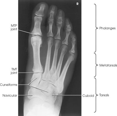
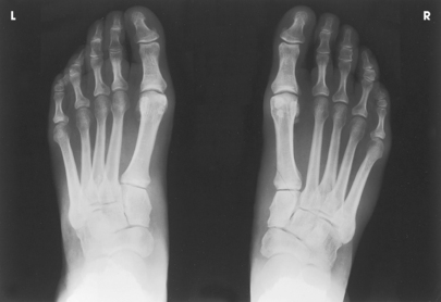
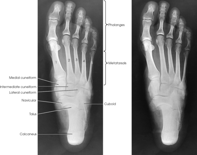
The foot consists of 26 bones (Figs. 6-1 and 6-2):
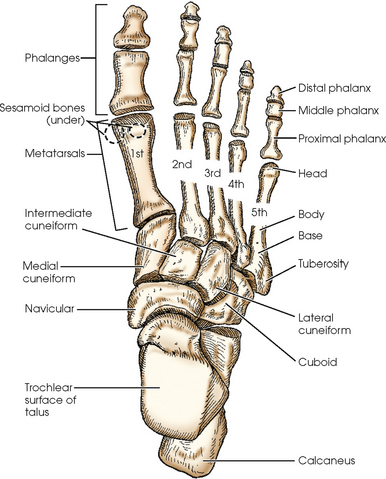
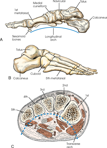
Fig. 6-2 Right foot. A, Medial aspect. B, Lateral aspect. C, Coronal section near base of metatarsals. Transverse arch shown.
The bones of the foot are similar to the bones of the hand. Structural differences permit walking and support of the body’s weight. For descriptive purposes, the foot is sometimes divided into the forefoot, midfoot, and hindfoot. The forefoot includes the metatarsals and toes. The midfoot includes five tarsals—the cuneiforms, navicular, and cuboid bones. The hindfoot includes the talus and calcaneus. The bones of the foot are shaped and joined together to form a series of longitudinal and transverse arches. The longitudinal arch functions as a shock absorber to distribute the weight of the body in all directions, which permits smooth walking (see Fig. 6-2). The transverse arch runs from side to side and assists in supporting the longitudinal arch. The superior surface of the foot is termed the dorsum or dorsal surface, and the inferior, or posterior, aspect of the foot is termed the plantar surface.
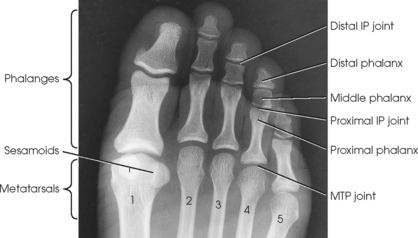
PHALANGES
Each foot has 14 phalanges—2 in the great toe and 3 in each of the other toes. The phalanges of the great toe are termed the distal and proximal phalanges. The phalanges of the other toes are termed the proximal, middle, and distal phalanges. Each phalanx is composed of a body and two expanded articular ends—the proximal base and the distal head.
METATARSALS
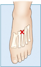
The five metatarsals are numbered one to five beginning at the medial or great toe side of the foot. The metatarsals consist of a body and two articular ends. The expanded proximal end is called the base, and the small, rounded distal end is termed the head. The five heads form the “ball” of the foot. The first metatarsal is the shortest and thickest. The second metatarsal is the longest. The base of the fifth metatarsal contains a prominent tuberosity, which is a common site of fractures.
TARSALS
The proximal foot contains seven tarsals (see Fig. 6-1):
Beginning at the medial side of the foot, the cuneiforms are described as medial, intermediate, and lateral.
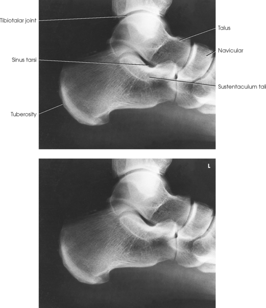
The calcaneus is the largest and strongest tarsal bone (Fig. 6-3). Some texts refer to it as the os calcis. It projects posteriorly and medially at the distal part of the foot. The long axis of the calcaneus is directed inferiorly and forms an angle of approximately 30 degrees. The posterior and inferior portions of the calcaneus contain the posterior tuberosity for attachment of the Achilles tendon. Superiorly, three articular facets join with the talus. They are called the anterior, middle, and posterior facets. Between the middle and posterior talar articular facets is a groove, the calcaneal sulcus, which corresponds to a similar groove on the inferior surface of the talus. Collectively, these sulci constitute the sinus tarsi. The interosseous ligament passes through this sulcus. The medial aspect of the calcaneus extends outward as a shelflike overhang and is termed the sustentaculum tali. The lateral surface of the calcaneus contains the trochlea.

Fig. 6-3 A, Articular surfaces of right calcaneus. B, Photograph of superior aspect of right calcaneus. Note three articular facet surfaces. C, Photograph of inferior aspect of talus. Note three articular surfaces that articulate with superior calcaneus.
The talus, irregular in form and occupying the superiormost position of the foot, is the second largest tarsal bone (see Figs. 6-1 to 6-3). The talus articulates with four bones—tibia, fibula, calcaneus, and navicular bone. The superior surface, the trochlear surface, articulates with the tibia and connects the foot to the leg. The head of the talus is directed anteriorly and has articular surfaces that join the navicular bone and calcaneus. On the inferior surface is a groove, the sulcus tali, that forms the roof of the sinus tarsi. The inferior surface also contains three facets that align with the facets on the superior surface of the calcaneus.
The cuboid bone lies on the lateral side of the foot between the calcaneus and the fourth and fifth metatarsals (see Fig. 6-1). The navicular bone lies on the medial side of the foot between the talus and the three cuneiforms. The cuneiforms lie at the central and medial aspect of the foot between the navicular bone and the first, second, and third metatarsals. The medial cuneiform is the largest of the three cuneiform bones, and the intermediate cuneiform is the smallest.
The seven tarsals can be remembered using the following mnemonic:
| Chubby | Calcaneus |
| Twisted, | Talus |
| Never | Navicular |
| Could | Cuboid |
| Cha | Cuneiform—medial |
| Cha | Cuneiform—intermediate |
| Cha | Cuneiform—lateral |
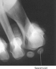
SESAMOID BONES
Beneath the head of the first metatarsal are two small bones called sesamoid bones. They are detached from the foot and embedded within two tendons. These bones are seen on most adult foot radiographs. They are a common site of fractures and must be shown radiographically (see Fig. 6-2).
Leg
The leg has two bones: the tibia and fibula. The tibia, the second largest bone in the body, is situated on the medial side of the leg and is a weight-bearing bone. Slightly posterior to the tibia on the lateral side of the leg is the fibula. The fibula does not bear any body weight.
TIBIA
The tibia (Fig. 6-4) is the larger of the two bones of the leg and consists of one body and two expanded extremities. The proximal end of the tibia has two prominent processes—the medial and lateral condyles. The superior surfaces of the condyles form smooth facets for articulation with the condyles of the femur. These two flatlike superior surfaces are called the tibial plateaus, and they slope posteriorly about 10 to 20 degrees. Between the two articular surfaces is a sharp projection, the intercondylar eminence, which terminates in two peaklike processes called the medial and lateral intercondylar tubercles. The lateral condyle has a facet at its distal posterior surface for articulation with the head of the fibula. On the anterior surface of the tibia, just below the condyles, is a prominent process called the tibial tuberosity, to which the ligamentum patellae attach. Extending along the anterior surface of the tibial body, beginning at the tuberosity, is a sharp ridge called the anterior crest.
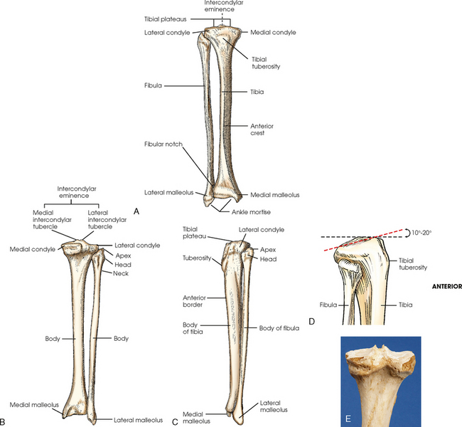
Fig. 6-4 Right tibia and fibula. A, Anterior aspect. B, Posterior aspect. C, Lateral aspect. D, Proximal end of tibia and fibula showing angle of tibial plateau. E, Photograph of superior and posterior aspect of the tibia.
The distal end of the tibia (Fig. 6-5) is broad, and its medial surface is prolonged into a large process called the medial malleolus. Its anterolateral surface contains the anterior tubercle, which overlays the fibula. The lateral surface is flattened and contains the triangular fibular notch for articulation with the fibula. The surface under the distal tibia is smooth and shaped for articulation with the talus.
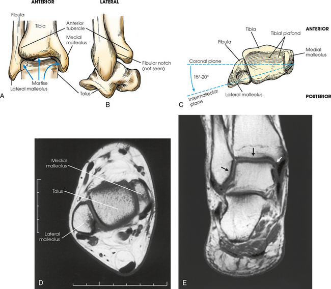
Fig. 6-5 Right distal tibia and fibula in true anatomic position. A, Mortise joint and surrounding anatomy. Note slight overlap of anterior tubercle of tibia and superolateral talus over fibula. B, Lateral aspect showing fibula positioned slightly posterior to tibia. C, Inferior aspect. Note lateral malleolus lies more posterior than medial malleolus. D, MRI axial plane of lateral and medial malleoli and talus. Lateral malleolus lies more posterior than medial malleolus. E, MRI coronal plane of ankle clearly showing ankle mortise joint (arrows).
FIBULA
The fibula is slender compared with its length and consists of one body and two articular extremities. The proximal end of the fibula is expanded into a head, which articulates with the lateral condyle of the tibia. At the lateroposterior aspect of the head is a conic projection called the apex. The enlarged distal end of the fibula is the lateral malleolus. The lateral malleolus is pyramidal and marked by several depressions at its inferior and posterior surfaces. Viewed axially, the lateral malleolus lies approximately 15 to 20 degrees more posterior than the medial malleolus (see Fig. 6-5, C).
Femur
The femur is the longest, strongest, and heaviest bone in the body (Figs. 6-6 and 6-7). This bone consists of one body and two articular extremities. The body is cylindric, slightly convex anteriorly, and slants medially 5 to 15 degrees (see Fig. 6-6, A). The extent of medial inclination depends on the breadth of the pelvic girdle. When the femur is vertical, the medial condyle is lower than the lateral condyle (see Fig. 6-6, C). About a 5- to 7-degree difference exists between the two condyles. Because of this difference, on lateral radiographs of the knee the central ray is angled 5 to 7 degrees cephalad to “open” the joint space of the knee. The superior portion of the femur articulates with the acetabulum of the hip joint (considered with the pelvic girdle in Chapter 7).
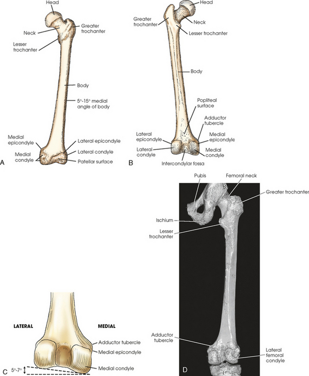
Fig. 6-6 A, Anterior aspect of left femur. B, Posterior aspect. C, Distal end of posterior femur showing 5- to 7-degree difference between medial and lateral condyle when femur is vertical. D, Three-dimensional CT scan showing posterior aspect and articulation with knee and hip.
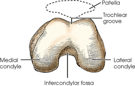
The distal end of the femur is broadened and has two large eminences: the larger medial condyle and the smaller lateral condyle. Anteriorly, the condyles are separated by the patellar surface, a shallow, triangular depression. Posteriorly, the condyles are separated by a deep depression called the intercondylar fossa. A slight prominence above and within the curve of each condyle forms the medial and lateral epicondyles. The medial condyle contains the adductor tubercle, which is located on the posterolateral aspect. The tubercle is a raised bony area that receives the tendon of the adductor muscle. This tubercle is important to identify on lateral knee radiographs because it assists in identifying overrotation or underrotation. The triangular area superior to the intercondylar fossa on the posterior femur is the trochlear groove, over which the popliteal blood vessels and nerves pass.
The posterior area of the knee, between the condyles, contains a sesamoid bone in 3% to 5% of people. This sesamoid is called the fabella and is seen only on the lateral projection of the knee.
Patella
The patella, or knee cap (Fig. 6-8), is the largest and most constant sesamoid bone in the body (see Chapter 3). The patella is a flat, triangular bone situated at the distal anterior surface of the femur. The patella develops in the tendon of the quadriceps femoris muscle between 3 and 5 years of age. The apex, or tip, is directed inferiorly, lies ½ inch (1.3 cm) above the joint space of the knee, and is attached to the tuberosity of the tibia by the patellar ligament. The superior border of the patella is called the base.
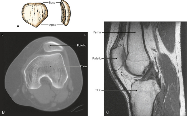
Fig. 6-8 A, Anterior and lateral aspects of patella. B, Axial CT scan of patella showing relationship to femur. C, Sagittal MRI showing patellar relationship to femur and knee joint. Apex of patella is ½ inch (1.2 cm) above knee joint. (B and C, Modified from Kelley LL, Petersen CM: Sectional anatomy for imaging professionals, ed 2, St Louis, 2007, Mosby.)
Knee Joint
The knee joint is one of the most complex joints in the human body. The femur, tibia, fibula, and patella are held together by a complex group of ligaments. These ligaments work together to provide stability for the knee joint. Although radiographers do not produce images of these ligaments, they need to have a basic understanding of their positions and interrelationship. Many patients with knee injuries do not have fractures, but they may have torn one or more of these ligaments, which can cause great pain and may alter the position of the bones. Fig. 6-9 shows the following important ligaments of the knee:
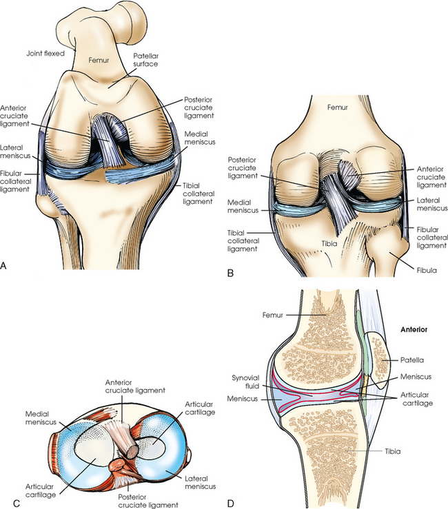
Fig. 6-9 Knee joint. A, Anterior aspect with femur flexed. B, Posterior aspect. C, Superior surface of tibia. D, Sagittal section.
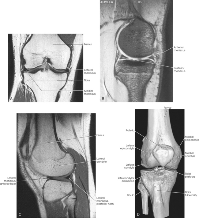
The knee joint contains two fibrocartilage disks called the lateral meniscus and medial meniscus (Fig. 6-10; see Fig. 6-9). The circular menisci lie on the tibial plateaus. They are thick at the outer margin of the joint and taper off toward the center of the tibial plateau. The center of the tibial plateau contains cartilage that articulates directly with the condyles of the knee. The menisci provide stability for the knee and act as a shock absorber. The menisci are commonly torn during injury. Either a knee arthrogram or a magnetic resonance imaging (MRI) scan must be performed to visualize a meniscus tear.
Lower Limb Articulations
The joints of the lower limb are summarized in Table 6-1 and shown in Figs. 6-11 and 6-12. Beginning with the distalmost portion of the lower limb, the articulations are as follows.
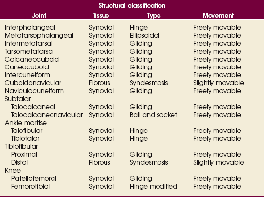
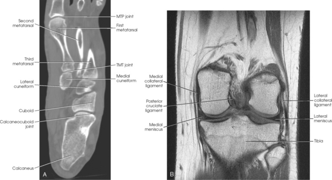
Fig. 6-11 A, Axial CT scan of foot and calcaneus. B, MRI coronal plane of knee joint. Joint spaces are clearly shown.
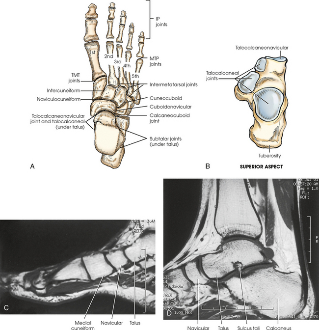
Fig. 6-12 A and B, Joints of right foot. C, MRI sagittal plane of anterior foot. D, MRI sagittal plane of posterior foot and ankle. Joint spaces and articular surfaces are clearly shown.
The interphalangeal (IP) articulations, between the phalanges, are synovial hinges that allow only flexion and extension. The joints between the distal and middle phalanges are the distal interphalangeal (DIP) joints. Articulations between the middle and proximal phalanges are the proximal interphalangeal (PIP) joints. With only two phalanges in the great toe, the joint is known simply as the IP joint.
The distal heads of the metatarsals articulate with the proximal ends of the phalanges at the metatarsophalangeal (MTP) articulations to form synovial ellipsoidal joints, which have movements of flexion, extension, and slight adduction and abduction. The proximal bases of the metatarsals articulate with one another (intermetatarsal articulations) and with the tarsals (tarsometatarsal [TMT] articulations) to form synovial gliding joints, which permit flexion, extension, adduction, and abduction movements.
The intertarsal articulations allow only slight gliding movements between the bones and are classified as synovial gliding or synovial ball-and-socket joints (see Table 6-1). The joint spaces are narrow and obliquely situated. When the joint surfaces of these bones are in question, it is necessary to angle the x-ray tube or adjust the foot to place the joint spaces parallel with the central ray.
The calcaneus supports the talus and articulates with it by an irregularly shaped, three-faceted joint surface, forming the subtalar joint. This joint is classified as a synovial gliding joint. Anteriorly, the calcaneus articulates with the cuboid at the calcaneocuboid joint. This joint is a synovial gliding joint. The talus rests on top of the calcaneus (see Fig. 6-12). It articulates with the navicular bone anteriorly, supports the tibia above, and articulates with the malleoli of the tibia and fibula at its sides.
Each of the three parts of the subtalar joint is formed by reciprocally shaped facets on the inferior surface of the talus and the superior surface of the calcaneus. Study of the superior and medial aspects of the calcaneus (see Fig. 6-3) helps the radiographer to understand better the problems involved in radiography of this joint.
The intertarsal articulations are as follows:
The ankle joint is commonly called the ankle mortise, or mortise joint. It is formed by the articulations between the lateral malleolus of the fibula and the inferior surface and medial malleolus of the tibia (Fig. 6-13, A). The mortise joint is often divided specifically into the talofibular and tibiofibular joints. These form a socket type of structure that articulates with the superior portion of the talus. The talus fits inside the mortise. The articulation is a synovial hinge type of joint. The primary action of the ankle joint is dorsiflexion (flexion) and plantar flexion (extension); however, in full plantar flexion, a small amount of rotation and abduction-adduction is permitted. The mortise joint also allows inversion and eversion of the foot. Other movements at the ankle largely depend on the gliding movements of the intertarsal joints, particularly the one between the talus and calcaneus.
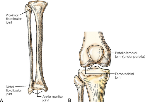
The fibula articulates with the tibia at its distal and proximal ends. The distal tibiofibular joint is a fibrous syndesmosis joint allowing slight movement. The head of the fibula articulates with the posteroinferior surface of the lateral condyle of the tibia, which forms the proximal tibiofibular joint, which is a synovial gliding joint (see Fig. 6-13, A).
The patella articulates with the patellar surface of the femur and protects the front of the knee joint. This articulation is called the patellofemoral joint; when the knee is extended and relaxed, the patella is freely movable over the patellar surface of the femur. When the knee is flexed, which is also a synovial gliding joint, the patella is locked in position in front of the patellar surface. The knee joint, or femorotibial joint, is the largest joint in the body. It is called a synovial modified-hinge joint. In addition to flexion and extension, the knee joint allows slight medial and lateral rotation in the flexed position. The joint is enclosed in an articular capsule and held together by numerous ligaments (see Figs. 6-9 and 6-13, B).
SUMMARY OF PATHOLOGY
| Condition | Definition |
| Bone cyst | Fluid-filled cyst with a wall of fibrous tissue |
| Congenital clubfoot | Abnormal twisting of the foot, usually inward and downward |
| Dislocation | Displacement of a bone from the joint space |
| Fracture | Disruption in the continuity of bone |
| Pott | Avulsion fracture of the medial malleolus with loss of the ankle mortise |
| Jones | Avulsion fracture of the base of the fifth metatarsal |
| Gout | Hereditary form of arthritis in which uric acid is deposited in joints |
| Metastases | Transfer of a cancerous lesion from one area to another |
| Osgood-Schlatter disease | Incomplete separation or avulsion of the tibial tuberosity |
| Osteoarthritis or degenerative joint disease | Form of arthritis marked by progressive cartilage deterioration in synovial joints and vertebrae |
| Osteomalacia or rickets | Softening of the bones owing to vitamin D deficiency |
| Osteomyelitis | Inflammation of bone owing to a pyogenic infection |
| Osteopetrosis | Increased density of atypically soft bone |
| Osteoporosis | Loss of bone density |
| Paget disease | Chronic metabolic disease of bone marked by weakened, deformed, and thickened bone that fractures easily |
| Tumor | New tissue growth where cell proliferation is uncontrolled |
| Chondrosarcoma | Malignant tumor arising from cartilage cells |
| Enchondroma | Benign tumor consisting of cartilage |
| Ewing sarcoma | Malignant tumor of bone arising in medullary tissue |
| Osteochondroma or exostosis | Benign bone tumor projection with a cartilaginous cap |
| Osteoclastoma or giant cell tumor | Lucent lesion in the metaphysis, usually at the distal femur |
| Osteoid osteoma | Benign lesion of cortical bone |
| Osteosarcoma | Malignant, primary tumor of bone with bone or cartilage formation |
EXPOSURE TECHNIQUE CHART ESSENTIAL PROJECTIONS
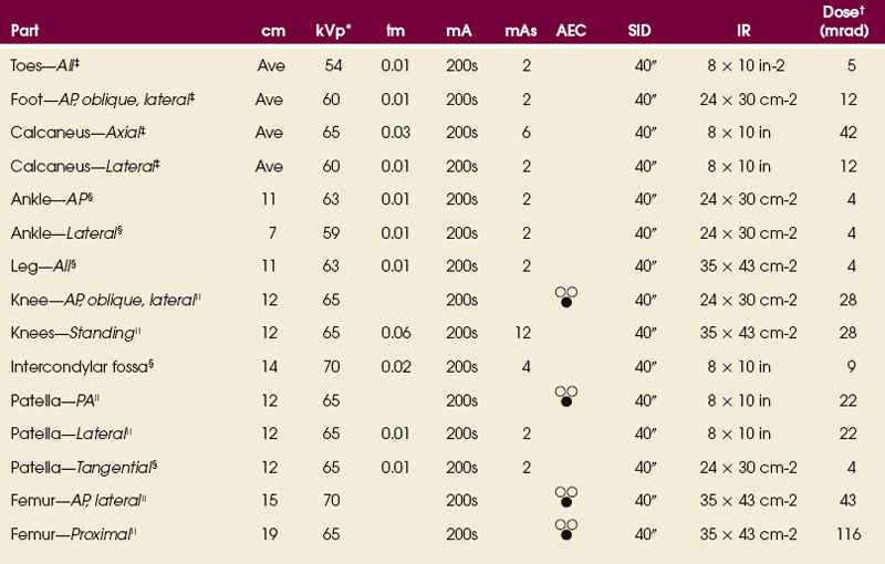
*kVp values are for a three-phase, 12-pulse generator or high frequency.
†Relative doses for comparison use. All doses are skin entrance for average adult at cm indicated.
‡Tabletop, extremity IR. Screen-film speed 100.
§Tabletop, standard IR. Screen-film speed 300 or equivalent CR.
|Bucky, 16:1 grid. Screen-film speed 300.
Radiation Protection
Protecting the patient from unnecessary radiation is a professional responsibility of the radiographer (see Chapter 1 for specific guidelines). In this chapter, the Shield gonads statement at the end of the Position of part sections indicates that the patient is to be protected from unnecessary radiation by restricting the radiation beam, using proper collimation, and placing lead shielding between the gonads and the radiation source.
Toes
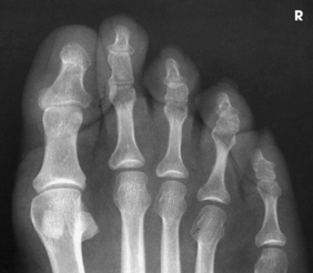
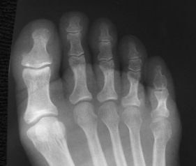
Because of the natural curve of the toes, the IP joint spaces are not best shown on the AP projection. When demonstration of these joint spaces is not critical, an AP projection may be performed (Figs. 6-14 and 6-15). An AP axial projection is recommended to open the joint spaces and reduce foreshortening (Figs. 6-16 and 6-17).


• With the patient in the supine or seated position, flex the knees, separate the feet about 6 inches (15 cm), and touch the knees together for immobilization.
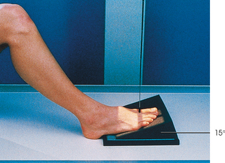
• Center the toes directly over one half of the IR (see Figs. 6-14 and 6-16), or place a 15-degree foam wedge well under the foot and rest the toes near the elevated base of the wedge (Fig. 6-18).
• Adjust the IR half with its midline parallel to the long axis of the foot, and center it to the third MTP joint.
NOTE: Some institutions may show the entire foot, whereas others radiograph only the toe or toes of interest.
• Perpendicular through the third MTP joint (see Fig. 6-14) when showing the joint spaces is not critical. To open the joint spaces, either direct the central ray 15 degrees posteriorly through the third MTP joint (see Fig. 6-16), or if the 15-degree foam wedge is used, direct the central ray perpendicularly (Fig. 6-19).
PA PROJECTION
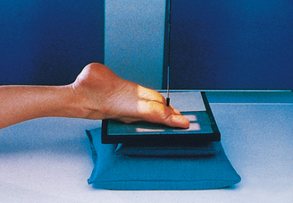
• Place the toes in the appropriate position by elevating them on one or two small sandbags and adjusting the support to place the toes horizontal.
• Place the IR half under the toes with the midline of the side used parallel with the long axis of the foot, and center it to the third MTP joint (Fig. 6-20).
 AP OBLIQUE PROJECTION
• Position the IR half under the toes.
• Medially rotate the lower leg and foot, and adjust the plantar surface of the foot to form a 30- to 45-degree angle from the plane of the IR (Fig. 6-22).
NOTE: Oblique projections of individual toes may be obtained by centering the affected toe to the portion of the IR being used and collimating closely. The foot may be placed in a medial oblique position for the first and second toes and in a lateral oblique position for the fourth and fifth toes. Either oblique position is adequate for the third (middle) toe.
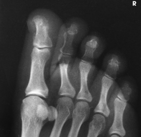
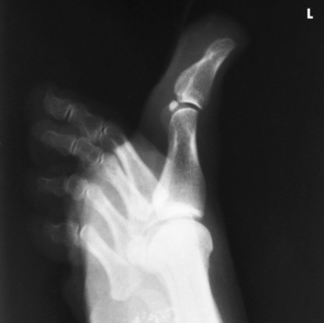
Structures shown: An AP oblique projection of the phalanges shows the toes and the distal portion of the metatarsals rotated medially (Fig. 6-23).
LATERAL PROJECTIONS
• Place the patient on the unaffected side for these two toes.
• Place an 8 × 10 inch (18 × 24 cm) IR under the toe, and center it to the proximal phalanx.
• Grasp the patient’s limb by the heel and knee, and adjust its position to place the toe in a true lateral position (plane through MTP joints will be perpendicular to IR).
• Adjust the long axis of the IR so that it is parallel with the long axis of the toe (Figs. 6-24 and 6-25).
• Place the patient on the affected side for these three toes.
• Select an 8 × 10 inch (18 × 24 cm) IR.
• Grasp patient’s limb by heel and knee, and adjust its position to place the toes in a true lateral position (plane through MTP joints is perpendicular to IR).
• Adjust the position of the limb to place the toe of interest and the IR or film in a parallel position, placing the toe as close to the IR or film as possible.
• Support the elevated heel on a sandbag or sponge for immobilization (Figs. 6-26 to 6-28).
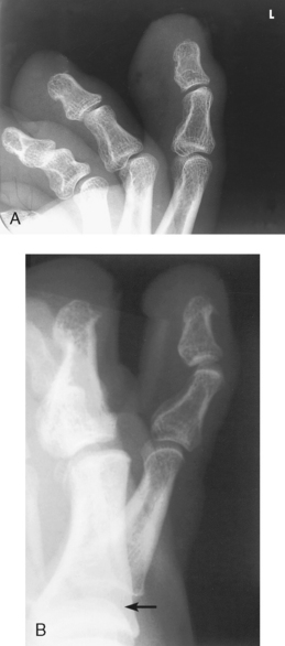
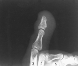
Structures shown: Images show a lateral projection of the phalanges of the toe and the IP articulations projected free of the other toes (Figs. 6-29 to 6-33).
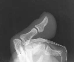

Sesamoids
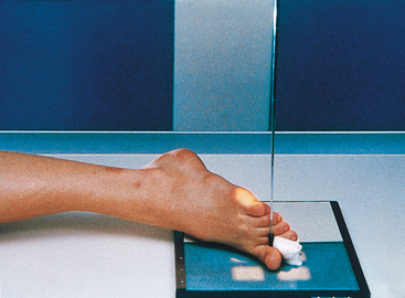
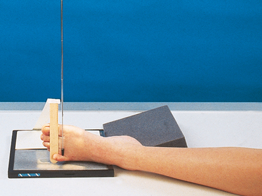
• Rest the great toe on the table in a position of dorsiflexion, and adjust it to place the ball of the foot perpendicular to the horizontal plane.
• Center the IR to the second metatarsal (Fig. 6-34).
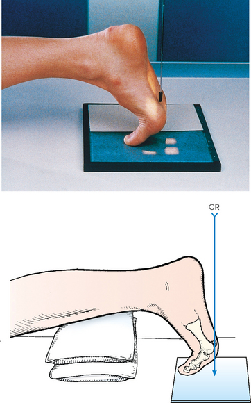
Structures shown: The resulting image shows a tangential projection of the metatarsal head in profile and the sesamoids (Fig. 6-35).
The following should be clearly shown:
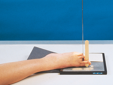
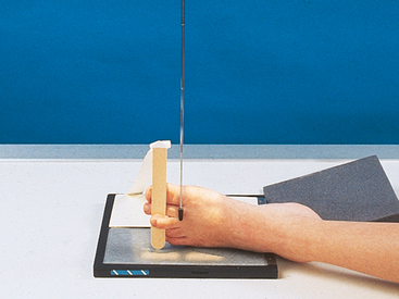
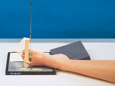
NOTE: Holly1 described a position that he believed was more comfortable for the patient. With the patient seated on the table, the foot is adjusted so that the medial border is vertical, and the plantar surface is at an angle of 75 degrees with the plane of the IR. The patient holds the toes in a flexed position with a strip of gauze bandage. The central ray is directed perpendicular to the head of the first metatarsal bone (Figs. 6-36 to 6-38).
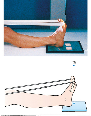
1Holly EW: Radiography of the tarsal sesamoid bones, Med Radiogr Photogr 31:73, 1955.
Foot
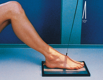
Radiographs may be obtained by directing the central ray perpendicular to the plane of the IR or by angling the central ray 10 degrees posteriorly. When a 10-degree posterior angle is used, the central ray is perpendicular to the metatarsals, reducing foreshortening. The TMT joint spaces of the midfoot are also better shown (Figs. 6-39 and 6-40).
• Position the IR under the patient’s foot, center it to the base of the third metatarsal, and adjust it so that its long axis is parallel with the long axis of the foot.
• Hold the leg in the vertical position by having the patient flex the opposite knee and lean it against the knee of the affected side.
• In this foot position, the entire plantar surface rests on the IR; it is necessary to take precautions against the IR slipping.
• Directed one of two ways: (1) 10 degrees toward the heel entering the base of the third metatarsal (see Fig. 6-39) or (2) perpendicular to the IR and entering the base of the third metatarsal (Fig. 6-41). Palpating the prominent base of the fifth metatarsal assists in finding the third metatarsal. The third metatarsal base is in the midline, approximately 1 inch anterior (toward the toes) (Fig. 6-42).
 COMPENSATING FILTER
This projection can be improved with the use of a wedge-type compensating filter because of the difference in thickness between the toe area and the much thicker tarsal area (see Fig. 6-44).
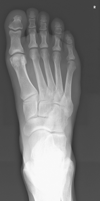
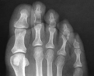
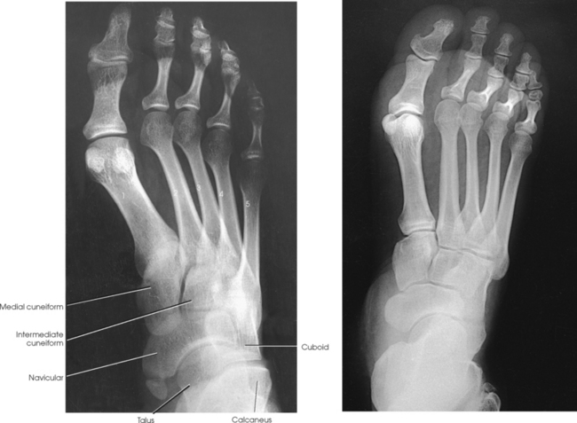
Structures shown: The resulting image shows an AP (dorsoplantar) projection of the tarsals anterior to the talus, metatarsals, and phalanges (Figs. 6-43 to 6-45). This projection is used for localizing foreign bodies, determining the location of fragments in fractures of the metatarsals and anterior tarsals, and performing general surveys of the bones of the foot.
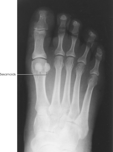
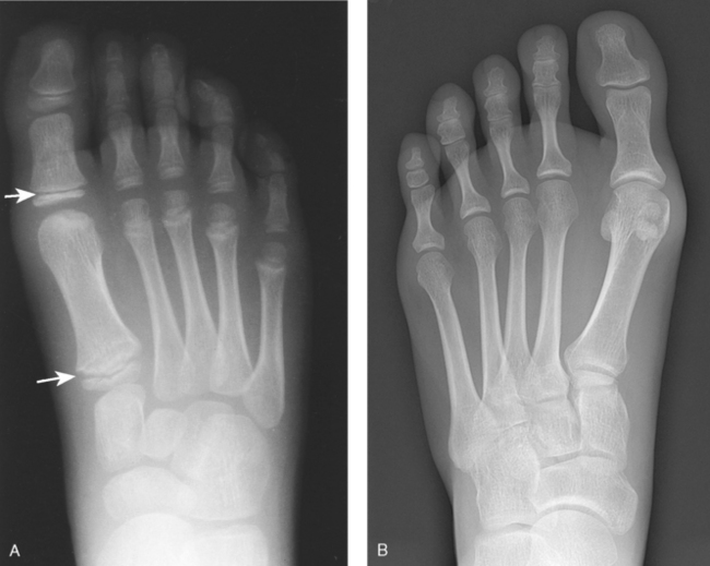
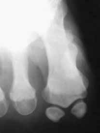
Fig. 6-45 A, AP foot of a 6-year-old patient. Note epiphyseal lines (arrows). B, AP foot showing well-penetrated tarsal bones.
AP OBLIQUE PROJECTION
NOTE: The medial oblique is preferred over the lateral oblique because the plane through the metatarsals is more parallel to the IR, and it opens the lateral side joints of the midfoot and hindfoot better.
• Place the IR under the patient’s foot, parallel with its long axis, and center it to the midline of the foot at the level of the base of the third metatarsal.
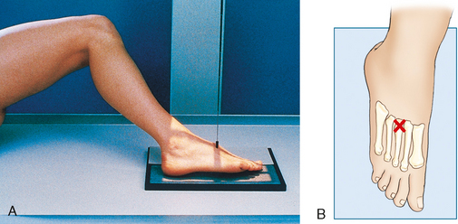
• Rotate the patient’s leg medially until the plantar surface of the foot forms an angle of 30 degrees to the plane of the IR (Fig. 6-46). If the angle of the foot is increased more than 30 degrees, the lateral cuneiform tends to be thrown over the other cuneiforms.1
COMPENSATING FILTER
This projection can be improved with the use of a wedge-type compensating filter because of the difference in thickness between the toe area and the much thicker tarsal area.
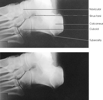
Structures shown: The resulting image shows the interspaces between the following: the cuboid and the calcaneus, the cuboid and the fourth and fifth metatarsals, the cuboid and the lateral cuneiform, and the talus and the navicular bone. The cuboid is shown in profile. The sinus tarsi is also well shown (Fig. 6-47).
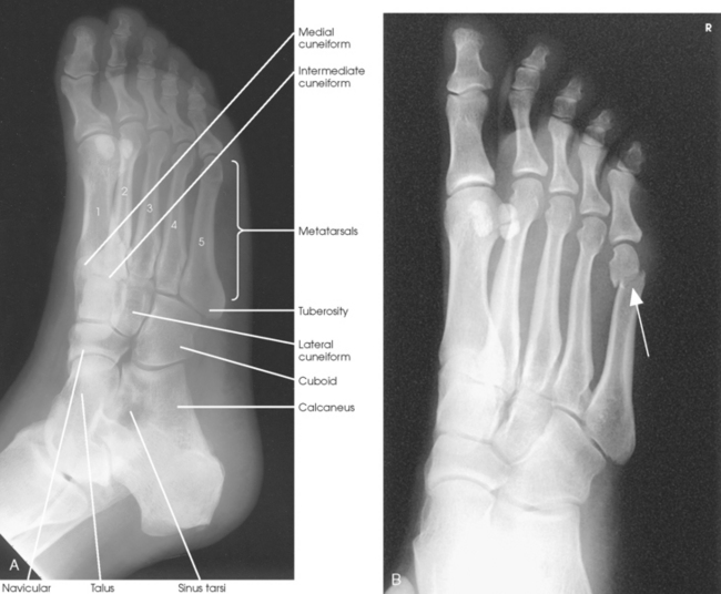
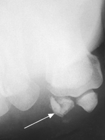
Fig. 6-47 A, AP oblique projection foot, medial rotation. B, Fracture of distal aspect of fifth metatarsal (arrow). Calcaneus was not included, and technique was adjusted to visualize distal foot better.
The following should be clearly shown:
 Evidence of proper collimation
Third through fifth metatarsal bases free of superimposition
Lateral tarsals with less superimposition than in the AP projection
Lateral TMT and intertarsal joints
Tuberosity of the fifth metatarsal
Bases of the first and second metatarsals superimposed on medial and intermediate cuneiforms.
Equal amount of space between the shafts of the second through fifth metatarsals
Sufficient density to show the phalanges, metatarsals, and tarsals
AP OBLIQUE PROJECTION
• Place the IR under the patient’s foot, parallel with its long axis, and center it to the midline of the foot at the level of the base of the third metatarsal.
• Rotate the leg laterally until the plantar surface of the foot forms an angle of 30 degrees to the IR.
• Support the elevated side of the foot on a 30-degree foam wedge to ensure consistent results (Fig. 6-48).
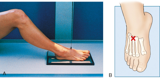
Structures shown: The resulting image shows the interspaces between the first and second metatarsals and between the medial and intermediate cuneiforms (Fig. 6-49).
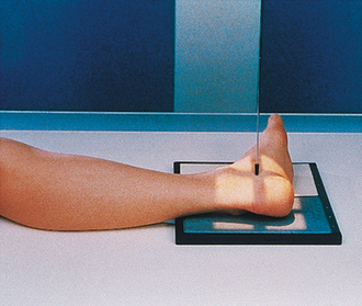
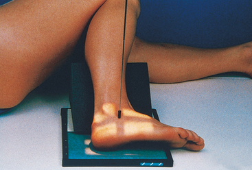
LATERAL PROJECTION
The lateral (mediolateral) projection is routinely used in most radiology departments because it is the most comfortable position for the patient to assume.
• Elevate the patient’s knee enough to place the patella perpendicular to the horizontal plane, and adjust a sandbag support under the knee.
• Adjust the foot to place the plantar surface of the forefoot perpendicular to the IR (Fig. 6-50).
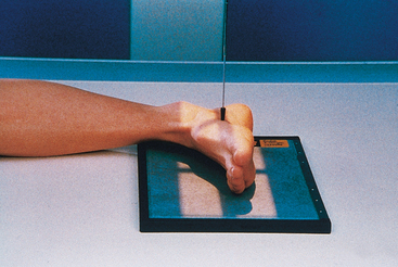
• Center the IR to the midfoot, and adjust it so that its long axis is parallel with the long axis of the foot.
• Dorsiflex the foot to form a 90-degree angle with the lower leg.
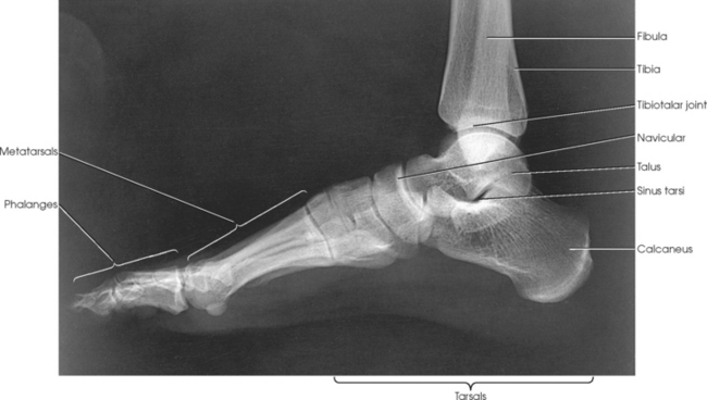
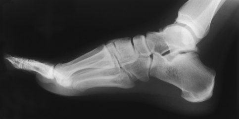
Structures shown: The resulting image shows the entire foot in profile, the ankle joint, and the distal ends of the tibia and fibula (Figs. 6-51 and 6-52).
Longitudinal Arch
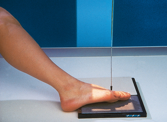
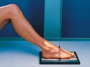
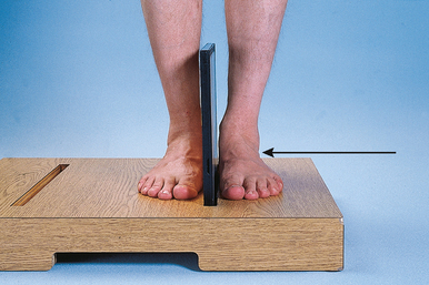
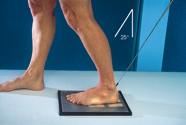
Standing
• Place the patient in the upright position, preferably on a low riser that has an IR groove. If such a riser is unavailable, use blocks to elevate the feet to the level of the x-ray tube (Figs. 6-53 and 6-54).

• If needed, use a mobile unit to allow the x-ray tube to reach the floor level.
• Place the IR in the IR groove of the stool or between blocks.
• Have the patient stand in a natural position, one foot on each side of the IR, with the weight of the body equally distributed on the feet.
• Adjust the IR so that it is centered to the base of the third metatarsal.
• After the exposure, replace the IR and position the new one to image the opposite foot.
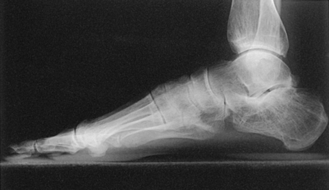
Structures shown: The resulting image shows a lateromedial projection of the bones of the foot with weight-bearing. The projection is used to show the structural status of the longitudinal arch. The right and left sides are examined for comparison (Figs. 6-55 and 6-56).
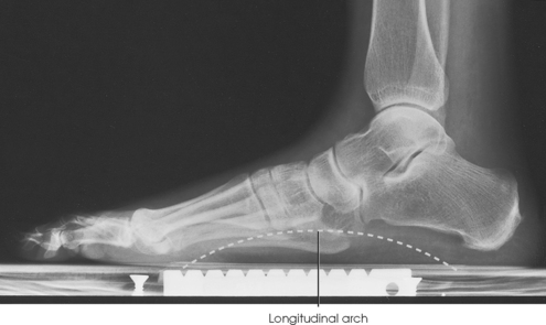
Fig. 6-55 Weight-bearing lateral foot showing centimeter measuring scale built into standing platform.
Feet
Standing
SID: 48 inches (122 cm). This SID is used to reduce magnification and improve recorded detail in the image.
• Place the IR on the floor, and have the patient stand on the IR with the feet centered on each side.
• Pull the patient’s pant legs up to the knee level, if necessary.
• Ensure that right and left markers and an upright marker are placed on the IR.
• Ensure that the patient’s weight is distributed equally on each foot (Fig. 6-57).
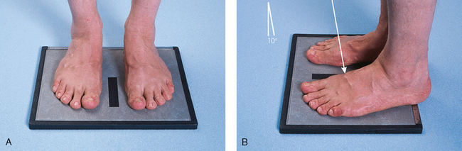
Fig. 6-57 Weight-bearing AP both feet, standing. A, Correct position of both feet on IR. B, Lateral perspective of same projection shows position of feet on IR and central ray.
Structures shown: The resulting image shows a weight-bearing AP axial projection of both feet, permitting an accurate evaluation and comparison of the tarsals and metatarsals (Fig. 6-58).
Foot
WEIGHT-BEARING COMPOSITE METHOD
Standing
• With the patient standing upright, adjust the IR under the foot and center its midline to the long axis of the foot.
• To prevent superimposition of the leg shadow on that of the ankle joint, have the patient place the opposite foot one step backward for the exposure of the forefoot and one step forward for the exposure of the hindfoot or calcaneus.
• To use the masking effect of the leg, direct the central ray along the plane of alignment of the foot in both exposures.
• With the tube in front of the patient and adjusted for a posterior angulation of 15 degrees, center the central ray to the base of the third metatarsal for the first exposure (Figs. 6-59 and 6-60).


• Caution the patient to maintain the position of the affected foot carefully and to place the opposite foot one step forward in preparation for the second exposure.
• Move the tube behind the patient, adjust it for an anterior angulation of 25 degrees, and direct the central ray to the posterior surface of the ankle. The central ray emerges on the plantar surface at the level of the lateral malleolus (Figs. 6-61 and 6-62). An increase in technical factors is recommended for this exposure.
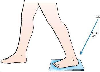
Structures shown: The resulting image shows a weightbearing AP axial projection of all bones of the foot. The full outline of the foot is projected free of the leg (Fig. 6-63).
Congenital Clubfoot
The typical clubfoot, or talipes equinovarus, shows three deviations from the normal alignment of the foot in relation to the weight-bearing axis of the leg. These deviations are plantar flexion and inversion of the calcaneus (equinus), medial displacement of the forefoot (adduction), and elevation of the medial border of the foot (supination). The typical clubfoot has numerous variations. Each of the typical abnormalities just described has varying degrees of deformity.
The classic Kite methods12—exactly placed AP and lateral projections—for radiography of the clubfoot are used to show the anatomy of the foot and the bones or ossification centers of the tarsals and their relation to one another. A primary objective makes it essential that no attempt be made to change the abnormal alignment of the foot when placing it on the IR. Davis and Hatt3 stated that even slight rotation of the foot can result in marked alteration in the radiographically projected relation of the ossification centers.
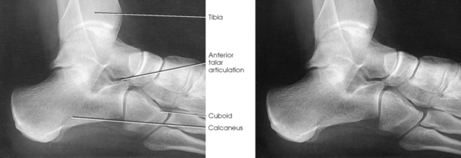
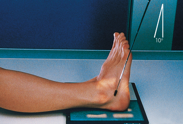
The AP projection shows the degree of adduction of the forefoot and the degree of inversion of the calcaneus.
• Rest the feet flat on the IR with the ankles extended slightly to prevent superimposition of the leg shadow.
• Hold the infant’s knees together or in such a way that the legs are exactly vertical (i.e., so that they do not lean medially or laterally).
• Using a lead glove, hold the infant’s toes. When the adduction deformity is too great to permit correct placement of the legs and feet for bilateral images without overlap of the feet, they must be examined separately (Figs. 6-64 and 6-65).
• Perpendicular to the tarsals, midway between the tarsal areas for a bilateral projection
• An approximately 15-degree posterior angle is generally required for the central ray to be perpendicular to the tarsals.
• Kite12 stressed the importance of directing the central ray vertically for the purpose of projecting the true relationship of the bones and ossification centers.
Congenital Clubfoot
Mediolateral
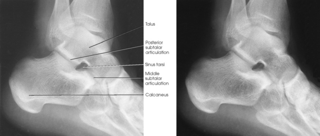
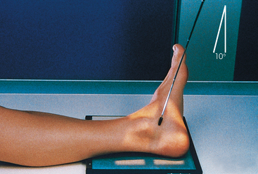
The Kite method lateral radiograph shows the anterior talar subluxation and the degree of plantar flexion (equinus).
• After adjusting the IR under the foot, place a support that has the same thickness as the IR under the infant’s knee to prevent angulation of the foot and to ensure a lateral foot position.
• Hold the infant’s toes in position with tape or a protected hand (Figs. 6-66 to 6-70).
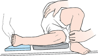
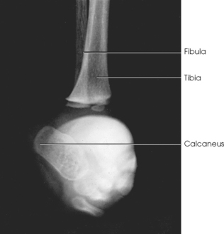
Fig. 6-67 Lateral foot projection showing pitch of calcaneus. Other tarsals are obscured by adducted forefoot.
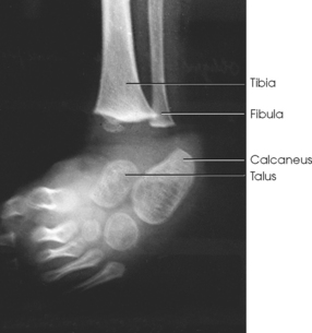
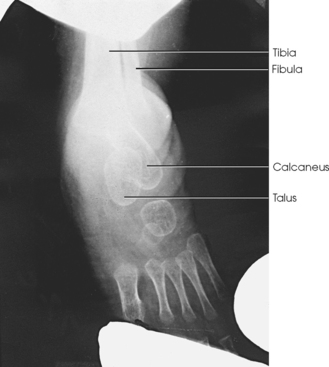
Fig. 6-69 AP projection after treatment (same patient as in Fig. 6-68).
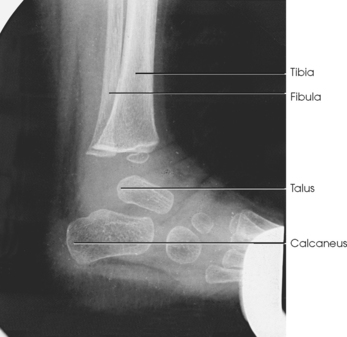
Fig. 6-70 Lateral projection after treatment (same patient as in Fig. 6-67).
The following should be clearly shown:
No medial or lateral angulation of the leg
Fibula in lateral projection overlapping the posterior half of the tibia
The need for a repeat examination if slight variations in rotation are seen in either image compared with previous radiographs
Sufficient density of the talus, calcaneus, and metatarsals to allow assessment of alignment variations
NOTE: Freiberger et al.1 recommended that dorsiflexion of an infant’s foot could be obtained by pressing a small plywood board against the sole of the foot. An older child or adult is placed in the upright position for a horizontal projection. With the upright position, the patient leans the leg forward to dorsiflex the foot.
NOTE: Conway and Cowell2 recommended tomography to show coalition at the middle facet and particularly the hidden coalition involving the anterior facet.
1Freiberger RH et al: Roentgen examination of the deformed foot, Semin Roentgenol 5:341, 1970.
2Conway JJ, Cowell HR: Tarsal coalition: clinical significance and roentgenographic demonstration, Radiology 92:799, 1969.
Congenital Clubfoot
Dorsoplantar
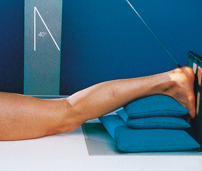
Kandel1 recommended the inclusion of a dorsoplantar axial projection in the examination of the patient with a clubfoot (Fig. 6-71).
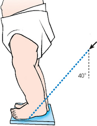
For this method, the infant is held in a vertical or a bending-forward position. The plantar surface of the foot should rest on the IR, although a moderate elevation of the heel is acceptable when the equinus deformity is well marked. The central ray is directed 40 degrees anteriorly through the lower leg, as for the usual dorsoplantar projection of the calcaneus (Fig. 6-72).
Freiberger et al.1 stated that sustentaculum talar joint fusion cannot be assumed on one projection because the central ray may not have been parallel with the articular surfaces. They recommended that three radiographs be obtained with varying central ray angulations (35, 45, and 55 degrees).
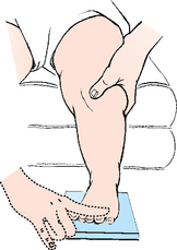
Calcaneus
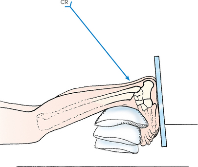
Plantodorsal
• Place the IR under the patient’s ankle, centered to the midline of the ankle (Figs. 6-73 and 6-74).

• Place a long strip of gauze around the ball of the foot. Have the patient grasp the gauze to hold the ankle in right-angle dorsiflexion.
• If the patient’s ankles cannot be flexed enough to place the plantar surface of the foot perpendicular to the IR, elevate the leg on sandbags to obtain the correct position.
COMPENSATING FILTER
This projection can be improved significantly with the use of a compensating filter because of the increased density through the midportion of the foot.
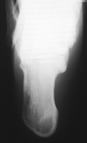
Structures shown: The resulting image shows an axial projection of the calcaneus (Fig. 6-75).
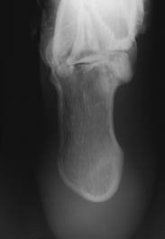
Fig. 6-75 Axial (plantodorsal) calcaneus. Image made using Ferlic swimmer’s filter. Note penetration of anterior calcaneus and metatarsal joint spaces.
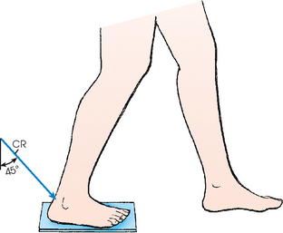
AXIAL PROJECTION
• Elevate the patient’s ankle on sandbags.
• Adjust the height and position of the sandbags under the ankle in such a way that the patient can dorsiflex the ankle enough to place the long axis of the foot perpendicular to the tabletop.
• Place the IR against the plantar surface of the foot, and support it in position with sandbags or a portable IR holder (Figs. 6-76 and 6-77).
COMPENSATING FILTER
This projection can be improved significantly with the use of a compensating filter because of the increased density through the midportion of the foot.
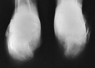
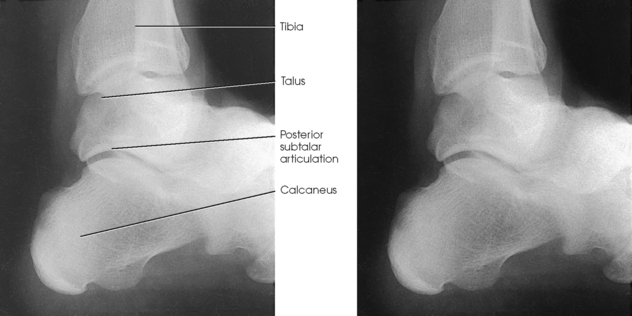
Structures shown: The resulting image shows an axial projection of the calcaneus and the subtalar joint (Fig. 6-78). CT is often used to show this bone (Fig. 6-79).
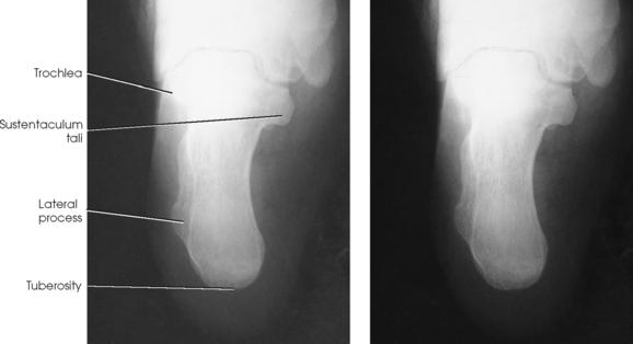
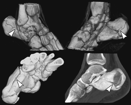
Fig. 6-79 CT images of calcaneal fracture with three-dimensional reconstruction. Conventional x-ray shows most fractures; however, complex regions, such as calcaneal-talar area, are best shown on CT. Note how bone (arrows) shows extent of fracture. (From Jackson SA, Thomas RM: Cross-sectional imaging made easy, New York, 2004, Churchill Livingstone.) Churchill Livingstone
WEIGHT-BEARING COALITION METHOD
This weight-bearing method, described by Lilienfeld1 (cit. Holzknecht), has come into use to show calcaneotalar coalition.234 For this reason, it has been called the coalition position.
• Center the IR to the long axis of the calcaneus, with the posterior surface of the heel at the edge of the IR.
• To prevent superimposition of the leg shadow, have the patient place the opposite foot one step forward (Fig. 6-80).
LATERAL PROJECTION
LATEROMEDIAL OBLIQUE PROJECTION
• Have the patient stand with the affected heel centered toward the lateral border of the IR (Fig. 6-83).

• A mobile radiographic unit may assist in this examination.
Structures shown: The resulting image shows the calcaneal tuberosity and is useful in diagnosing stress fractures of the calcaneus or tuberosity (Fig. 6-84).
Subtalar Joint
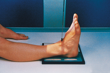
LATEROMEDIAL OBLIQUE PROJECTION
Medial rotation foot
Isherwood1 devised a method for each of the three separate articulations of the subtalar joint: (1) a medial rotation foot position to show the anterior talar articulation, (2) a medial rotation ankle position to show the middle talar articulation, and (3) a lateral rotation ankle position to show the posterior talar articulation. Feist and Mankin2 later described a similar position.
• With the medial border of the foot resting on the IR, place a 45-degree foam wedge under the elevated leg.
• Adjust the leg so that its long axis is in the same plane as the central ray.
• Adjust the foot to be at a right angle.
• Place a support under the knee (Fig. 6-85).
Structures shown: The resulting image shows the anterior subtalar articulation and an oblique projection of the tarsals (Fig. 6-86). The Feist-Mankin method produces a similar image representation.
AP AXIAL OBLIQUE PROJECTION
Medial rotation ankle
• Ask the patient to rotate the leg and foot medially enough to rest the side of the foot and affected ankle on an optional 30-degree foam wedge (Fig. 6-87).
• Place a support under the knee. If the patient is recumbent, place another support under the greater trochanter.
• Dorsiflex the foot, then invert it if possible, and have the patient maintain the position by pulling on a strip of 2- or 3-inch (5- to 7.6-cm) bandage looped around the ball of the foot.
Structures shown: The resulting image shows the middle articulation of the subtalar joint and an “end-on” projection of the sinus tarsi (Fig. 6-88).
AP AXIAL OBLIQUE PROJECTION
Lateral rotation ankle
• Ask the patient to rotate the leg and foot laterally until the side of the foot and ankle rests against an optional 30-degree foam wedge.
• Dorsiflex the foot, evert it if possible, and have the patient maintain the position by pulling on a broad bandage looped around the ball of the foot (Fig. 6-89).
Structures shown: The resulting image shows the posterior articulation of the subtalar joint in profile (Fig. 6-90).
Ankle
Image receptor: 8 × 10 inch (18 × 24 cm) lengthwise or 10 × 12 inch (24 × 30 cm) crosswise for two images on one IR
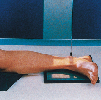
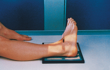
• Adjust the ankle joint in the anatomic position (foot pointing straight up) to obtain a true AP projection. Flex the ankle and foot enough to place the long axis of the foot in the vertical position (Fig. 6-91).
• Ball and Egbert1 stated that the appearance of the ankle mortise is not appreciably altered by moderate plantar flexion or dorsiflexion as long as the leg is rotated neither laterally nor medially.
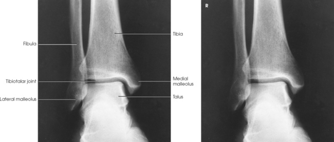
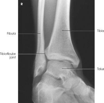
Structures shown: The image shows a true AP projection of the ankle joint, the distal ends of the tibia and fibula, and the proximal portion of the talus.
NOTE: The inferior tibiofibular articulation and the talofibular articulation are not “open” or shown in profile in the true AP projection. This is a positive sign for the radiologist because it indicates that the patient has no ruptured ligaments or other type of separations. For this reason, it is important that the position of the ankle be anatomically “true” for the AP projection shown (Fig. 6-92).
LATERAL PROJECTION
• Have the supine patient turn toward the affected side until the ankle is lateral (Fig. 6-93).
• Place the long axis of the IR parallel with the long axis of the patient’s leg, and center it to the ankle joint.
• Ensure that the lateral surface of the foot is in contact with the IR.
• Dorsiflex the foot, and adjust it in the lateral position. Dorsiflexion is required to prevent lateral rotation of the ankle.
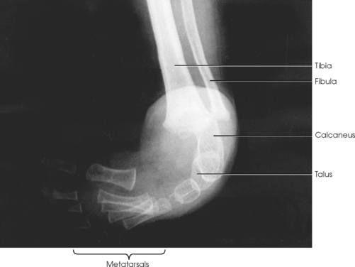
Structures shown: The resulting image shows a true lateral projection of the lower third of the tibia and fibula; the ankle joint; and the tarsals, including the base of the fifth metatarsal (Figs. 6-94 and 6-95).
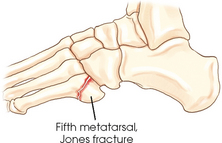
Fig. 6-94 Bones shown on lateral ankle. Including base of fifth metatarsal on lateral ankle projection can identify Jones fracture if present.
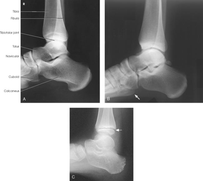
Fig. 6-95 A and B, Lateral ankle, mediolateral. Base of fifth metatarsal is seen. C, Lateral ankle of an 8-year-old child. Note tibial epiphysis (arrow).
The following should be clearly shown:
Evidence of proper collimation
Ankle joint centered to exposure area
Tibiotalar joint well visualized, with the medial and lateral talar domes superimposed
Fibula over the posterior half of the tibia
Distal tibia and fibula, talus, and adjacent tarsals
Fifth metatarsal should be seen to check for Jones fracture
Density of the ankle sufficient to see the outline of distal portion of the fibula
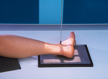
LATERAL PROJECTION
It is often recommended that the lateral projection of the ankle joint be made with the medial side of the ankle in contact with the IR. Exact positioning of the ankle is more easily and more consistently obtained when the limb is rested on its comparatively flat medial surface.
• Center the IR to the ankle joint, and adjust the IR so that its long axis is parallel with the long axis of the leg.
• Adjust the foot in the lateral position.
• Have the patient turn anteriorly or posteriorly as required to place the patella perpendicular to the horizontal plane (Fig. 6-96).
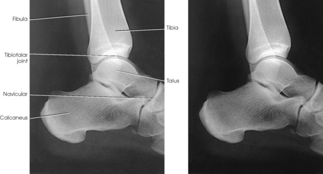
Structures shown: The resulting image shows a lateral projection of the lower third of the tibia and fibula, the ankle joint, and the tarsals (Fig. 6-97).
The following should be clearly shown:
Ankle joint centered to exposure area
Tibiotalar joint well visualized, with the medial and lateral talar domes superimposed
Fibula over the posterior half of the tibia
Distal tibia and fibula, talus, and adjacent tarsals
Density of the ankle sufficient to see the outline of distal portion of the fibula
AP OBLIQUE PROJECTION
Image receptor: 8 × 10 inch (18 × 24 cm) lengthwise or 10 × 12 inch (24 × 30 cm) crosswise for two images on one IR
• Center the IR to the ankle joint midway between the malleoli, and adjust the IR so that its long axis is parallel with the long axis of the leg.
• Dorsiflex the foot enough to place the ankle at nearly right-angle flexion (Fig. 6-98). The ankle may be immobilized with sandbags placed against the sole of the foot or by having the patient hold the ends of a strip of bandage looped around the ball of the foot.
• Rotate the patient’s leg primarily and the foot for all oblique projections of the ankle. Because the knee is a hinge joint, rotation of the leg can come only from the hip joint. Positioning the ankle for the oblique projection requires that the leg and foot be medially rotated 45 degrees.
• Grasp the lower femur area with one hand and the foot with the other. Internally rotate the entire leg and foot together until the 45-degree position is achieved.
Structures shown: The 45-degree medial oblique projection shows the distal ends of the tibia and fibula, parts of which are often superimposed over the talus. The tibiofibular articulation also should be shown (Fig. 6-99).
The following should be clearly shown:
Ankle joint centered to exposure area
Tibiotalar joint well visualized, with the medial and lateral talar domes superimposed
Fibula over the posterior half of the tibia
Distal tibia and fibula, talus, and adjacent tarsals
Density of the ankle sufficient to see the outline of distal portion of the fibula