BONY THORAX
SUMMARY OF PROJECTIONS
Bony Thorax
The bony thorax supports the walls of the pleural cavity and diaphragm used in respiration. The thorax is constructed so that the volume of the thoracic cavity can be varied during respiration. The thorax also protects the heart and lungs.
The bony thorax is formed by the sternum, 12 pairs of ribs, and 12 thoracic vertebrae. The bony thorax protects the heart and lungs. Conical in shape, the bony thorax is narrower above than below, more wide than deep, and longer posteriorly than anteriorly.
Sternum
The sternum, or breastbone, is directed anteriorly and inferiorly and is centered over the midline of the anterior thorax (Figs. 9-1 to 9-3). A narrow, flat bone about 6 inches (15 cm) in length, the sternum consists of three parts: manubrium, body, and xiphoid process. The sternum supports the clavicles at the superior manubrial angles and provides attachment to the costal cartilages of the first seven pairs of ribs at the lateral borders.
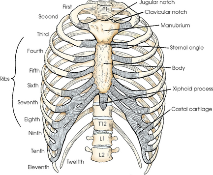
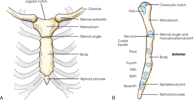
The manubrium, the superior portion of the sternum, is quadrilateral in shape and is the widest portion of the sternum. At its center, the superior border of the manubrium has an easily palpable concavity termed the jugular notch. In the upright position, the jugular notch of the average person lies anterior to the interspace between the second and third thoracic vertebrae. The manubrium slants laterally and posteriorly on each side of the jugular notch, and an oval articular facet called the clavicular notch articulates with the sternal extremity of the clavicle. On the lateral borders of the manubrium, immediately below the articular notches for the clavicles, are shallow depressions for the attachment of the cartilages of the first pair of ribs.
The body is the longest part of the sternum (4 inches [10.2 cm]) and is joined to the manubrium at the sternal angle, an obtuse angle that lies at the level of the junction of the second costal cartilage. The manubrium and the body contribute to the attachment of the second costal cartilage. The succeeding five pairs of costal cartilages are attached to the lateral borders of the body. The sternal angle is palpable; in the normally formed thorax, it lies anterior to the interspace between the fourth and fifth thoracic vertebrae when the body is upright.
The xiphoid process, the distal and smallest part of the sternum, is cartilaginous in early life and partially or completely ossifies, particularly the superior portion, in later life. The xiphoid process is variable in shape and often deviates from the midline of the body. In the normal thorax, the xiphoid process lies over the 10th thoracic vertebra and serves as a useful bony landmark for locating the superior portion of the liver and the inferior border of the heart.
Ribs
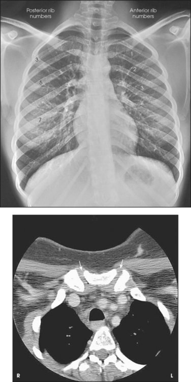
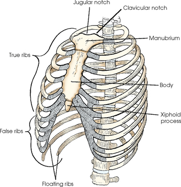
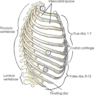
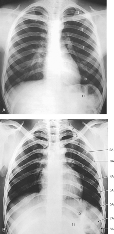
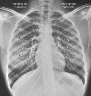
The 12 pairs of ribs are numbered consecutively from superiorly to inferiorly (Fig. 9-4; see Figs. 9-1 and 9-2). The rib number corresponds to the thoracic vertebra to which it attaches. Each rib is a long, narrow, curved bone with an anteriorly attached piece of hyaline cartilage, the costal cartilage. The costal cartilages of the first through seventh ribs attach directly to the sternum. The costal cartilages of the 8th through 10th ribs attach to the costal cartilage of the 7th rib. The ribs are situated in an oblique plane slanting anteriorly and inferiorly so that their anterior ends lie 3 to 5 inches (7.6 to 12.5 cm) below the level of their vertebral ends. The degree of obliquity gradually increases from the 1st to the 9th rib and then decreases to the 12th rib. The first seven ribs are called true ribs because they attach directly to the sternum. Ribs 8 to 12 are called false ribs because they do not attach directly to the sternum. The last two ribs (11th and 12th ribs) are often called floating ribs because they are attached only to the vertebrae. The spaces between the ribs are referred to as the intercostal spaces.
The number of ribs may be increased by the presence of cervical or lumbar ribs, or both. Cervical ribs articulate with the C7 vertebra but rarely attach to the sternum. Cervical ribs may be free or articulate or fuse with the first rib. Lumbar ribs are less common than cervical ribs. Lumbar ribs can lend confusion to images. They can confirm the identification of the vertebral level, or they can be erroneously interpreted as a fractured transverse process of the L1 vertebra.
Ribs vary in breadth and length. The first rib is the shortest and broadest; the breadth gradually decreases to the 12th rib, the narrowest rib. The length increases from the 1st to the 7th rib and then gradually decreases to the 12th rib.
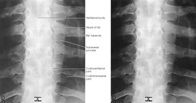
A typical rib consists of a head, a flattened neck, a tubercle, and a body (Figs. 9-5 and 9-6). The ribs have facets on their heads for articulation with the vertebrae. The facet is divided on some ribs into superior and inferior portions for articulation with demifacets on the vertebral bodies. The tubercle also contains a facet for articulation with the transverse process of the vertebra. The 11th and 12th ribs do not have a neck or tubercular facets. The two ends of a rib are termed the vertebral end and the sternal end.
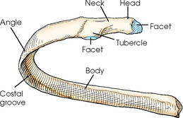
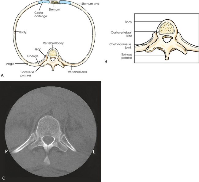
Fig. 9-6 A, Superior aspect of rib articulating with thoracic vertebra and sternum. B, Enlarged image of costovertebral and costotransverse articulations. C, MRI transverse image showing costovertebral and costotransverse articulations. (C, From Kelley LL, Petersen CM: Sectional anatomy for imaging professionals, ed 2, St Louis, 2007, Mosby.)
From the point of articulation with the vertebral body, the rib projects posteriorly at an oblique angle to the point of articulation with the transverse process. The rib turns laterally to the angle of the body, where the bone arches anteriorly, medially, and inferiorly in an oblique plane. Located along the inferior and internal border of each rib is the costal groove, which contains costal arteries, veins, and nerves. Trauma to the ribs can damage these neurovascular structures, causing pain and hemorrhage.
Bony Thorax Articulations
The eight joints of the bony thorax are summarized in Table 9-1. A detailed description follows.
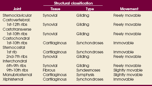
The sternoclavicular joints are the only points of articulation between the upper limbs and the trunk (see Fig. 9-3). Formed by the articulation between the sternal extremity of the clavicles and the clavicular notches of the manubrium, these synovial gliding joints permit free movement (the gliding of one surface on the other). A circular disk of fibrocartilage is interposed between the articular ends of the bones in each joint, and the joints are enclosed in articular capsules.
Posteriorly, the head of a rib is closely bound to the demifacets of two adjacent vertebral bodies to form a synovial gliding articulation called the costovertebral joint (Fig. 9-7, A; see Fig. 9-6). The 1st, 10th, 11th, and 12th ribs each articulate with only one vertebral body.
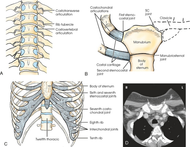
Fig. 9-7 Rib articulations. A, Anterior aspect of thoracic spine, showing costovertebral articulations. B, Anterior aspect of manubrium, sternum, and first two ribs, showing articulations. SC, sternoclavicular. C, Lower sternum and ribs, showing intercostal, costochondral, and sternocostal joints. D, CT cross-section image of upper thorax showing manubrium and angulation of sternoclavicular joints (arrows).
The tubercle of a rib articulates with the anterior surface of the transverse process of the lower vertebra at the costotransverse joint, and the head of the rib articulates at the costovertebral joint. The head of the rib also articulates with the body of the same vertebra and articulates with the vertebra directly above. The costotransverse articulation is also a synovial gliding articulation. The articulations between the tubercles of the ribs and the transverse processes of the vertebrae permit only superior and inferior movements of the first six pairs. Greater freedom of movement is permitted in the succeeding four pairs.
Costochondral articulations are found between the anterior extremities of the ribs and the costal cartilages (see Fig. 9-7, B). These articulations are cartilaginous synchondroses and allow no movement. The articulations between the costal cartilages of the true ribs and the sternum are called sternocostal joints. The first pair of ribs, rigidly attached to the sternum, form the first sternocostal joint. This is a cartilaginous synchondrosis type of joint, which allows no movement. The second through seventh sternocostal joints are considered synovial gliding joints and are freely movable. Interchondral joints are found between the costal cartilages of the sixth and seventh, seventh and eighth, and eighth and ninth ribs (see Fig. 9-7, C). These interchondral joints are synovial gliding articulations. The interchondral articulation between the 9th and 10th ribs is a fibrous syndesmosis and is only slightly movable.
The manubriosternal joint is a cartilaginous symphysis joint, and the xiphisternal joints are cartilaginous synchondrosis joints that allow little or no movement (see Figs. 9-3, B, and 9-7, B and C).
RESPIRATORY MOVEMENT
The normal oblique orientation of the ribs changes little during quiet respiratory movements; however, the degree of obliquity decreases with deep inspiration and increases with deep expiration. The first pair of ribs, which are rigidly attached to the manubrium, rotate at their vertebral ends and move with the sternum as one structure during respiratory movements.
On deep inspiration, the anterior ends of the ribs are carried anteriorly, superiorly, and laterally while the necks are rotated inferiorly (Fig. 9-8, A). On deep expiration, the anterior ends are carried inferiorly, posteriorly, and medially, while the necks are rotated superiorly (Fig. 9-8, B). The last two pairs of ribs are depressed and held in position by the action of the diaphragm when the anterior ends of the upper ribs are elevated during respiration.
DIAPHRAGM
The ribs located above the diaphragm are best examined radiographically through the air-filled lungs, whereas the ribs situated below the diaphragm must be examined through the upper abdomen. Because of the difference in penetration required for the two regions, the position and respiratory excursion of the diaphragm play a large role in radiography of the ribs.
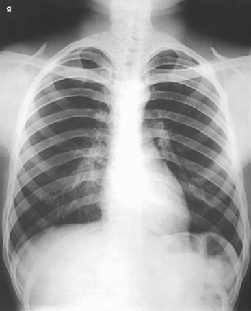
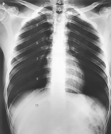
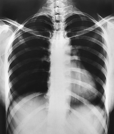
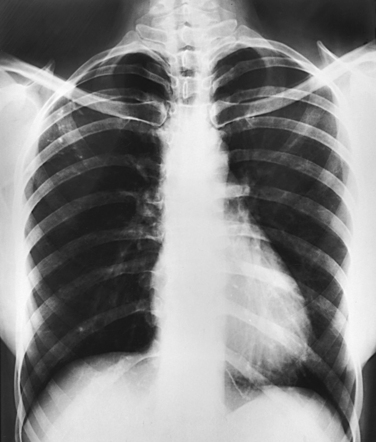
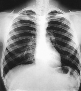
The position of the diaphragm varies with body habitus: It is at a higher level in hypersthenic patients and at a lower level in asthenic patients (Fig. 9-9). In sthenic patients of average size and shape, the right side of the diaphragm arches posteriorly from the level of about the 6th or 7th costal cartilage to the level of the 9th or 10th thoracic vertebra when the body is in the upright position. The left side of the diaphragm lies at a slightly lower level. Because of the oblique location of the ribs and the diaphragm, several pairs of ribs appear on radiographs to lie partly above and partly below the diaphragm.
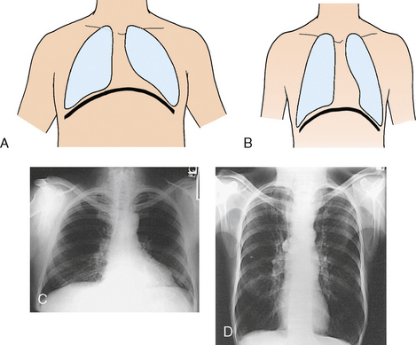
Fig. 9-9 Diaphragm position and body habitus. A, A hypersthenic patient has a diaphragm positioned higher. B, An asthenic patient has a diaphragm positioned lower. C, Chest radiograph of a hypersthenic patient. D, Chest radiograph of an asthenic patient. Note position of diaphragm on these extremely different body types.
The position of the diaphragm changes considerably with the body position, reaching its lowest level when the body is upright and its highest level when the body is supine. For this reason, it is desirable to place the patient in the upright position for examination of the ribs above the diaphragm and in a recumbent position for examination of the ribs below the diaphragm.
The respiratory movement of the diaphragm averages about 1½ inches (3.8 cm) between deep inspiration and deep expiration. The movement is less in hypersthenic patients and more in hyposthenic patients. Deeper inspiration or expiration and greater depression or elevation of the diaphragm are achieved on the second respiratory movement than on the first. This greater movement should be taken into consideration when the ribs that lie at the diaphragmatic level are examined.
When the body is placed in the supine position, the anterior ends of the ribs are displaced superiorly, laterally, and posteriorly. For this reason, the anterior ends of the ribs are less sharply visualized when the patient is radiographed in the supine position.
BODY POSITION
Although in rib examinations it is desirable to take advantage of the effect that body position has on the position of the diaphragm, the effect is not of sufficient importance to justify subjecting a patient to a painful change from the upright position to the recumbent position or vice versa. Even minor rib injuries are painful, and slight movement frequently causes the patient considerable distress. Unless the change in position can be effected with a tilting radiographic table, patients with recent rib injury should be examined in the position in which they arrive in the radiology department. An ambulatory patient can be positioned for recumbent images with minimal discomfort by bringing the tilt table to the vertical position for each positioning change. The patient stands on the footboard, is comfortably adjusted, and is then lowered to the horizontal position.
TRAUMA PATIENTS
The first and usually the only requirement in the initial radiographic examination of a patient who has sustained severe trauma to the rib cage is to take AP and lateral projections of the chest. These projections are obtained not only to show the site and extent of rib injury, but also to investigate the possibility of injury to the underlying structures by depressed rib fractures. Patients are examined in the position in which they arrive, usually recumbent on a stretcher. The recumbent position is necessary to show the presence of air or fluid levels using the decubitus technique.
SUMMARY OF PATHOLOGY
| Condition | Definition |
| Fracture | Disruption of the continuity of bone |
| Metastases | Transfer of a cancerous lesion from one area to another |
| Osteomyelitis | Inflammation of bone owing to a pyogenic infection |
| Osteopetrosis | Increased density of atypically soft bone |
| Osteoporosis | Loss of bone density |
| Paget disease | Thick, soft bone marked by bowing and fractures |
| Tumor | New tissue growth where cell proliferation is uncontrolled |
| Chondrosarcoma | Malignant tumor arising from cartilage cells |
| Multiple myeloma | Malignant neoplasm of plasma cells involving the bone marrow and causing destruction of bone |
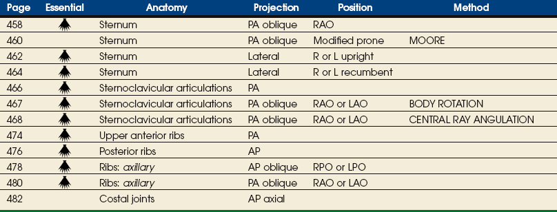
EXPOSURE TECHNIQUE CHART ESSENTIAL PROJECTIONS
Sternum
The position of the sternum with respect to the denser bony and soft tissue thoracic structures makes it a difficult structure to radiograph satisfactorily. Few problems are involved in obtaining a lateral projection, but because of the location of the sternum directly anterior to the thoracic spine, an AP or PA projection provides little useful diagnostic information. To separate the vertebrae and sternum, it is necessary to rotate the body from the prone position or to angle the central ray medially. The exact degree of required angulation depends on the depth of the chest, with deep chests requiring less angulation than shallow chests (Fig. 9-10 and Table 9-2).
TABLE 9-2
Sternum: thickness and central ray angulation
| Depth of thorax (cm) | Depth of tube angulation |
| 15 | 22 |
| 16.5 | 21 |
| 18 | 20 |
| 19.5 | 19 |
| 21 | 18 |
| 22.5 | 17 |
| 24 | 16 |
| 25.5 | 15 |
| 27 | 14 |
| 28.5 | 13 |
| 30 | 12 |

Angulation of the body or the central ray to project the sternum to the right of the thoracic vertebrae clears the sternum of the vertebrae but superimposes it over the posterior ribs and the lung markings (Fig. 9-11). If the sternum is projected to the left of the thoracic vertebrae, it is also projected over the heart and other mediastinal structures (Fig. 9-12). The super imposition of the homogeneous density of the heart can be used to advantage (compare Figs. 9-11 and 9-12).
The pulmonary structures, particularly in elderly persons and heavy smokers, can cast confusing markings over the sternum, unless the motion of shallow breathing is used to eliminate them. If motion is desired, the exposure time should be long enough to cover several phases of shallow respiration (Figs. 9-13 and 9-14). The milliampere (mA) must be relatively low to achieve the desired milliampere-second (mAs).
If a female patient has large, pendulous breasts, they should be drawn to the sides and held in position with a wide bandage to prevent them from overlapping the sternum and to position the sternum closer to the image receptor (IR). This positioning is particularly important in the lateral projection, in which the breast can obscure the inferior portion of the sternum.
Radiation Protection
Protection of the patient from unnecessary radiation is a professional responsibility of the radiographer (see Chapter 1 for specific guidelines). In this chapter, the Shield gonads statement indicates that the patient is to be protected from unnecessary radiation by restricting the radiation beam using proper collimation. In addition, the placement of lead shielding between the gonads and the radiation source is appropriate when the clinical objectives of the examination are not compromised.
 PA OBLIQUE PROJECTION
NOTE: This position may be difficult to perform on trauma patients. Use an upright position if necessary or possible.
SID: A 30-inch (76-cm) source-to-IR distance (SID) is recommended to blur the posterior ribs. See page 31, Chapter 1, for use of a 30-inch (76-cm) SID.
• Adjust the elevation of the left shoulder and hip so that the thorax is rotated just enough to prevent superimposition of the vertebrae and sternum.
• Estimate the amount of rotation with sufficient accuracy by placing one hand on the patient’s sternum and the other hand on the thoracic vertebrae to act as guides while adjusting the degree of obliquity. The average rotation is about 15 to 20 degrees (Fig. 9-15).
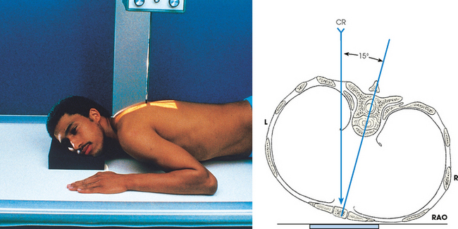
Fig. 9-15 PA oblique sternum, RAO position. Line drawing is an axial view (from feet upward). CR, central ray.
• Align the patient’s body so that the long axis of the sternum is centered to the midline of the grid.
• Place the top of the IR about 1½ inches (3.8 cm) above the jugular notch.
• Respiration: When breathing motion is to be used, instruct the patient to take slow, shallow breaths during the exposure. When a short exposure time is to be used, instruct the patient to suspend breathing at the end of expiration to obtain a more uniform density.
NOTE: On trauma patients, obtain this projection with the patient supine, and use the LPO position and AP oblique projection.
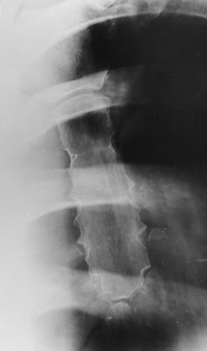
Structures shown: This image shows a slightly oblique projection of the sternum (Fig. 9-16). The detail depends largely on the technical procedure employed. If breathing motion is used, the pulmonary markings are obliterated.
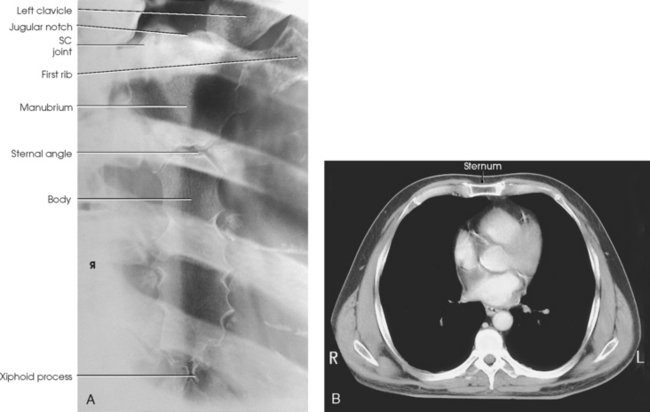
Fig. 9-16 A, PA oblique sternum, RAO position. SC, sternoclavicular. B, CT is often used today to image the sternum. Image shows sternum in axial plane. (B, Modified from Kelley LL, Petersen CM: Sectional anatomy for imaging professionals, ed 2, St Louis, 2007, Mosby.)
The following should be clearly shown:
 Evidence of proper collimation
Entire sternum from jugular notch to tip of xiphoid process
Reasonably good visibility of the sternum through the thorax, including blurred pulmonary markings if a breathing technique was used
Minimally rotated sternum and thorax, as shown by the following:

PA OBLIQUE PROJECTION
Modified prone position
SID: A 30-inch (76-cm) SID is recommended. This short distance assists in blurring the posterior ribs.
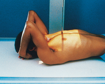
Radiography of the sternum can be difficult to perform on an ambulatory patient who is having acute pain. The alternative positioning method described by Moore1 employs a modified prone position that makes it possible to produce a highquality sternum image in a more comfortable manner for the patient.
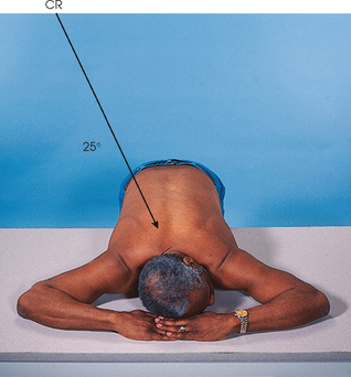
• Before positioning the patient, place the IR crosswise in the Bucky tray. Place the x-ray tube at a 30-inch (76-cm) SID, angle it 25 degrees, and direct the central ray to the center of the IR. The x-ray tube is positioned over the patient’s right side.
• Place a marker on the tabletop near the patient’s head to indicate the exact center of the IR.
• Have the patient stand at the side of the radiographic table directly in front of the Bucky tray.
• Ask the patient to bend at the waist, and place the sternum in the center of the table directly over the previously positioned IR.
• Place the patient’s arms above the shoulders and the palms down on the table. The arms act as a support for the side of the head (Fig. 9-17).
• Ensure that the patient is in a true prone position and that the mid-sternal area is at the center of the radiographic table.
• Respiration: A shallow breathing technique produces the best results. Instruct the patient to take slow, shallow breaths during the exposure. A low mA setting and an exposure time of 1 to 3 seconds is recommended. When a low mA setting and long exposure time cannot be employed, instruct the patient to suspend respiration at the end of expiration to obtain a more uniform density.
• The central ray is already angled 25 degrees and centered to the IR. If patient positioning is accurate, the central ray enters at the level of T7 and approximately 2 inches (5 cm) to the right of the spine. This angulation places the sternum over the lung to maintain maximum contrast of the sternum.
• The x-ray tube angulation can be adjusted for extremely large or small patients. Large patients require less angulation, and thin patients require more angulation than the standard 25-degree angle.
Structures shown: This image shows a slightly oblique projection of the sternum (Fig. 9-18). The degree of detail shown depends largely on the technique used. If a breathing technique is used, the pulmonary markings are obliterated.
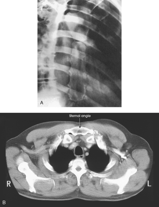
Fig. 9-18 A, PA oblique projection: Moore method. B, CT image shows sternal angle in axial plane. (B, Modified from Kelley LL, Petersen CM: Sectional anatomy for imaging professionals, ed 2, St Louis, 2007, Mosby.)
The following should be clearly shown:
Entire sternum from the jugular notch to the tip of the xiphoid process
Reasonably good visibility of the sternum through the thorax
Blurred pulmonary markings if a breathing technique was used
Blurred posterior ribs if a reduced SID was used
Sternum projected free of superimposition from the vertebral column
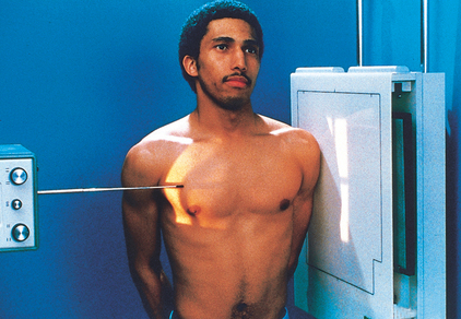
LATERAL PROJECTION
• Have the patient sit or stand straight.
• Rotate the shoulders posteriorly, and have the patient lock the hands behind the back.
• Center the sternum to the midline of the grid.
• Being careful to keep the midsagittal plane of the body vertical, place the patient close enough to the grid so that the shoulder can be rested firmly against it.
• Adjust the patient in a true lateral position so that the broad surface of the sternum is perpendicular to the plane of the IR (Fig. 9-19).
• Large breasts on female patients should be drawn to the sides and held in position with a wide bandage so that their shadows do not obscure the lower portion of the sternum.
• Adjust the height of the IR so that its upper border is 1½ inches (3.8 cm) above the jugular notch.
• For a direct lateral projection of just the sternoclavicular region, center vertically placed 8 × 10 inch (18 × 24 cm) IR at the level of the jugular notch.
• Respiration: Suspended deep inspiration. This provides sharper contrast between the posterior surface of the sternum and the adjacent structures.
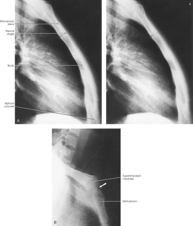
Structures shown: A lateral image of the entire length of the sternum shows the superimposed sternoclavicular joints and medial ends of the clavicles (Fig. 9-20, A). A lateral projection of only the sternoclavicular region is shown in Fig. 9-20, B.
LATERAL PROJECTION
SID: A 72-inch (180-cm) SID is preferred. If this distance cannot be obtained with the overhead tube, the maximum allowed distance should be obtained.
• Extend the patient’s arms over the head to prevent them from overlapping the sternum.
• Rest the patient’s head on the arms or on a pillow (Fig. 9-21, A).
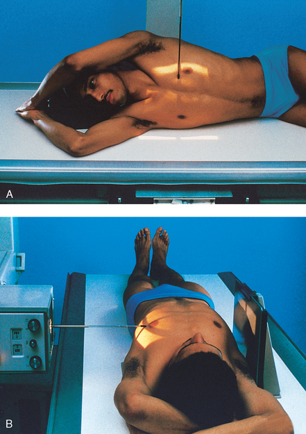
• Place a support under the lower thoracic region to position the long axis of the sternum horizontally.
• Adjust the rotation of the patient’s body so that the broad surface of the sternum is perpendicular to the plane of the IR.
• Center the sternum to the midline of the grid.
• Apply a compression band across the hips for immobilization, if necessary.
• Adjust the height of the IR so that its upper border is 1½ inches (3.8 cm) above the jugular notch.
• Respiration: Suspend at the end of deep inspiration to obtain high contrast between the posterior surface of the sternum and the adjacent structures.
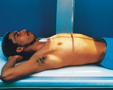
NOTE: Use the dorsal decubitus position for examination of a patient with severe injury. In this situation, a grid-front IR or stationary grid should be used (Fig. 9-21, B). SID of 72 inches (180 cm) can be used for this position.
Structures shown: The lateral aspect of the entire length of the sternum is shown (Fig. 9-22).
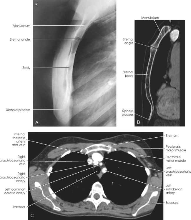
Fig. 9-22 A, Lateral sternum. B, Sagittal CT reformat of sternum. C, Axial CT scan of chest showing sternum in relation to surrounding organs. (B and C, From Kelley LL, Petersen CM: Sectional anatomy for imaging professionals, ed 2, St Louis, 2007, Mosby.)
The following should be clearly shown:
Evidence of proper collimation
Lateral image of the sternum in its entirety
Sternum free of superimposition by the soft tissues of the shoulders or arms
Sternum free of superimposition by the ribs
Inferior portion of the sternum unobscured by the breasts of a female patient (a second radiograph with increased penetration may be necessary)
Sternoclavicular Articulations
NOTE: This position may be difficult to perform on trauma patients. Use the upright position if the patient is able.
• Center the IR at the level of the spinous process of the third thoracic vertebra, which lies posterior to the jugular notch.
• Place the patient’s arms along the sides of the body with the palms facing upward.
• Adjust the shoulders to lie in the same transverse plane.
• For a bilateral examination, rest the patient’s head on the chin and adjust it so that the midsagittal plane is vertical.
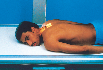
• For a unilateral projection, ask the patient to turn the head to face the affected side and rest the cheek on the table (Fig. 9-23). Turning the head rotates the spine slightly away from the side being examined and provides better visualization of the lateral portion of the manubrium.
• Respiration: Suspend at the end of expiration to obtain a more uniform density.
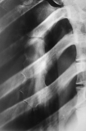
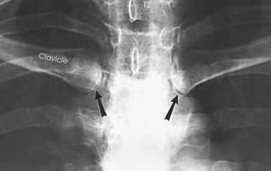
Structures shown: A PA projection shows the sternoclavicular joints and the medial portions of the clavicles (Figs. 9-24 and 9-25).
PA OBLIQUE PROJECTION
RAO or LAO position
NOTE: This position may be difficult in trauma patients. Use the upright position if the patient is able.
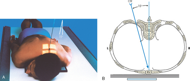
• Keeping the affected side adjacent to the IR, position the patient at enough of an oblique angle to project the vertebrae well behind the sternoclavicular joint closest to the IR. The angle is usually about 10 to 15 degrees.
• Adjust the patient’s position to center the joint to the midline of the grid.
• Adjust the shoulders to lie in the same transverse plane (Fig. 9-26, A and B).
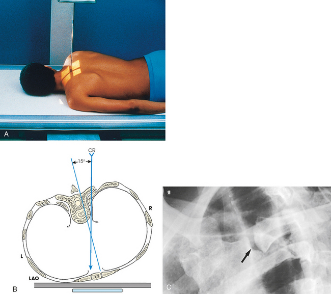
Fig. 9-26 A, PA oblique sternoclavicular joint, LAO position: Body rotation method. B, Axial view (from feet upward) of central ray position in relation to spine and sternoclavicular joint. C, PA oblique sternoclavicular joint, LAO position. The joint closest to IR is shown (arrow). CR, central ray.
• Respiration: Suspend at the end of expiration to obtain a more uniform density.
• Perpendicular to the sternoclavicular joint closest to the IR. The central ray enters at the level of T2-3 (about 3 inches [7.6 cm] distal to the vertebral prominens) and 1 to 2 inches (2.5 to 5 cm) lateral from the midsagittal plane. If the central ray enters the right side, the left sternoclavicular joint is shown, and vice versa (see Fig. 9-26, B).
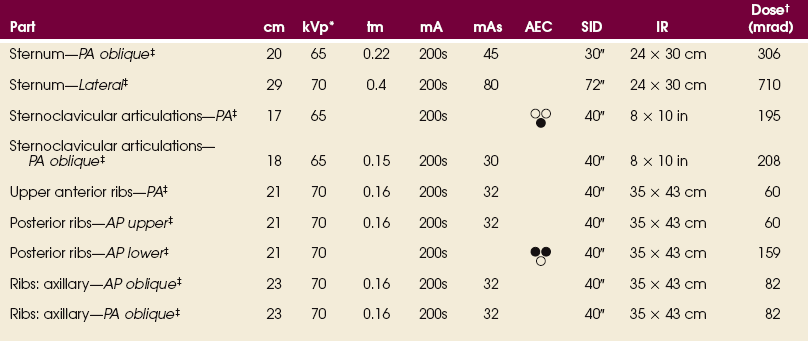
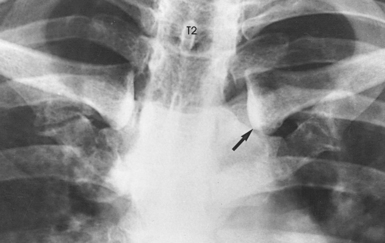
Structures shown: A slightly oblique image of the sternoclavicular joint is shown (see Fig. 9-26, C).
The following should be clearly shown:
Evidence of proper collimation
Sternoclavicular joint of interest in the center of the radiograph, with the manubrium and the medial end of the clavicle included
Open sternoclavicular joint space
Sternoclavicular joint of interest immediately adjacent to the vertebral column with minimal obliquity
Reasonably good visibility of the sternoclavicular joint through the superimposing rib and lung fields
PA OBLIQUE PROJECTION
Non-Bucky
NOTE: For this projection, the joint is closer to the IR, and less distortion is obtained than when the previously described body rotation method is used. A grid IR placed on the tabletop also enables the joint to be projected with minimal distortion. Also, this position may be difficult to perform on trauma patients. Use the upright position if the patient is able.
• Extend the patient’s arms along the sides of the body with the palms of the hands facing upward.
• Adjust the shoulders to lie in the same transverse plane.
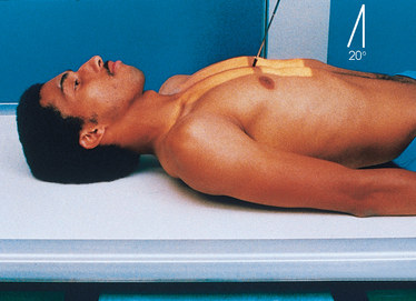
• Ask the patient to rest the head on the chin or to rotate the chin toward the side of the joint being radiographed (Fig. 9-27).
• From the side opposite that is being examined, direct to the midpoint of the IR at an angle of 15 degrees toward the midsagittal plane. A small angle is satisfactory in examinations of sternoclavicular articulations because only a slight anteroposterior overlapping of the vertebrae and these joints occurs.
• The central ray should enter at the level of T2-3 (about 3 inches [7.6 cm] distal to the vertebral prominens) and 1 to 2 inches (2.5 to 5 cm) lateral to the midsagittal plane. If the central ray enters the left side, the right side is shown and vice versa.
Structures shown: A slightly oblique image of the sternoclavicular joint is shown (Figs. 9-28 and 9-29).

Fig. 9-28 CT axial image with patient prone, showing sternoclavicular joints (white arrows) and path of central ray (CR). View is from feet looking upward.
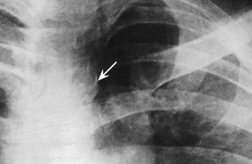
Fig. 9-29 Central ray angulation method for sternoclavicular joint farthest from x-ray tube (arrow). (From Kurzbauer R: The lateral projection in the roentgenography of the sternoclavicular articulation, AJR Am J Roentgenol 56:104, 1946.)
The following should be clearly shown:
Evidence of proper collimation
Sternoclavicular joint of interest in the center of the radiograph, with the manubrium and the medial end of the clavicle included
Open sternoclavicular joint space
Sternoclavicular joint of interest immediately adjacent to the vertebral column with minimal obliquity
Reasonably good visibility of the sternoclavicular joint through the superimposing rib and lung fields
Ribs
In radiography of the ribs, an IR 14 × 17 inches (35 × 43 cm) should be used to identify the ribs involved and to determine the extent of trauma or pathologic condition. An IR 11 × 14 inches (28 × 36 cm) is often used with smaller patients. Projections can be made in recumbent and upright positions. If the area in question involves the first and last ribs, additional images may be required to show the affected area better (Fig. 9-30).
After the lesion is localized, the next step is to determine (1) the position required to place the affected rib region parallel with the plane of the IR and (2) whether the radiograph should be made to include the ribs above or below the diaphragm.
The anterior portion of the ribs, usually referred to simply as the anterior ribs, is often examined with the patient facing the IR for a PA projection (Fig. 9-31). The posterior portion of the ribs, or the posterior ribs, is more commonly radiographed with the patient facing the x-ray tube in the same manner as for an AP projection (Fig. 9-32).
The axillary portion of the ribs is best shown using an oblique projection. Because the lateral projection results in superimposition of the two sides, it is generally used only when fluid or air levels are evaluated after rib fractures.
When the ribs superimposed over the heart are involved, the body must be rotated to obtain a projection of the ribs free of the heart, or the radiographic exposure must be increased to compensate for the density of the heart. Although the anterior and posterior ends are superimposed, the left ribs are cleared of the heart when the LAO position (Fig. 9-33) or RPO position (Fig. 9-34) is used. These two body positions place the right-sided ribs parallel with the plane of the IR and are reversed to obtain comparable projections of the left-sided ribs. Technical factors that result in a short-scale radiograph are often used (about 70 kVp).
RESPIRATION
In radiography of the ribs, the patient is usually examined with respiration suspended in either full inspiration or expiration. Occasionally, shallow breathing may be used to obliterate lung markings. If this technique is used, breathing must be shallow enough to ensure that the ribs are not elevated or depressed as described in the anatomy portion of this chapter. Examples of shallow breathing and suspended respiration are compared in Figs. 9-35 and 9-36.
Rib fractures can cause a great deal of pain and hemorrhage because of the closely related neurovascular structures. This situation commonly makes it difficult for the patient to breathe deeply for the required radiograph. Deeper inspiration is attained if the patient fully understands the importance of expanding the lungs and if the exposure is made after the patient takes the second deep breath.
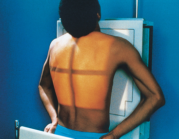
Upper Anterior Ribs
• Position the patient either upright or recumbent for a PA projection.
• Because the diaphragm descends to its lowest level in the upright position, use the standing or seated-upright position for projections of the upper ribs when the patient’s condition permits (Fig. 9-37). The upright position is also valuable for showing fluid levels in the chest.
• Center the midsagittal plane of the patient’s body to the midline of the grid.
• To include the upper ribs, adjust the IR position to project approximately 1½ inches (3.8 cm) above the upper border of the shoulders.
• Rest the patient’s hands against the hips with the palms turned outward to rotate the scapulae away from the rib cage.
• Adjust the shoulders to lie in the same transverse plane.
• If the patient is prone, rest the head on the chin and adjust the midsagittal plane to be vertical (Fig. 9-38).
• To image affected ribs unilaterally, use 11 × 14 inch (28 × 35 cm) collimator size for contrast improvement.
• For hypersthenic patients with wide rib cages, include the entire lateral surface of the affected rib area on the radiograph. This may require moving the patient laterally to include all of the affected ribs.
• Respiration: Suspend at full inspiration to depress the diaphragm as much as possible.
• Perpendicular to the center of IR. If the IR is positioned correctly, the central ray is at the level of T7.
• A useful option for showing the seventh, eighth, and ninth ribs is to angle the x-ray tube about 10 to 15 degrees caudad. This angulation aids in projecting the diaphragm below that of the affected ribs.
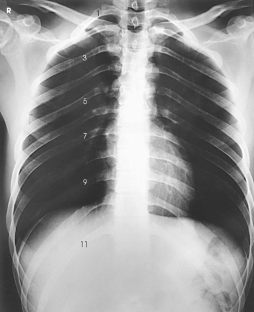
Structures shown: PA projection best shows the anterior ribs above the diaphragm (Figs. 9-39 and 9-40). The posterior ribs are seen. The anterior ribs are shown with greater detail, however, because they lie closer to the IR.
The following should be clearly shown:
Evidence of proper collimation
First through ninth ribs in their entirety, with the posterior portions lying above the diaphragm
First through seventh anterior ribs from both sides, in their entirety and above the diaphragm
In a unilateral examination, ribs from the opposite side possibly not included in their entirety.
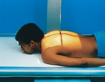
Posterior Ribs
• Have the patient face the x-ray tube in either an upright or a recumbent position.
• When the patient’s condition permits, use the upright position to image ribs above the diaphragm and the supine position to image ribs below the diaphragm to permit gravity to assist in moving the patient’s diaphragm.
• Place the IR lengthwise 1½ inches (3.8 cm) above the upper border of the relaxed shoulders.
• Rest the patient’s hands, palms outward, against the hips. This position moves the scapula off the ribs. Alternatively, extend the arms to the vertical position with the hands under the head (Fig. 9-41).
• Adjust the patient’s shoulders to lie in the same transverse plane, and rotate them forward to draw the scapulae away from the rib cage.
• Respiration: Suspend at full inspiration to depress the diaphragm.
• Place the IR crosswise in the Bucky tray with the lower edge positioned at the level of the iliac crests. This positioning ensures inclusion of the lower ribs because of the divergent x-rays.
• Adjust the patient’s shoulders to lie in the same transverse plane.
• Place the patient’s arms in a comfortable position (Fig. 9-42).
• Respiration: Suspend at full expiration to elevate the diaphragm.
NOTE: Refer to the Exposure Technique Chart on p. 455 for the different exposure settings for the upper and lower rib projections.
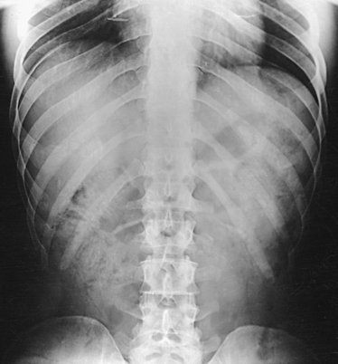
Structures shown: AP projection best shows the posterior ribs above or below the diaphragm, according to the region examined (Figs. 9-43 and 9-44). The anterior ribs are seen. The posterior ribs are shown with greater detail, however, because they lie closer to the IR.
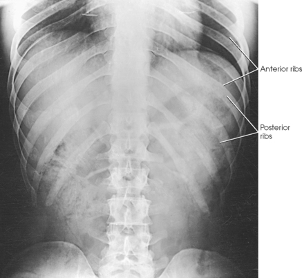
The following should be clearly shown:
Evidence of proper collimation
For ribs above the diaphragm, 1st through 10th posterior ribs from both sides in their entirety
For ribs below the diaphragm, 8th through 12th posterior ribs on both sides in their entirety
Ribs visible through the lungs or abdomen
In a unilateral examination, ribs from the opposite side possibly not included in their entirety
Axillary
RPO or LPO position
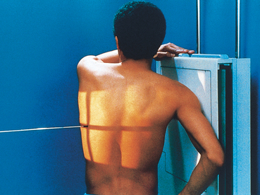
• Position the patient’s body for a 45-degree AP oblique projection using the RPO or LPO position. Place the affected side closest to the IR.
• Center the affected side on a longitudinal plane drawn midway between the midsagittal plane and the lateral surface of the body.
• Position this plane to the midline of the grid.
• If the patient is in the recumbent position, support the elevated hip.
• Abduct the arm of the affected side, and elevate it to carry the scapula away from the rib cage.
• Rest the patient’s hand on the head if the upright position is used (Fig. 9-45), or place the hand under or above the head if the recumbent position is used (Fig. 9-46).


• Abduct the opposite limb with the hand on the hip.
• Center the IR with the top 1½ inches (3.8 cm) above the upper border of the relaxed shoulder to image ribs above the diaphragm or with the lower edge of the IR at the level of the iliac crest to image ribs below the diaphragm.
• Respiration: Suspend at the end of deep expiration for ribs below the diaphragm and at the end of full inspiration for ribs above the diaphragm.
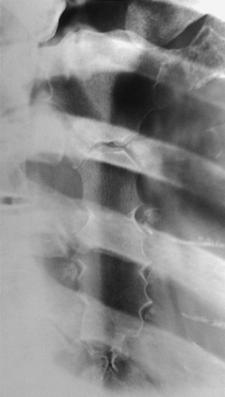
Structures shown: In these images, the axillary portion of the ribs closest to the IR are projected free of superimposition (Fig. 9-47). The posterior ribs closest to the IR are also well shown.
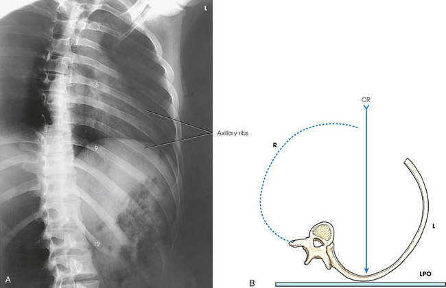
Fig. 9-47 A, AP oblique ribs. LPO position shows left-side ribs. B, Axial view (from feet upward) of ribs and central ray (CR), LPO position.
The following should be clearly shown:
Evidence of proper collimation
Approximately twice as much distance between the vertebral column and the lateral border of the ribs on the affected side as is present on the unaffected side
Axillary portion of the ribs free of superimposition
First through 10th ribs visible above the diaphragm for upper ribs
Eighth through 12th ribs visible below the diaphragm for lower ribs
Ribs visible through the lungs or abdomen according to region examined
Axillary
RAO or LAO position
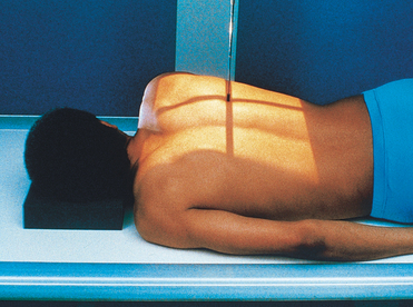
• Position the body for a 45-degree PA oblique projection using the RAO or LAO position. Place the affected side away from the IR (Fig. 9-48).
• If the recumbent position is used, have the patient rest on the forearm and flexed knee of the elevated side (Fig. 9-49).
• Align the body so that a longitudinal plane drawn midway between the midline and the lateral surface of the body side up is centered to the midline of the grid.
• Center IR with the top 1½ inches (3.8 cm) above the upper border of the shoulder to image ribs above the diaphragm or with the lower edge of IR at the level of the iliac crest to image ribs below the diaphragm.
• Respiration: Suspend at the end of full expiration for ribs below the diaphragm and at the end of full inspiration for ribs above the diaphragm.
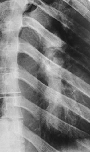
Structures shown: In these images, the axillary portion of the ribs farthest from the IR is projected free of bony superimposition (Fig. 9-50). The anterior ribs farthest from the IR are also shown.
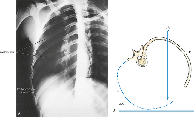
Fig. 9-50 A, PA oblique ribs. LAO position shows right-side ribs. PA projection radiograph is placed in the anatomic position for display. B, Axial view (from feet upward) of ribs and central ray (CR) with the patient in LAO position.
The following should be clearly shown:
Evidence of proper collimation
Approximately twice as much distance between the vertebral column and the lateral border of the ribs on the affected side as is present on the unaffected side
Axillary portion of the ribs free of superimposition
First through 10th ribs visible above the diaphragm for upper ribs
Eighth through 12th ribs visible below the diaphragm for lower ribs
Ribs visible through the lungs or abdomen according to the region examined
Costal Joints
This projection is recommended to show the costal joints in patients with rheumatoid spondylitis.
• Center the midsagittal plane to the midline of the grid.
• If the patient has pronounced dorsal kyphosis, extend the arms over the head; otherwise, place the arms along the sides of the body.
• Adjust the patient’s shoulders to lie in the same transverse plane (Fig. 9-51).
• With the IR in the Bucky tray, adjust its position so that the midpoint of the IR coincides with the central ray.
• Apply compression across the thorax, if necessary.
• Respiration: Suspend at the end of full inspiration because the lung markings are less prominent at this phase of breathing.
1Moore TF: An alternative to the standard radiographic position for the sternum, Radiol Technol 60:133, 1988.