PRELIMINARY STEPS IN RADIOGRAPHY
Ethics in radiologic technology
Diagnosis and the radiographer
Care of the radiographic examining room
Centers for Disease Control and Prevention
Minor surgical procedures in the radiology department
Patient’s attire, ornaments, and surgical dressings
English-metric conversion and film sizes
Source–to–image receptor distance
Foundation exposure techniques and charts
Adaptation of exposure technique to patients
Ethics in Radiologic Technology
Ethics is the term applied to a health professional’s moral responsibility and the science of appropriate conduct toward others. The work of the medical professional requires strict rules of conduct. The physician, who is responsible for the welfare of the patient, depends on the absolute honesty and integrity of all health care professionals to carry out orders and report mistakes.
The American Society of Radiologic Technologists (ASRT) developed the current code of ethics.1 The Canadian Association of Medical Radiation Technologists (CAMRT) has adopted a similar code of ethics.2 All radiographers should familiarize themselves with these codes.
AMERICAN SOCIETY OF RADIOLOGIC TECHNOLOGISTS CODE OF ETHICS
1. The radiologic technologist conducts himself or herself in a professional manner, responds to patient needs, and supports colleagues and associates in providing quality patient care.
2. The radiologic technologist acts to advance the principal objective of the profession to provide services to humanity with full respect for the dignity of humankind.
3. The radiologic technologist delivers patient care and service unrestricted by concerns of personal attributes or the nature of the disease or illness, and without discrimination, regardless of gender, race, creed, religion, or socioeconomic status.
4. The radiologic technologist practices technology founded on theoretic knowledge and concepts, uses equipment and accessories consistent with the purpose for which they have been designed, and employs procedures and techniques appropriately.
5. The radiologic technologist assesses situations; exercises care, discretion, and judgment; assumes responsibility for professional decisions; and acts in the best interest of the patient.
6. The radiologic technologist acts as an agent through observation and communication to obtain pertinent information for the physician to aid in the diagnosis and treatment management of the patient. He or she recognizes that interpretation and diagnosis are outside the scope of practice for the profession.
7. The radiologic technologist uses equipment and accessories; employs techniques and procedures; performs services in accordance with an accepted standard of practice; and demonstrates expertise in minimizing radiation exposure to the patient, self, and other members of the health care team.
8. The radiologic technologist practices ethical conduct appropriate to the profession and protects the patient’s right to quality radiologic technology care.
9. The radiologic technologist respects confidence entrusted in the course of professional practice, respects the patient’s right to privacy, and reveals confidential information only as required by law or to protect the welfare of the individual or the community.
10. The radiologic technologist continually strives to improve knowledge and skills by participating in educational and professional activities, sharing knowledge with colleagues, and investigating new and innovative aspects of professional practice.
CANADIAN ASSOCIATION OF MEDICAL RADIATION TECHNOLOGISTS CODE OF ETHICS
The CAMRT recognizes its obligation to identify and promote professional standards of conduct and performance. The execution of such standards is the personal responsibility of each member.
The code of ethics, adopted in June 1991, requires all members to do the following:
• Provide service with dignity and respect to all people regardless of race, national or ethnic origin, color, gender, religion, age, type of illness, and mental or physical challenges.
• Encourage the trust and confidence of the public through high standards of professional competence, conduct, and appearance.
• Conduct all technical procedures with due regard to current radiation safety standards.
• Practice only those procedures for which the necessary qualifications are held unless such procedures have been properly delegated by an appropriate medical authority and for which the technologist has received adequate training to an acceptable level of competence.
• Practice only those disciplines of medical radiation technology for which he or she has been certified by the CAMRT and is currently competent.
• Be mindful that patients must seek diagnostic information from their treating physician. In those instances where a discreet comment to the appropriate authority may assist diagnosis or treatment, the technologist may feel morally obliged to provide one.
• Preserve and protect the confidentiality of any information, either medical or personal, acquired through professional contact with the patient. An exception may be appropriate when the disclosure of such information is necessary to the treatment of the patient or the safety of other patients and health care providers or is a legal requirement.
• Cooperate with other health care providers.
• Advance the art and science of medical radiation technology through ongoing professional development.
• Recognize that the participation and support of our association is a professional responsibility.
Image Receptor
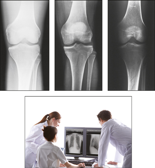
In radiography, the image receptor (IR) is the device that receives the energy of the x-ray beam and forms the image of the body part. In diagnostic radiology, the IR is one of the following five devices:
1. Cassette with film: A device that contains special intensifying screens that glow when struck by x-rays and imprints the x-ray image on film. The use of a darkroom, where the film is developed in a processor, is required. Afterward the radiographic film image is ready for viewing on an illuminator (Fig. 1-1, A).
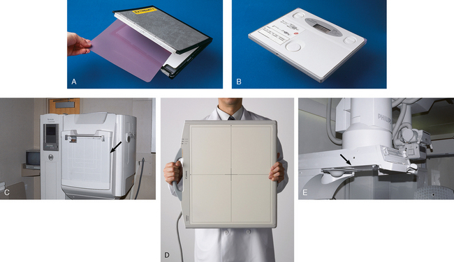
Fig. 1-1 Image receptors. A, Conventional radiographic cassette, opened and showing a sheet of x-ray film. B, CR cassette. This contains a storage-phosphor image plate that stores x-ray image. C, DR chest x-ray machine. A flat panel detector is located behind the unit (arrow) and stores x-ray image. D, Portable DR system is lightweight and can be carried anywhere for obtaining fast images. E, Fluoroscopic screen located under fluoroscopic tower (arrow) transmits x-ray image to a camera and then to a television for real-time viewing. (D, Courtesy Canon USA, Inc.)
2. Image plate (IP): A device, used for computed radiography (CR), similar to a conventional intensifying screen. The IP is housed in a specially designed cassette that contains special phosphorus to store the x-ray image. The IP is a component of the new “digital” imaging systems. The cassette is inserted into a reader device, which scans the IP with a laser. The radiographic image is converted to digital format and is viewed on a computer monitor or printed on film (Fig. 1-1, B).
3. Solid-state detectors: A flat panel thin-film transistor (TFT) detector or a charge-coupled device (CCD) used for direct digital radiography (DR). This type of digital imaging system is called “cassetteless” because it does not use a cassette or an IP. The flat panel detector or CCD built into the x-ray table or other device captures the x-ray image and converts it directly into digital format. The image is viewed on a computer monitor or printed on film (Fig. 1-1, C). This is the fastest processing system with images available in 6 seconds or less. The DR flat panel detector is a component of the new “digital” imaging systems.
4. Portable digital radiography: A portable, lightweight DR system that can be used for lateral and axial imaging of limbs and for trauma and bedside applications. Its 14 × 17 inches (35 × 43 cm) size is large enough for chest and abdomen images. The unit can be tethered to the computer via Ethernet, or the newest systems allow wireless transmission (Fig. 1-1, D).
5. Fluoroscopic screen: X-rays strike a fluoroscopic screen, where the image is formed and is transmitted to a television monitor via a camera. This is a “real-time” device in which the body part is viewed live on a television (Fig. 1-1, E).
Radiograph
Each step in performing a radiographic procedure must be completed accurately to ensure that the maximal amount of information is recorded on the image. The information that results from performing the radiographic examination generally shows the presence or absence of abnormality or trauma. This information assists in the diagnosis and treatment of the patient. Accuracy and attention to detail are essential in each radiologic examination.
The radiographer must be thoroughly familiar with the radiographic attenuation patterns cast by normal anatomy structures. To develop the ability to analyze radiographs properly and to correct or prevent errors in performing the examination, the radiographer should study radiographs from the following standpoints:
1. Superimposition: The relationship of the anatomic superimposition to size, shape, position, and angulation must be reviewed.
2. Adjacent structures: Each anatomic structure must be compared with adjacent structures and reviewed to ensure that the structure is present and properly shown.
3. Optical density (OD): OD is known as degree of blackening when associated with radiographic film and as brightness when describing appearance on a digital display monitor. The OD must be within a “diagnostic range” to display all desired anatomic structures. Images with ODs outside the diagnostic range (too light or too dark) are primarily associated with screen-film radiography (Fig. 1-2), although they are possible with digital imaging. The primary controlling factor for screen-film OD is milliampere-second (mAs). For digital imaging, the OD of displayed images is primarily controlled by automatic rescaling, so mAs selection affects patient radiation dose and image noise.
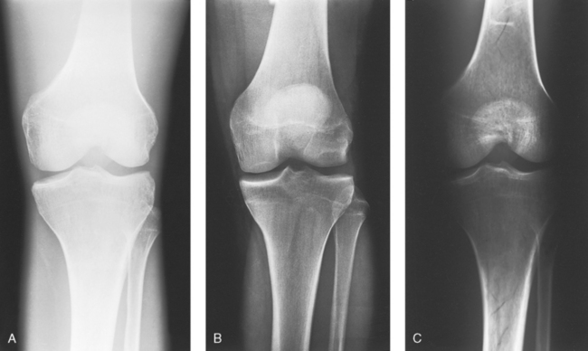
Fig. 1-2 Sufficient radiographic density is necessary to make a diagnosis. A, Radiograph of the knee with insufficient density. It is too light to make a diagnosis, and a repeat radiograph is necessary. B, Radiograph of the knee with proper density. All bony aspects of the knee are seen, including soft tissue detail around the bone. C, Radiograph of the knee with too much density—a diagnosis cannot be made, and a repeat radiograph is necessary.
4. Contrast: The contrast, or the difference in density between any two areas on a radiograph, must be sufficient to allow radiographic distinction of adjacent structures with different tissue densities. A wide range of contrast levels is produced among the various radiographic examinations performed (Fig. 1-3). A low-contrast image displays many density levels, and a high-contrast image displays few density levels. The primary controlling factor of radiographic contrast is kilovoltage peak (kVp).
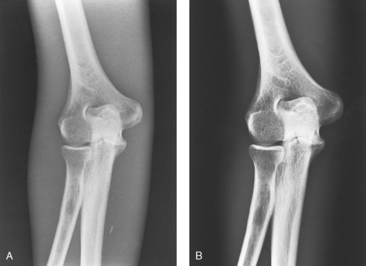
Fig. 1-3 Sufficient contrast is necessary to make a diagnosis. Two different scales of contrast are shown on the elbow. A, Long scale (low contrast). B, Short scale (high contrast).
5. Recorded detail: The recorded detail, or the ability to visualize small structures, must be sufficient to show clearly the desired anatomic part (Fig. 1-4). Recorded detail is primarily controlled by the following:
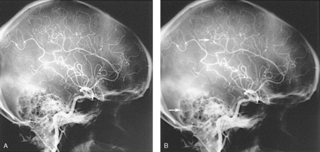
Fig. 1-4 Different levels of recorded detail. A, Excellent recorded detail is seen throughout this radiograph of the arteries in the head. B, Poor recorded detail. Note the fuzzy edges of the arteries and bony structures in this image (arrows).
6. Magnification: The magnification of the body part must be evaluated, taking into account the controlling factors of object–to–image receptor distance (OID), or how far the body part is from the IR, and source–to–image receptor distance (SID), or how far the x-ray tube is from the IR. All radiographs yield some degree of magnification because all body parts are threedimensional (Fig. 1-5).
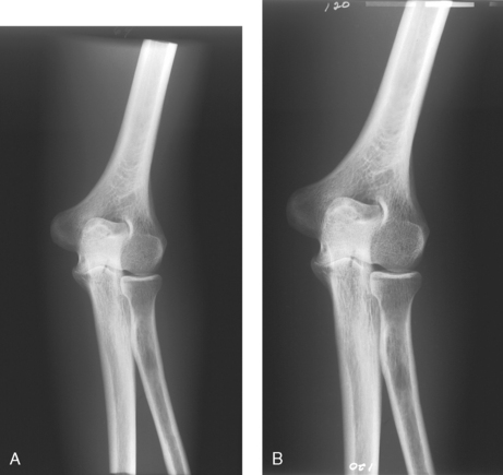
Fig. 1-5 Magnification of body part. A, AP projection of the elbow at normal magnification level. B, Same projection, with elbow magnified.
7. Shape distortion: The shape distortion of the body part must be analyzed, and the following primary controlling factors must be studied:
An example of shape distortion is when a bone is projected longer or shorter than it actually is. Distortion is the misrepresentation of the size or shape of any anatomic structure (Fig. 1-6).
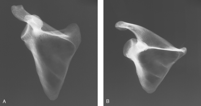
Fig. 1-6 Distortion of body part. A, Scapula bone nondistorted. B, Same bone projected shorter than in A and distorted.
A strong knowledge of anatomy and the ability to analyze radiographs correctly are paramount—especially to radiographers who work without a radiologist in constant attendance. In this situation, the patient’s physician must be able to depend on the radiographer to perform the technical phase of examinations without assistance.
DISPLAY OF RADIOGRAPHS
Radiographs are generally oriented on the display device according to the preference of the interpreting physician. Because methods of displaying radiographic images have developed largely through custom, no fixed rules have been established. The radiologist, who is responsible for making a diagnosis on the basis of the radiographic examination, and the radiographer, who performs the examination, follow traditional standards of practice, however, regarding the placement of radiographs on the viewing device. In clinical practice, the viewing device is commonly called a viewbox, or illuminator, for screen-film radiography and a display monitor for digital imaging.
ANATOMIC POSITION
Radiographs are usually oriented on the display device so that the person looking at the image sees the body part placed in the anatomic position. The anatomic position refers to the patient standing erect with the face and eyes directed forward, arms extended by the sides with the palms of the hands facing forward, heels together, and toes pointing anteriorly (Fig. 1-7). When the radiograph is displayed in this manner, the patient’s left side is on the viewer’s right side and vice versa (Fig. 1-8). Medical professionals always describe the body, a body part, or a body movement as though it were in the anatomic position.
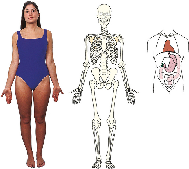
Fig. 1-7 Patient in anatomic position. Most radiographs are placed on the illuminator with the body part matching this position.
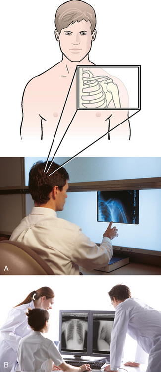
Fig. 1-8 A, Radiologist interpreting radiograph of a patient’s left shoulder. Radiograph is placed on the illuminator with the patient’s left side on the viewer’s right side. The radiologist spatially pictured the patient’s anatomy in the anatomic position and placed the radiograph on the illuminator in that position. B, Radiographs displayed correctly on a digital display. The same orientation rules apply to digital imaging. (B, Courtesy Canon USA, Inc.)
Posteroanterior and anteroposterior radiographs
Fig. 1-9, A, illustrates the anterior (front) aspect of the patient’s chest placed closest to the IR for a posteroanterior (PA) projection. Fig. 1-9, B, illustrates the posterior (back) aspect of the patient’s chest placed closest to the IR for an anteroposterior (AP) projection. Regardless of whether the anterior or posterior body surface is closest to the IR, the radiograph is usually placed in the anatomic position (Fig. 1-10). (Positioning terminology is fully described in Chapter 3.)
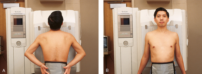
Fig. 1-9 A, Patient positioned for PA projection of the chest. Anterior aspect of the chest is closest to IR. B, Patient positioned for AP projection of the chest. Posterior aspect of the chest is closest to IR.
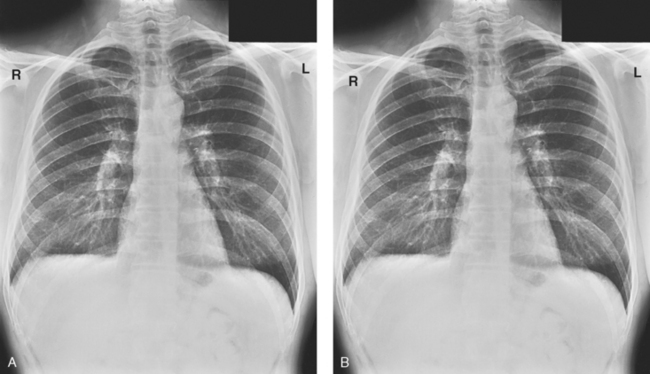
Fig. 1-10 A, PA projection of the chest. B, AP projection of the chest on the same patient as in A. Both radiographs are correctly displayed with the anatomy in the anatomic position even though the patient was positioned differently. Note the patient’s left side is on your right, as though the patient were facing you.
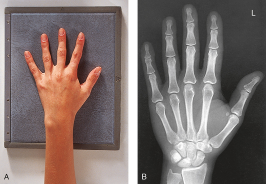
Exceptions to these guidelines include the hands, fingers, wrists, feet, and toes. Hand, finger, and wrist radiographs are routinely displayed with the digits (fingers) pointed to the ceiling. Foot and toe radiographs are also placed on the illuminator with the toes pointing to the ceiling. Hand, finger, wrist, toe, and foot radiographs are viewed from the perspective of the x-ray tube, or exactly as the anatomy was projected onto the IR (Figs. 1-11 and 1-12). This perspective means that the individual looking at the radiograph is in the same position as the x-ray tube.

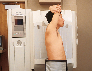
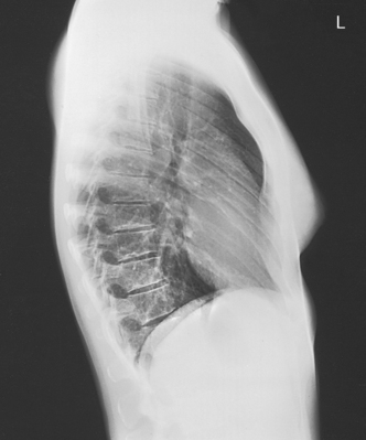
Lateral radiographs
Lateral radiographs are obtained with the patient’s right or left side placed against the IR. The patient is generally placed on the illuminator in the same orientation as though the viewer were looking at the patient from the perspective of the x-ray tube at the side where the x-rays first enter the patient—exactly like radiographs of the hands, wrists, feet, and toes. Another way to describe this is to display the radiograph so that the side of the patient closest to the IR during the procedure is also the side in the image closest to the illuminator. A patient positioned for a left lateral chest radiograph is depicted in Fig. 1-13. The resulting left lateral chest radiograph is placed on the illuminator as shown in Fig. 1-14. A right lateral chest position and its accompanying radiograph would be positioned and displayed the opposite of that shown in Figs. 1-13 and 1-14.
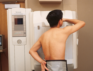
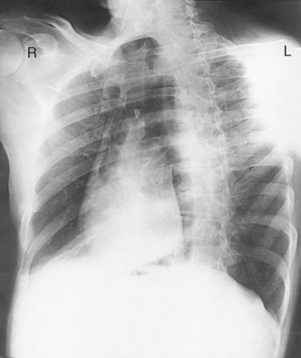
Oblique radiographs
Oblique radiographs are obtained when the patient’s body is rotated so that the projection obtained is not frontal, posterior, or lateral (Fig. 1-15). These radiographs are viewed with the patient’s anatomy placed in the anatomic position (Fig. 1-16).
Other radiographs
Many other less commonly performed radiographic projections are described throughout this atlas. The most common method of displaying the radiograph that is used in the radiology department and most clinical practice areas is generally either in the anatomic position or from the perspective of the x-ray tube; however, there are exceptions. Some physicians prefer to view all radiographs from the perspective of the x-ray tube rather than in the anatomic position. A neurosurgeon operates on the posterior aspect of the body and does not display spine radiographs in the anatomic position or from the perspective of the x-ray tube. The radiographs are displayed with the patient’s right side on the surgeon’s right side as though looking at the posterior aspect of the patient. What the surgeon sees on the radiograph is exactly what is seen in the open body part during surgery.
Clinical History
The radiographer is responsible for performing radiographic examinations according to the standard department procedure except when contraindicated by the patient’s condition. The radiologist is a physician who is board certified to read, or interpret, x-ray examinations. As the demand for the radiologist’s time increases, less time is available to devote to the technical aspects of radiology. This situation makes the radiologist more dependent on the radiographer to perform the technical aspects of patient care. The additional responsibility makes it necessary for the radiographer to know the following:
• Normal anatomy and normal anatomic variations so that the patient can be accurately positioned
• The radiographic characteristics of numerous common abnormalities
Although the radiographer is not responsible for explaining the cause, diagnosis, or treatment of the disease, the radiographer’s professional responsibility is to produce an image that clearly shows the abnormality.
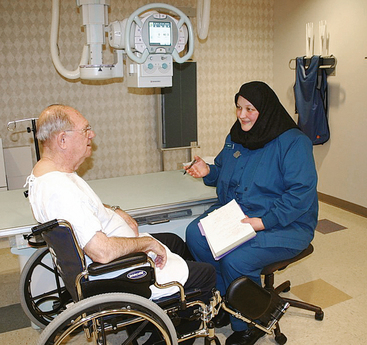
When the physician does not see the patient, the radiographer is responsible for obtaining the necessary clinical history and observing any apparent abnormality that might affect the radiographic result (Fig. 1-17). Examples include noting jaundice or swelling, body surface masses possibly casting a density that could be mistaken for internal changes, tattoos that contain ferrous pigment, surface scars that may be visible radiographically, and some decorative or ornamental clothing. The physician should give specific instructions about what information is necessary if the radiographer assumes this responsibility.
The requisition received by the radiographer should clearly identify the exact region to be radiographed and the suspected or existing diagnosis. The patient must be positioned and the exposure factors selected according to the region involved and the radiographic characteristics of the existent abnormality. Radiographers must understand the rationale behind the examination; otherwise, radiographs of diagnostic value cannot be produced. Having the information in advance prevents delay, inconvenience, and, more importantly, unnecessary radiation exposure to the patient.
With many institutions updating to electronic records, the radiographer may be using the computer system to enter information about the patient. In many of these information systems, the full patient’ history may be accessed. The radiographer needs to observe rules of confidentiality.
Advanced Clinical Practice
In response to increased demands on the radiologist’s time, a level of advanced clinical practice has developed for the radiographer. This advanced clinical role allows the radiographer to act as a “radiologist extender,” similar to the physician assistant for a primary care physician. These radiographers take a leading role in patient care activities, perform selected radiologic procedures under the radiologist’s supervision, and may be responsible for making initial image observations that are forwarded to the supervising radiologist for incorporation into the final report. The titles of radiologist assistant (RA) and radiology practitioner assistant (RPA) are currently used to designate radiographers who provide these advanced clinical services in the diagnostic imaging department. Requirements for practice include certification as a radiographer by the ARRT, pertinent additional education, and clinical experience under the supervision of a radiologist preceptor. RAs and RPAs also write advanced-level certification examinations.
Initial Examination
The radiographs obtained for the initial examination of each body part are based on the anatomy or function of the part and the type of abnormality indicated by the clinical history. The radiographs obtained for the initial examination are usually the minimum required to detect any demonstrable abnormality in the region. Supplemental studies for further investigation are made as needed. This method saves time, eliminates unnecessary radiographs, and reduces patient exposure to radiation.
Diagnosis and the Radiographer
A patient is naturally anxious about examination results and is likely to ask questions. The radiographer should tactfully advise the patient that the referring physician will receive the report as soon as the radiographs have been interpreted by the radiologist. Referring physicians may also ask the radiographer questions, and they should be instructed to contact the interpreting radiologist.
Care of the Radiographic Examining Room
The radiographic examining room should be as scrupulously clean as any other room used for medical purposes. The mechanical parts of the x-ray machine, such as the tableside, supporting structure, and collimator, should be wiped with a clean, damp (not soaked) cloth daily. The metal parts of the machine should be periodically cleaned with a disinfectant. The overhead system, x-ray tube, and other parts that conduct electricity should be cleaned with alcohol or a clean, dry cloth. Water is never used to clean electrical parts.
The tabletop should be cleaned after each examination. Cones, collimators, compression devices, gonad shields, and other accessories should be cleaned daily and after any contact with a patient. Adhesive tape residue left on cassettes and cassette stands should be removed, and the cassette should be disinfected. Cassettes should be protected from patients who are bleeding, and disposable protective covers should be manipulated so that they do not come in contact with ulcers or other discharging lesions. Use of stained or damaged cassettes is inexcusable and does not represent a professional atmosphere.
The radiographic room should be prepared for the examination before the patient arrives. The room should look clean and organized—not disarranged from the previous examination (Fig. 1-18). Fresh linens should be put on the table and pillow, and accessories needed during the examination should be placed nearby. Performing these preexamination steps requires only a few minutes but creates a positive, lasting impression on the patient; not performing these steps beforehand leaves a negative impression.
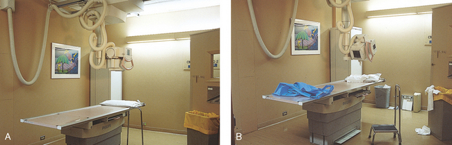
Fig. 1-18 A, Radiographic room should always be clean and straightened before any examination begins. B, This room is not ready to receive a patient. Note devices stored on the floor and previous patient’s gowns and towels lying on the table. This room does not present a welcoming sight for a patient.
Standard Precautions
Radiographers are engaged in caring for sick patients and should be thoroughly familiar with standard precautions. They should know the way to handle patients who are on isolation status without contaminating their hands, clothing, or apparatus, and radiographers must know the method of disinfecting these items when they become contaminated. Standard precautions are designed to reduce the risk of transmission of unrecognized sources of blood-borne and other pathogens in health care institutions. Standard precautions apply to:
Handwashing is the easiest and most convenient method of preventing the spread of microorganisms (Fig. 1-19, A). Radiographers should wash their hands before and after working with each patient. Hands must always be washed, without exception, in the following specific situations:
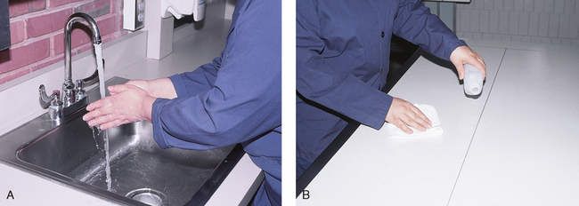
Fig. 1-19 A, Radiographers should practice scrupulous cleanliness, which includes regular handwashing. B, Radiographic tables and equipment should be cleaned with a disinfectant according to department policy.
• After examining patients with known communicable diseases
• After coming in contact with blood or body fluids
As one of the first steps in aseptic technique, radiographers’ hands should be kept smooth and free from roughness or chapping by the frequent use of soothing lotions. All abrasions should be protected by bandages to prevent the entrance of bacteria.
For the protection of the health of radiographers’ and patients’, the laws of asepsis and prophylaxis must be obeyed. Radiographers should practice scrupulous cleanliness when handling all patients, whether or not the patients are known to have an infectious disease. If a radiographer is to examine the patient’s head, face, or teeth, the patient should ideally see the radiographer perform handwashing. If this is not possible, the radiographer should perform handwashing and then enter the room drying the hands with a fresh towel. If the patient’s face is to come in contact with the IR front or table, the patient should see the radiographer clean the device with a disinfectant or cover it with a clean drape.
A sufficient supply of gowns and disposable gloves should be kept in the radiographic room to be used to care for infectious patients. After examining infectious patients, radiographers must wash their hands in warm, running water and soapsuds and rinse and dry them thoroughly. If the sink is not equipped with a knee control for the water supply, the radiographer opens the valve of the faucet with a paper towel. After proper handwashing, the radiographer closes the valve of the faucet with a paper towel.
Before bringing a patient from an isolation unit to the radiology department, the transporter should drape the stretcher or wheelchair with a clean sheet to prevent contamination of anything the patient might touch. When the patient must be transferred to the radiographic table, the table should be draped with a sheet. The edges of the sheet may be folded back over the patient so that the radiographer can position the patient through the clean side of the sheet without becoming contaminated.
A folded sheet should be placed over the end of the stretcher or table to protect the IRs when a non-Bucky technique is used. The IR is placed between the clean fold of the sheet, and with the hands between the clean fold, the radiographer can position the patient through the sheet. If the radiographer must handle the patient directly, an assistant should position the tube and operate the equipment to prevent contamination. If a patient has any moisture or body fluids on the body surface that could come in contact with the IR, a non–moisture-penetrable material must be used to cover the IR.
When the examination is finished, the contaminated linen should be folded with the clean side out and returned to the patient’s room with the patient. There the linen receives the special attention given to linen used for isolation unit patients or is disposed of according to the established policy of the institution. All radiographic tables must be cleaned after patients have touched it with their bare skin and after patients with communicable diseases have been on the table (Fig. 1-19, B).
Disinfectants and Antiseptics
Chemical substances that kill pathogenic bacteria are classified as germicides and disinfectants (e.g., dilute bleach is sometimes used as a disinfectant). Disinfection is the process of killing only microorganisms that are pathogenic. The objection to the use of many chemical disinfectants is that to be effective, they must be used in solutions so strong that they damage the material being disinfected. Chemical substances that inhibit the growth of but without killing pathogenic microorganisms are called antiseptics. Alcohol, which is commonly used for medical or practical asepsis in medical facilities, has antiseptic but not disinfectant properties. Sterilization, which is usually performed by means of heat or chemicals, is the destruction of all microorganisms.
Centers for Disease Control and Prevention
For the protection of health care workers, the U.S. Centers for Disease Control and Prevention (CDC)1 has issued recommendations for handling blood and other body fluids. According to the CDC, all human blood and certain body fluids should be treated as if they contain pathogenic microorganisms (Box 1-1). These precautions should apply to all contacts involving patients. Health care workers should wear gloves whenever they come into contact with blood, mucous membranes, wounds, and any surface or body fluid containing blood. For any procedure in which blood or other body fluids may be sprayed or splashed, the radiographer should wear a mask, protective eyewear (e.g., eye shields, goggles), and a gown.
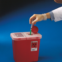
Health care workers must be cautious to prevent needle stick injuries. Needles should never be recapped, bent, broken, or clipped. Instead, they should be placed in a puncture-proof container and properly discarded (Fig. 1-20).
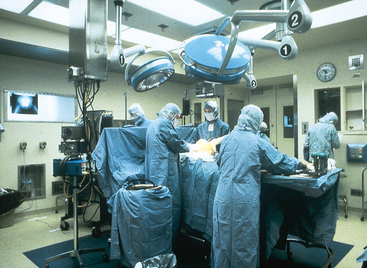
Operating Room
Chapter 29 of this atlas contains comprehensive information about the radiographer’s work in the operating room (OR). A radiographer who has not had extensive patient care education must exercise extreme caution to prevent contaminating sterile objects in the OR. The radiographer should perform handwashing and wear scrub clothing, a scrub cap, and a mask and should survey the particular setup in the OR before bringing in the x-ray equipment. By taking this precaution, the radiographer can ensure that sufficient space is available to do the work without the danger of contamination. If necessary, the radiographer should ask the circulating nurse to move any sterile items. Because of the danger of contamination of the sterile field, sterile supplies, and persons scrubbed for the procedure, the radiographer should never approach the operative side of the surgical table unless directed to do so.
After checking the room setup, the radiographer should thoroughly wipe the x-ray equipment with a damp (not soaked) cloth before taking it into the OR. The radiographer moves the mobile machine, or C-arm unit, to the free side of the operating table—the side opposite the surgeon, scrub nurse, and sterile layout (Fig. 1-21). The machine should be maneuvered into a general position that makes the final adjustments easy when the surgeon is ready to proceed with the examination.
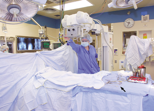
Fig. 1-21 Radiographer carefully positioning mobile x-ray tube during a surgical procedure. The sterile incision site is properly covered to maintain a sterile field. Note the sterile instruments in the foreground (arrow). The radiographer should never move radiographic equipment over uncovered sterile instruments or an uncovered surgical site.
The IR is placed in a sterile covering, depending on the type of examination to be performed. The surgeon or one of the assistants holds the sterile case open while the radiographer gently drops the IR into it, being careful not to touch the sterile case. The radiographer may give directions for positioning and securing the cassette for the exposure.
The radiographer should make the necessary arrangements with the OR supervisor when performing work that requires the use of a tunnel or other special equipment. When an IR is being prepared for the patient, any tunnel or grid should be placed on the table with the tray opening to the side of the table opposite the sterile field. With the cooperation of the surgeon and OR supervisor, a system can be developed for performing radiographic examinations accurately and quickly without moving the patient or endangering the sterile field (Fig. 1-22).
Minor Surgical Procedures in the Radiology Department
Procedures that require a rigid aseptic technique, such as cystography, intravenous urography, spinal punctures, angiography, and angiocardiography, are performed in the radiology department (Fig. 1-23). Although the physician needs the assistance of a nurse in certain procedures, the radiographer can make the necessary preparations and provide assistance in many procedures.
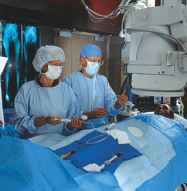
Fig. 1-23 Many radiographic procedures require strict aseptic technique, such as seen in this procedure involving passing a catheter into the patient’s femoral artery.
For procedures that do not require a nurse, the radiographer should know which surgical instruments and supplies are necessary and how to prepare and sterilize them. Radiographers may make arrangements with the surgical supervisor to acquire the education necessary to perform these procedures.
Procedure Book
A procedure or protocol book covering each examination performed in the radiology department is essential. Under the appropriate heading, each procedure should be outlined and should state the staff required and duties of each team member. A listing of sterile and nonsterile items should also be included. A copy of the sterile instrument requirements should be given to the supervisor of the central sterile supply department to assist preparation of the trays for each procedure.
Bowel Preparation
Radiologic examinations involving the abdomen often require that the entire colon be cleansed before the examination so that diagnostic-quality radiographs can be obtained. The patient’s colon may be cleansed by one or any combination of the following:
The technique used to cleanse the patient’s colon generally is selected by the medical facility or physician. The patient should be questioned about any bowel preparation that may have been completed before an abdominal procedure is begun. For additional information on bowel preparation, see Chapter 17.
Motion and Its Control
Patient motion plays a large role in radiography (Fig. 1-24). Because motion is the result of muscle action, the radiographer needs to have some knowledge about the functions of various muscles. The radiographer should use this knowledge to eliminate or control motion for the exposure time necessary to complete a satisfactory examination. The three types of muscular tissue that affect motion are the following:
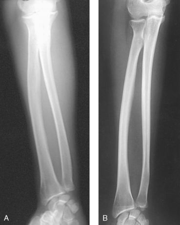
Fig. 1-24 A, Forearm radiograph of a patient who moved during the exposure. Note the fuzzy appearance of the edges of the bones. B, Radiograph of patient without motion.
INVOLUNTARY MUSCLES
The visceral (organ) muscles are composed of smooth muscular tissue and are controlled partially by the autonomic nervous system and the muscles’ inherent characteristics of rhythmic contractility. By their rhythmic contraction and relaxation, these muscles perform the movement of the internal organs. The rhythmic action of the muscular tissue of the alimentary tract, called peristalsis, is normally more active in the stomach (about three or four waves per minute) and gradually diminishes along the intestine. The specialized cardiac muscular tissue functions by contracting the heart to pump blood into the arteries and expanding or relaxing to permit the heart to receive blood from the veins. The pulse rate of the heart varies with emotions, exercise, diet, size, age, and gender.
VOLUNTARY MUSCLES
The voluntary, or skeletal, muscles are composed of striated muscular tissue and are controlled by the central nervous system. These muscles perform the movements of the body initiated by the individual. In radiography, the patient’s body must be positioned in such a way that the skeletal muscles are relaxed. The patient’s comfort level is a good guide to determine the success of the position.
Voluntary motion resulting from lack of control is caused by the following:
Voluntary muscle control
The radiographer can control voluntary patient motion by doing the following:
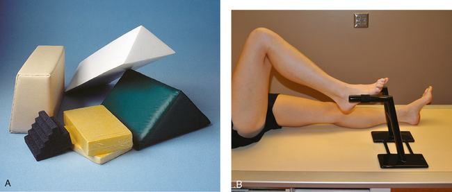
Decreasing the length of exposure time is the best way to control voluntary motion that results from mental illness or the age of the patient. Immobilization for limb radiography can often be obtained for the duration of the exposure by having the patient phonate an mmm sound with the mouth closed or an ahhh sound with the mouth open. The radiographer should always be watching the patient during the exposure to ensure that the exposure is made during suspended respiration. Sponges and sandbags are commonly used as immobilization devices (Fig. 1-25, A). A leg holder is used to stabilize the opposite leg for lateral radiographs of the legs, knee, femur, and hip (Fig. 1-25, B). A thin radiolucent mattress, called a table pad, may be placed on the radiographic table to reduce movement related to patient discomfort caused by lying on the hard surface. These table pads should not be used when the increased OID would result in unacceptable magnification, such as in radiography of the limbs. If possible, radiographers should use table pads under the patient in the body areas where the projections are not made.
Patient Instructions
When an examination requires preparation, such as in kidney and gastrointestinal examinations, the radiographer must carefully instruct the patient. Although the particular examination or procedure may be repetitive to the radiographer, it is new to the patient. Frequently, what a radiographer interprets as patient stupidity results from lack of sufficiently explicit directions. The radiographer must ensure that the patient understands not only what to do, but also why it must be done. A patient is more likely to follow instructions correctly if the reason for the instructions is clear. If the instructions are complicated, they should be written out and verbally reviewed with the patient if necessary. Few patients know the way to give themselves an enema correctly, so the radiographer should question the patient and, when necessary, take the time to explain the correct procedure. This approach often saves film, time, and radiation exposure to the patient.
Patient’s Attire, Ornaments, and Surgical Dressings
The patient should be dressed in a gown that allows exposure of limited body regions under examination. A patient is never exposed unnecessarily; a sheet should be used when appropriate. If a region of the body needs to be exposed to complete the examination, only the area under examination should be uncovered while the rest of the patient’s body is completely covered for warmth and privacy. When the radiographer is examining parts that must remain covered, disposable paper gowns or cotton cloth gowns without metal or plastic snaps are preferred (Fig. 1-26). If washable gowns are used, they should not be starched; starch is radiopaque, which means it cannot be penetrated easily by x-rays. Any folds in the cloth should be straightened to prevent confusing densities on the radiograph. The length of exposure should also be considered. Material that does not cast a density on a heavy exposure, such as that used on an adult abdomen, may show clearly on a light exposure, such as that used on a child’s abdomen.
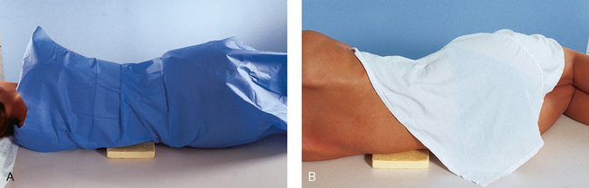
Fig. 1-26 A, A female patient wearing a disposable paper gown and positioned for a lateral projection of the lumbar spine. Private areas are completely covered. The gown is smoothed around the contour of the body for accurate positioning. B, The same patient wearing a traditional cloth hospital gown. The gown is positioned for maximal privacy.
Any radiopaque object should be removed from the region to be radiographed. Zippers, necklaces, snaps, thick elastic, and buttons should be removed when radiographs of the chest and abdomen are produced (Fig. 1-27). When radiographing the skull, the radiographer must make sure that dentures, removable bridgework, earrings, necklaces, and all hairpins are removed.
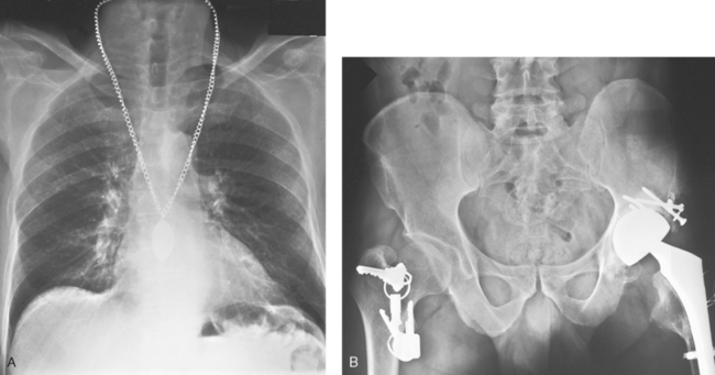
Fig. 1-27 A, A necklace was left on for this chest radiograph. B, Keys were left in the pocket of a lightweight hospital robe during the examination of this patient’s pelvis. Both radiographs had to be repeated because the metal objects were not removed before the examination.
When the abdomen, pelvis, or hips of an infant are radiographed, the diaper should be removed. Because some diaper rash ointments are radiopaque, the area may need to be cleansed before the procedure.
Surgical dressings, such as metallic salves and adhesive tape, should be examined for radiopaque substances. If permission to remove the dressings has not been obtained or the radiographer does not know how to remove them and the radiology department physician is not present, the surgeon or nurse should be asked to accompany the patient to the radiology department to remove the dressings. When dressings are removed, the radiographer should always ensure that a cover of sterile gauze adequately protects open wounds.
Handling of Patients
Patients who are coherent and capable of understanding should be given an explanation of the procedure to be performed. Patients should understand exactly what is expected and be made comfortable. If patients are apprehensive about the examination, their fears should be alleviated. If the procedure will cause discomfort or be unpleasant, such as with cystoscopy and intravenous injections, the radiographer should calmly and truthfully explain the procedure. Patients should be told that it will cause some discomfort or be unpleasant, but because the procedure is a necessary part of the examination, full cooperation is necessary. Patients usually respond favorably if they understand that all steps are being taken to alleviate discomfort.
Because the entire procedure may be a new experience, patients usually respond incorrectly when given more than one instruction at a time. For example, when instructed to get up on the table and lie on the abdomen, a patient may get onto the table in the most awkward possible manner and lie on his or her back. Instead of asking a patient to get onto the table in a specific position, the radiographer should first have the patient sit on the table and then give instructions on assuming the desired position. If the patient sits on the table first, the position can be assumed with less strain and fewer awkward movements. The radiographer should never rush a patient. If patients feel hurried, they will be nervous and less able to cooperate. When moving and adjusting a patient into position, the radiographer should manipulate the patient gently but firmly; a light touch can be as irritating as one that is too firm. Patients should be instructed and allowed to do as much of the moving as possible.
X-ray grids move under the radiographic table, and with floating or moving tabletops, patients may injure their fingers. To reduce the possibility of injury, the radiographer should inform patients to keep their fingers on top of the table at all times. Regardless of the part being examined, the patient’s entire body must be adjusted with resultant motion or rotation to prevent muscle pull in the area of interest. When a patient is in an oblique (angled) position, the radiographer should use support devices and adjust the patient to relieve any strain. Immobilization devices and compression bands should be used whenever necessary, but not to the point of discomfort. The radiographer should be cautious when releasing a compression band over the abdomen and should perform the procedure slowly.
When making final adjustments to a patient’s position, the radiographer should stand with the eyes in line with the position of the x-ray tube, visualize the internal structures, and adjust the part accordingly. Although there are few rules on positioning patients, many repeat examinations can be eliminated by following these guidelines. (See Chapters 26 and 27 for handling instructions for pediatric and geriatric patients.)
ILL OR INJURED PATIENTS
Great care must be exercised in handling trauma patients, particularly patients with skull, spinal, and long bone injuries. A physician should perform any necessary manipulation to prevent the possibility of fragment displacement. The positioning technique should be adapted to each patient and necessitate as little movement as possible. If the tube-part-imaging plane relationship is maintained, the resultant projection is the same regardless of the patient’s position.
When a patient who is too sick to move alone must be moved, the following considerations should be kept in mind:
1. The patient should be moved as little as possible.
2. The radiographer should never try to lift a helpless patient alone.
3. To prevent straining the back muscles when lifting a heavy patient, one should flex the knees, straighten the back, and bend from the hips.
4. When a patient’s shoulders are lifted, the head should be supported. While holding the head with one hand, one slides the opposite arm under the shoulders and grasps the axilla so that the head can rest on the bend of the elbow when the patient is raised.
5. When moving the patient’s hips, the patient’s knees are flexed first. In this position, patients may be able to raise themselves. If not, lifting the body when the patient’s knees are bent is easier.
6. When a helpless patient must be transferred to the radiographic table from a stretcher or bed, he or she should be moved on a sheet by at least four and preferably six people. The stretcher is placed parallel to and touching the table. Under ideal circumstances, at least three people should be stationed on the side of the stretcher and two on the far side of the radiographic table to grasp the sheet at the shoulder and hip levels. One person should support the patient’s head, and another person should support the feet. When the signal is given, all six people should smoothly and slowly lift and move the patient in unison (Fig. 1-28, A). Often, radiographers use the three-person move for patients who are not in a critical condition (Fig. 1-28, B).
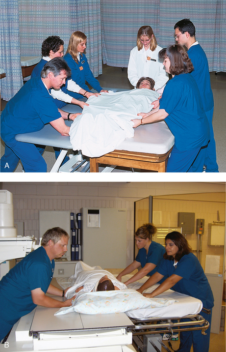
Fig. 1-28 A, Technique for a six-person transfer of a patient who is unable to move from a cart to the procedure table. Note the person holding and supporting the head. B, Three-person transfer of a patient back onto the cart. Note two people are always on the side that is pulling the patient, and one person is on the opposite side pushing the patient. Note also the backs of the three people are straight, following correct lifting and moving practices.
Many hospitals now have a specially equipped radiographic room adjoining the emergency department. These units often have special radiographic equipment and stretchers with radiolucent tops that allow severely injured patients to be examined on the stretcher and in the position in which they arrive. A mobile radiographic machine is often taken into the emergency department and radiographs are exposed there. Where this ideal emergency setup does not exist, trauma patients are often conveyed to the main radiology department. There they must be given precedence over nonemergency patients (see Chapters 13 and 28).
Age-Specific Competencies
Age-specific competence is defined as the knowledge, skills, ability, and behaviors that are essential for providing optimal care to defined groups of patients. Examples of defined groups include neonatal, pediatric, adolescent, and geriatric patients. Appropriate staff competence in working with these diverse patient groups is crucial in providing quality patient care. The Joint Commission1 requires that age-specific competencies be written for all health care personnel who provide direct patient care. Radiographers are considered direct patient care providers. The Joint Commission requires radiology departments to document that radiographers maintain competency in providing radiologic examinations to defined groups of patients.
Age-specific competence is based on the knowledge that different groups of patients have special physical and psychosocial needs. Different types and levels of competence are required for specific patient populations. A radiographer who is obtaining radiographic images on a neonatal or pediatric patient must be skilled at interpreting nonverbal communication. Working with a geriatric patient requires the radiographer to have the knowledge and skills necessary to assess and maintain the integrity of fragile skin.
Health care facilities that provide patient care may classify the different age groups for which age-specific competence is defined. Some hospitals may classify patients by chronologic age, some may use functional age, and others may use life stage groupings.1,2 Specialty organizations, such as pediatric hospitals, veterans’ hospitals, psychiatric hospitals, or long-term care facilities, might use institution-specific criteria, such as premature or newborn, Vietnam veteran, closed ward, or Alzheimer’ disease.
The principle supporting age-related competencies is that staff involved in direct patient care who are not competent to provide care to patients in specific age or functional groups can alter treatment, increase patient complaints about care, make serious medical errors, and increase operational costs. The Joint Commission looks for evidence of staff development programs that are effective and ongoing and serve to maintain and improve staff competence.
When the Joint Commission surveys organizations, it looks for evidence of competence assessment primarily in personnel records. The Joint Review Committee on Education in Radiologic Technology (JRCERT), the organization that accredits radiography programs, makes site visits of radiography programs and looks for evidence that students not only learn the basic theories supporting age-related competence, but also are competent. Table 1-1 shows a checklist that can be used in a radiography program to document that a student has shown basic competence in several different life stages. Box 1-2 provides examples of agespecific competencies that should be required of a radiographer. Health care facilities are required to prepare age-related competencies for all age groups, including neonates, infants, children, adolescents, adults, and geriatrics.
TABLE 1-1
Age-specific criteria checklist
This planning tool is an example of a general checklist that can assist organizations in assessing age-specific competencies of staff

Used with permission from the Joint Commission, Oakbrook Terrace, Ill, 1998.
Merrill’s Atlas essentially addresses the normal adult patient in the age group from about 18 to 60 years. Although an organization would have published age-specific competencies for this broad age group, this group could be considered the “standard group” for which radiologic procedures are standardized and written. Radiographers must learn the specifics of how to adapt and modify procedures for the extreme groups, such as neonates and geriatric patients, and those in between, such as adolescents.
Identification of Radiographs
All radiographs must include the following information (Fig. 1-29, A):
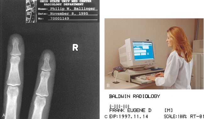
Fig. 1-29 A, All radiographs must be permanently identified and should contain a minimum of four identification markings. B, Radiographer using CR system and entering a patient’s identification data into a computer in the radiography room. C, Resulting laser image showing the patient’s information.
Correct identification is vital and should always be confirmed. Identification is absolutely vital in comparison studies, on follow-up examinations, and in medicolegal cases. Radiographers should develop the habit of rechecking the identification side marker just before placing it on the IR. Digital systems introduced in recent years use a computer in the radiography room. The radiographer inputs the patient’s identification and other data directly on each radiograph via the computer (Fig. 1-29, B and C). Side markers should still be physically placed on the IR, however. The computer should not be used to place right and left markers on the image.
Other patient identification information includes the patient’s age or date of birth, time of day, and the name of the radiographer or attending physician. For certain examinations, the radiograph should include such markings as cumulative time after introduction of contrast medium (e.g., 5 minutes postinjection) and the level of the fulcrum (e.g., 9 cm) in tomography. Other radiographs are marked to indicate the position of the patient (e.g., upright, decubitus) or with other markings specified by the institution.
Numerous methods of marking radiographs for identification are available. These methods include radiographing the identification information along with the part, “flashing” it onto the film in the darkroom before development, writing it on the film after it has been processed, perforating the information on the film, and attaching adhesive labels. Although most patient information is automatically added to digital images, additional information may be typed on the image after processing. This is commonly called annotation.
Anatomic Markers
Each radiograph must include an appropriate marker that clearly identifies the patient’s right (R) or left (L) side. Medicolegal requirements mandate that these markers be present. Radiographers and physicians must see them to determine the correct side of the patient or the correct limb. Markers are typically made of lead and placed directly on the IR or tabletop. The marker is seen on the image along with the anatomic part (Fig. 1-30). Writing the R or L by hand on a radiograph after processing is unacceptable. The only exception may be for certain projections performed during surgical and trauma procedures. Box 1-3 presents the specific rules of marker placement.
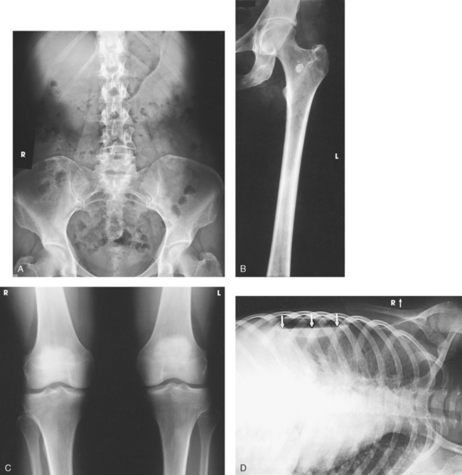
Fig. 1-30 A, AP projection of the abdomen showing right (R) marker. B, AP projection of the left limb showing left (L) marker on outer margin of the image. C, AP projection of the right and left knees on one image showing R and L markers. D, AP projection of the chest performed in the left lateral decubitus position showing R marker on the “upper” portion of IR.
Basic marker conventions include the following:
• The marker should never obscure anatomy.
• The marker should never be placed over the patient’s identification information.
• The marker should always be placed on the edge of the collimation border.
• The marker should always be placed outside of any lead shielding.
• R and L markers must be used with CR and DR digital imaging.
DIGITAL IMAGING
The development of digital imaging and the use of CR and DR have enabled an environment in which the R and L markers can be placed on the image electronically at the computer workstation. This is not recommended because of the great potential for error and legal implications; this is especially true when patients are examined in the prone position. Anatomic markers should be placed on the CR cassette or DR table similar to screen-film cassettes. Additionally, markers should never be placed on the body part.
Image Receptor Placement
The part to be examined is usually centered on the center point of the IR or to the position where the angulation of the central ray projects it to the center. The IR should be adjusted so that its long axis lies parallel with the long axis of the part being examined. Although a long bone angled across the radiograph does not impair the diagnostic value of the image, such an arrangement can be aesthetically distracting. The three general positions of the IR are shown in Fig. 1-31. These positions are named on the basis of their position in relation to the long axis of the body. The longitudinal IR position is the most frequently used position.
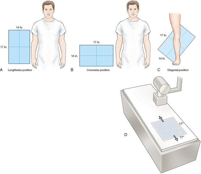
Fig. 1-31 A, Lengthwise position of IR for AP projection of the abdomen. B, Crosswise position of IR for AP projection of the pelvis. C, Diagonal position of IR for AP projection of the leg to include the knee and ankle joints. D, Position of built-in DR flat panel IR detector at 17 × 17 inches (43 × 43 cm). Flat panel detector is moveable lengthwise with the grid under the table.
Although the lesion may be known to be at the midbody (central portion) of a long bone, an IR large enough to include at least one joint should be used on all long bone studies (Fig. 1-32). This method is the only means of determining the precise position of the part and localizing the lesion. Many institutions require that both joints be shown when a long bone is initially radiographed. For tall patients, two exposures may be required, one for the long bone and joint closest to the area of concern and a second to show the joint at the opposite end.
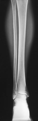
Fig. 1-32 AP projection of the leg showing the ankle joint included on the image. One joint should be shown on all images of long bones.
An IR just large enough to cover the region being examined should always be used. In addition to being extravagant, large IRs include extraneous parts that detract from the appearance of the radiograph and, more important, cause unnecessary radiation exposure to the patient. The exception to this rule is when using DR with a 17- × 17-inch (43- × 43-cm) IR built into the table. The radiographer has to collimate exactly to the body part size anywhere on the detector.
A standard rule in radiography is to place the object as close to the IR as possible. When obtaining lateral images of the middle and ring fingers, the radiographer increases the OID so that the part lies parallel with the IR. In some situations, this rule is modified. Although magnification is greater, less distortion occurs. The radiographer can increase the SID to compensate for the increase in OID, reducing magnification. In certain instances, intentional magnification is desirable and can be obtained by positioning and supporting the object between the IR and the focal spot of the tube. This procedure is known as magnification radiography.
For ease of comparison, bilateral examinations of small body parts may be placed on one IR. Exact duplication of the location of the images on the film is difficult, however, if the IR is not marked accurately. Many IRs have permanent markings on the edges to assist the radiographer in equally spacing multiple images on one IR. Depending on the size and shape of the body part being radiographed, the IR can be divided in half either transversely or longitudinally. In some instances, the IR may be divided into thirds or fourths (Fig. 1-33).
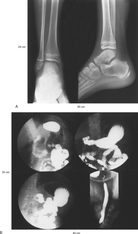
Fig. 1-33 Examples of multiple exposures on one film. A, AP and lateral projections of the ankle radiographically exposed side by side on 10- × 12-inch (24- × 30-cm) film. B, Four projections of the stomach directly imaged on 14- × 17-inch (35- × 43-cm) film.
Body parts must always be identified by right or left side and placed on the IR in the same manner, either facing or backing each other, according to established routines. The radiographer plans the exposures so that the image identification marker does not interfere with the part of interest.
English-Metric Conversion and Film Sizes
Measures are the standards used to determine size. People in the United States and a few other countries use standards that belong to the customary, or English, system of measurement. Although this system was developed in England, people in nearly all other countries including England now use the metric system of measurement.
In the past couple of decades, efforts have been made to convert all English measurements to the world standard metric system. These efforts have not been particularly effective. Nevertheless, total conversion to the metric system most likely will occur in the future.
The following information is provided to assist the radiographer in converting measurements from the English system to the metric system and vice versa:
Radiographic film is manufactured in English and metric sizes. Most sizes used in the United States have more recently been converted to metric. (Table 1-2 lists the most common film sizes used in radiology departments in the United States along with their general usage.) Four of the 11 common sizes continue to be manufactured in an English size, however. The 24- × 30-cm size has replaced the 10- × 12-inch size. The 10- × 12-inch size continues to be manufactured for use in grid cassettes. Few, if any, English sizes are used outside the United States. Four of the former English film sizes are no longer manufactured. Several additional film sizes are used routinely in departments outside the United States, including the 30- × 40-cm and 40- × 40-cm sizes.
TABLE 1-2
Most common radiology film sizes used in United States*
| Current film sizes | Former film sizes† | Usage‡ |
| 18 × 24 cm | Mammography | |
| 8 × 10 inches | General examinations | |
| 24 × 24 cm | 9 × 9 inches | Fluoroscopic spots |
| 24 × 30 cm | General examinations and mammography | |
| 10 × 12 inches | General examinations (grid cassettes) | |
| 18 × 43 cm | 7 × 17 inches | Forearms, legs |
| 30 × 35 cm | 11 × 14 inches | General examinations |
| 35 × 35 cm | Fluoroscopic spots | |
| 35 × 43 cm | 14 × 17 inches | General examinations |
| 14 × 36 inches | Upright spine | |
| 14 × 51 inches | Upright hip-to-ankle |
*In order of smallest to largest size.
†English sizes no longer in use.
‡Most common uses in United States. Outside United States, usage may differ.
CR plates are generally manufactured in five sizes. Many departments use only the 10- × 12-inch (24- × 30-cm) and 14- × 17-inch (35- × 43-cm) plates for all routine images (Table 1-3).
TABLE 1-3
Most common computed radiography plate sizes*
| Inches | Centimeters |
| 8 × 10 | 18 × 24 |
| 10 × 12 | 24 × 30 |
| 14 × 14 | 35 × 35 |
| 14 × 17 | 35 × 43 |
| 14 × 36 | 35 × 91 |
Direction of Central Ray
The central or principal beam of rays, simply referred to as the central ray (CR), is always centered to the IR unless receptor displacement is being used. The CR is angled through the part of interest under the following conditions:
• When overlying or underlying structures must not be superimposed
• When a curved structure, such as the sacrum or coccyx, must not be stacked on itself
• When projection through angled joints, such as the knee joint and lumbosacral junction, is necessary
• When projection through angled structures must be obtained without foreshortening or elongation, such as with a lateral image of the neck of the femur
The general goal is to place the CR at right angles to the structure. Accurate positioning of the part and accurate centering of the CR are of equal importance in obtaining a true structural projection.
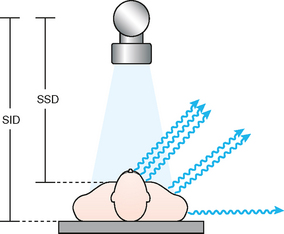
Source–to–Image Receptor Distance
SID is the distance from the anode inside the x-ray tube to the IR (Fig. 1-34). SID is an important technical consideration in the production of radiographs of optimal quality. This distance is a critical component of each radiograph because it directly affects magnification of the body part, the recorded detail, the radiographic density, and the dose to the patient. The greater the SID, the less the body part is magnified and the greater the recorded detail. SID of 40 inches (102 cm) traditionally is used for most conventional examinations. In recent years, the SID has increased to 48 inches (122 cm) in some departments.1 2 3 4 5 6 SID must be established for each radiographic projection, and it must be indicated on the technique chart.
For some radiographic projections, SID less than 40 inches (<102 cm) is desirable. In certain examinations, such as examination of the odontoid in the open-mouth position, a short SID of 30 inches (76 cm) may be used. Some textbooks state that images should not be done at SID less than 40 inches because of the dose to the patient. For some projections, the best image possible is obtained at SID 30 inches or less because it increases the field-of-view. Additionally, dose is not increased because the shorter SID prompts a lower mAs. To maintain density when going from a 40-inch SID to a 30-inch SID, the mAs can be reduced 44%, and there is an accompanying reduction in dose to the patient. The goal in these reduced SID images is to show the body part with one image and avoid a repeat or second projection.
Conversely, a longer than standard SID is used for some radiographic projections. In chest radiography, a 72-inch (183-cm) SID is the minimum distance, and in many departments a distance up to 120 inches (305 cm) is used. These long distances are necessary to ensure that the lungs fit onto the 14-inch (35-cm) width of the IR (via reduced magnification of the body part) and, most importantly, to ensure that the heart is not technically enlarged for diagnoses of cardiac enlargement.
SOURCE–TO–IMAGE RECEPTOR DISTANCE IN THIS ATLAS
When a specific SID is necessary for optimal image quality, it is identified on the specific projection’s page. The sample exposure technique charts in each chapter identify the traditional SID of 40 inches (102 cm). The special SID projections vary from 30 inches (76 cm) to 120 inches (305 cm) for general projections.
SOURCE-TO-SKIN DISTANCE
The distance between the radiography tube and the skin of the patient is termed the source-to-skin distance (SSD) (see Fig. 1-34). This distance affects the dose to the patient and is regulated by the National Council on Radiation Protection (NCRP). The current NCRP regulations state that the SSD shall not be less than 12 inches (<30 cm) and should not be less than 15 inches (<38 cm).1
Collimation of X-ray Beam
The beam of radiation must be narrow enough to irradiate only the area under examination. This restriction of the x-ray beam serves two purposes. First, it minimizes the amount of radiation to the patient and reduces the amount of scatter radiation that can reach the IR. Second, it produces radiographs that show excellent recorded detail and increased radiographic contrast by reducing scatter radiation, producing a shorter scale of contrast, and preventing secondary radiation from unnecessarily exposing surrounding tissues, with resultant image fogging (Fig. 1-35). Many experts regard collimation as the most important aspect of producing an optimal image. Collimation is equally important when using digital systems.
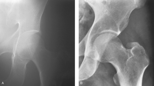
Fig. 1-35 Radiographs of the hip joint and acetabulum. A, Collimator inadvertently opened to size 14 × 17 inches (35 × 43 cm). Scatter and secondary radiation have reduced radiographic contrast and a poor-quality image results. B, Collimator set correctly to 8 × 10 inches (18 × 24 cm), improving radiographic contrast and visibility of detail.
The area of the beam of radiation is reduced to the required size by using an automatic collimator or a specifically shaped diaphragm constructed of lead or other metal with high radiation absorption capability. Because of beam restriction, the peripheral radiation strikes and is absorbed by the collimator metal, and only x-rays in the exit aperture are transmitted to the exposure field.
DIGITAL RADIOGRAPHY
With the introduction of DR imaging systems, there are no film cassettes or imaging plates used as the IR. The table or upright unit contains a 17- × 17-inch (43- × 43-cm) flat panel detector (see Fig. 1-31, D). When using cassettes or plates, the collimator automatically adjusts to the size of the IR, or the radiographer could manually reduce collimation when necessary. Collimating to large was seldom a problem. Without cassettes or plates in DR, the collimator has to be manually adjusted by the radiographer to the correct field size. This environment has prompted numerous technical problems in recent years because radiographers have collimated larger than the anatomic area in an effort to avoid clipping anatomy, or they simply try to make their jobs easier.
It is a violation of the Code of Ethics to collimate larger than the required field size. When collimating larger than the required area, the patient receives unnecessary radiation to areas not needed on the image (Fig. 1-36, A). In addition, the increased scatter radiation decreases the contrast and recorded detail in the image, reducing the ability to ensure an accurate diagnosis. When using DR systems, the collimator should be adjusted to the same anatomic area size or smaller that would be used for a cassette or plate (Fig. 1-36, B). This adjustment has to be manually done on the collimator for each projection performed.
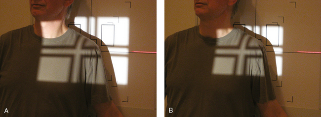
Fig. 1-36 A, Collimation set too large for AP projection of the shoulder. Note unnecessary radiation of thyroid, sternum, and general thoracic tissues. With this large collimation, more than half of the radiation strikes the table directly and results in increased scatter. B, Collimation set correctly to 10 × 12 inches (24 × 30 cm). Less tissue receives radiation, and less scatter is produced from the radiation striking table.
The software included in the computers of DR systems allows for shuttering. Shuttering is used in DR to provide a black background around the original collimation edges. This black background eliminates the distracting clear areas and the associated brightness that comes through to the eyes. Many radiographers open the collimator larger than is necessary and use the shuttering software to “crop-in” or mask unwanted peripheral image information and create the appearance of proper collimation. This technique irradiates patients unnecessarily, increases scatter radiation, decreases contrast, and increases the radiation dose. Shuttering is an image aesthetic only and should not be a substitute for proper and accurate collimation of the body part. Each projection in this atlas describes exactly the size of the collimation that should be used with DR systems.
Gonad Shielding
The patient’s gonads may be irradiated when radiographic examinations of the abdomen, pelvis, and hip areas are performed. When practical, gonad shielding should always be used to protect the patient. Contact, shadow, and large part area shields are used for radiography examinations (Figs. 1-37 through 1-39). The Center for Devices of Radiological Health has developed guidelines recommending gonad shielding in the following instances1:
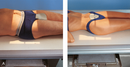
Fig. 1-37 A, Contact shield placed over the gonads of a male patient. B, Contact shield placed over the gonads of a female patient.
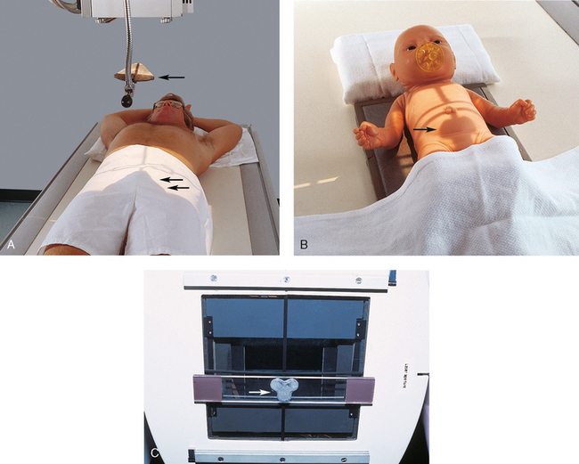
Fig. 1-38 A, Shadow shield used on a male patient. Triangular lead device (arrow) is hung from the x-ray tube and positioned so that its shadow falls on the gonads (double arrows). B, Shadow shield used on female infant. Cloverleaf shield is positioned under the collimator with magnets so that its shadow falls over the gonads (arrow). C, Cloverleaf-shaped shadow shield (arrow) positioned under the collimator with magnets.
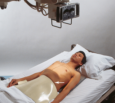
Fig. 1-39 Large piece of flexible lead (arrow) is draped over this patient’s pelvis to protect the gonads during mobile radiography examination of the chest.
• If the gonads lie within or close to (about 5 cm from) the primary x-ray field despite proper beam limitation
• If the clinical objective of the examination is not compromised
Gonad shielding is often appropriate when limbs are radiographed with the patient seated at the end of the radiographic table (see Fig. 1-11). To ensure that shielding is used appropriately, many departments have a policy that states that the gonads be shielded on every patient and for every projection in which the lead shield would not interfere with the image. Finally, gonad shielding must be considered and used when requested by the patient unless it is contraindicated. Gonad shielding is included in selected illustrations in this atlas.
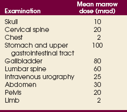
BONE MARROW DOSE
An organ of particular concern is the bone marrow. Bone marrow dose is used to estimate the population mean marrow dose (MMD) as an index of the somatic effect of radiation exposure. Table 1-4 relates the MMD associated with various radiographic examinations. Each of these doses results from partial-body exposure and is averaged over the entire body.
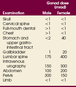
GONAD DOSE
Exposure of the gonads to radiation during diagnostic radiology is of concern because of the possible genetic effects of x-radiation. Table 1-5 indicates average gonad doses received during various radiographic examinations. The large difference between males and females results from the shielding of the ovaries by overlying tissue.
Digital Imaging
Since the discovery of x-rays in 1895, digital imaging has prompted some of the most technically significant changes in the way radiographs are produced. These systems use computers and digital systems to display the radiographic image. Radiography departments worldwide are slowly converting to digital systems. In the future, all radiographs may eventually be done with digital or some other type of digital technology.
Computed radiography (CR) involves conventional radiographic projection radiography in which the latent image (the unseen image) is produced in digital format using computer technology. The CR system uses a conventional radiography machine and conventional positioning and technical factors. The IR consists of a phosphor material plate that is similar to a conventional intensifying screen, inside a closed cassette rather than on a film in a light-tight cassette. These storagephosphor IRs are often referred to as “plates” or “imaging plates” (IPs). After exposure the CR cassette is inserted into an image reader device (Fig. 1-40), where it is scanned by a laser beam, and the final image appears on a computer monitor. The radiographer can either adjust the image for appropriate density and contrast and then print it on laser film or store the image in the computer to be read directly from the monitor by the radiologist (Fig. 1-41). A darkroom and film processor are not used with CR systems.
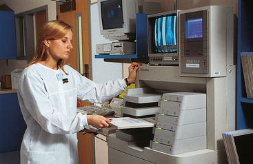
Fig. 1-40 Radiographer inserting IP into an image reader unit on CR system. The unit scans the plate with a laser beam and places the digitized image of the body part in a computer for reading on a monitor or, if necessary, for printing on a laser film.
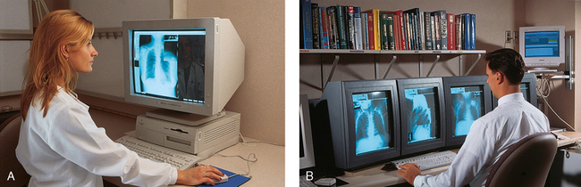
Fig. 1-41 A, Radiographer at the monitor uses the mouse to adjust the CR image of the body part to the proper size, density, and contrast before electronically sending the image for reading. B, Radiologist at the monitor is reading several CR images on one patient.
The newest digital x-ray systems are called digital radiography (DR) systems. These are similar to CR systems but do not use any type of cassette. The IR, a solid-state flat panel or CCD detector that receives the x-ray image, is built into the x-ray table or wall unit (Fig. 1-42). The built-in IR is 17 × 17 inches (43 × 43 cm) to accommodate lengthwise and crosswise projections (see Fig. 1-31, D). An IP reader unit is unnecessary for the solid-state detectors. The image is immediately displayed on the computer monitor after exposure.
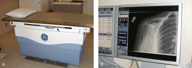
Fig. 1-42 A, DR x-ray table. The flat panel detector system is built into the table (arrow). There is no Bucky tray for a cassette. B, Image is immediately displayed on the monitor in the x-ray room for viewing.
Attention to detail is paramount when the radiographer is using CR or DR. The following sections address the technical considerations that are different from those used in conventional radiography.
KILOVOLTAGE
Because of the wider dynamic range of digital systems, a specific kVp setting is not as critical as in conventional radiography. A slightly higher kVp setting may be acceptable for a specific radiography projection. Using a kVp that is too low and does not penetrate the part adequately can create a poor-quality image (Fig. 1-43), however. Slightly overpenetrating the body part is better than underpenetrating it. An optimal kVp range should be posted on the technique chart for all projections using digital systems. In addition, for body parts that have different thicknesses of structures and densities but must be imaged on one projection (e.g., a femur), the thickest part must be well penetrated. Compensating filters should be used for body parts that have extreme differences in tissue density (see Chapter 2).
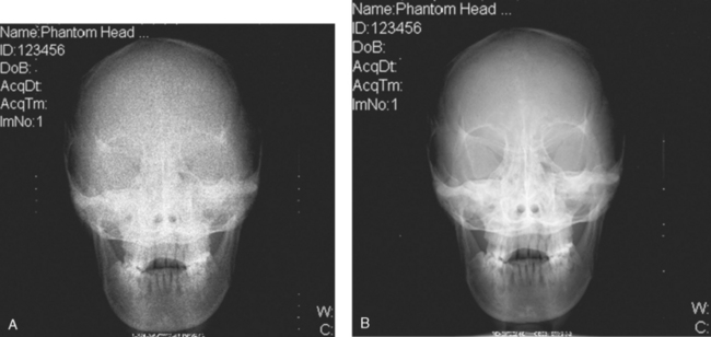
Fig. 1-43 CR images showing effect of underpenetration. A, AP projection of the skull underpenetrated at 48 kVp. Computer was unable to create a diagnostic image because not enough x-rays reached IP. B, Same projection adequately penetrated at 85 kVp. Determining the correct kVp is critical when using digital systems. (Courtesy Beth L. Veale, MEd, RT[R], and Christi Carter, MSRS, RT[R].)
PART CENTERING
The body part that is being radiographed must always be placed in or near the center area of the CR plate or DR detector. If the central ray is directed to a body part that is positioned at the periphery of the IR (e.g., a finger placed near the edge), the computer may be unable to form the image properly; this also depends on whether the computer is in the autoprocessing or manual-processing mode. CR imaging plates can be split in half and used for two separate exposures because the image reader notes the two areas of exposure. This practice is not encouraged by the digital manufacturers, however.
SPLIT CASSETTES
If a CR plate is divided in half and used for two separate exposures, the side not receiving the exposure must always be covered with a lead shield. Storage phosphors in the CR plate are hypersensitive to small levels of exposure and may show on the image if not properly shielded. Covering the unused half prevents scatter radiation from reaching the unexposed side of the CR plate. Although this technique is practiced in conventional radiography, it is more critical with CR. Depending on the specific technical factors used, the images may not appear at all, may contain artifacts, or may display other imageprocessing failures. In addition, technical factors and body part thickness for the two exposures must be relatively close to each other.
COLLIMATION
As with conventional radiology, the body part being radiographed must be collimated cautiously. In addition to the usual image-quality issues associated with excessive scattered or off-focus radiation, poor collimation practices with digital systems can result in digital processing errors. These errors are frequently related to inability of the system to identify and separate image information from primary beam exposure at the collimated edges of the image field, resulting in images with inappropriate brightness or contrast. The body part and collimated field should always be centered to the IR when possible. At the very least, the collimated field should be placed so that all four margins are on the IR. When producing multiple exposures on a CR image receptor, the collimated fields should be spaced and oriented to prevent overlap of adjacent collimated edges.
GRIDS
The IRs used in digital radiography systems are much more sensitive to scatter radiation. Some projections may require a grid if the kVp is above a certain level. One manufacturer requires that a grid be used for any exposure greater than 90 kVp. This consideration is particularly important in mobile radiography, for which many projections are done without a grid. With digital systems, examination routines may need to be reevaluated to determine the need for a grid.
DIGITAL IMAGING IN THIS ATLAS
For most radiographic examinations, radiographic positioning does not markedly change with CR or DR. For some projections, the part centering, central ray, collimation, and other technical factors may be slightly different. When this occurs, a comment is made and indicated under the following icon:

Foundation Exposure Techniques and Charts
An exposure technique chart should be placed in each radiographic room and on mobile machines including machines that use automatic exposure control (AEC) and digital systems.1–3 A foundation technique chart is one made for all normal-size adults. A well-designed chart also includes suggested adjustments for pediatric, emaciated, and obese patients. The chart should be organized to display all the radiographic projections performed in the room. The specific exposure factors for each projection should also be indicated (Fig. 1-44). A measuring caliper should be used to ascertain the part thickness for accurate technique selection (Fig. 1-45).
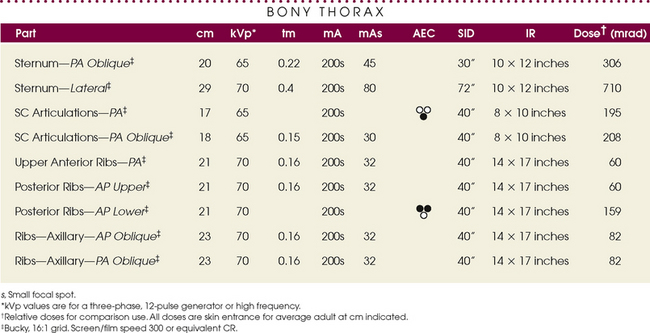
Fig. 1-44 Radiographic exposure technique chart showing manual and AEC technical factors for the examinations identified.
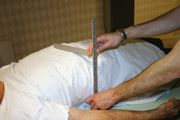
Fig. 1-45 Measuring caliper is used to measure the body part for accurate exposure technique selection.
Each chapter contains a sample exposure technique chart of the essential projections described in the chapter. This chart is a sample only, and the exposure techniques listed should not be used unless all the technical parameters are exactly the same in the user’s department. The chart can be used, however, to show typical manual and automatic exposure techniques and the difference between exposures for various body parts and to serve as a baseline for developing accurate charts for a radiology department. The kVp values for each projection are approximate for the three-phase generator used for the charts and can be used for the body part as indicated.
A satisfactory technique chart can be established only by the radiographer’s familiarity with the characteristics of the particular equipment and accessories used and the radiologist’s preference in image quality. The following primary factors must be taken into account when the correct foundation technique is being established for each unit:
• Automatic exposure controls (AECs)
• Source–to–image receptor distance (SID)
With this information available, the exposure factors can be selected for each region of the body and balanced so that the best possible radiographic quality is obtained.
Modern x-ray generators have anatomic programmers that can store a wide range of radiographic exposure techniques for most body parts (Fig. 1-46). The radiographer simply selects the body part, and the technique is automatically set.
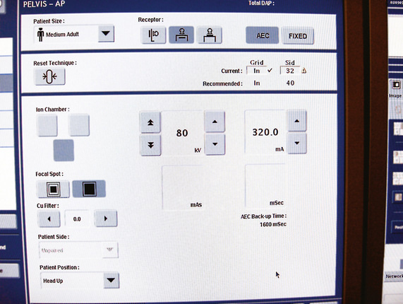
Adaptation of Exposure Technique to Patients
The radiographer’s responsibility is to select the combination of exposure factors that produces the desired quality of radiographs for each region of the body and to standardize this quality. When the radiographer establishes this standard quality, deviation from the exposure factors should be minimal. These foundation factors should be adjusted for every patient’s size to maintain uniform quality. The same definition on all subjects cannot be achieved, however, because of congenital and developmental factors and age and pathologic changes. Some patients have fine, distinct bony trabecular markings, whereas others do not. Individual differences must be considered when the quality of the radiograph is judged.
Certain conditions require the radiographer to compensate when establishing an exposure technique (Fig. 1-47). Conditions that require a decrease in technical factors include the following:
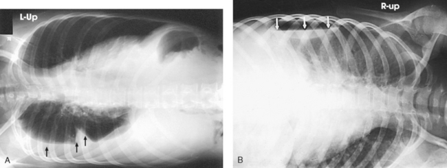
Fig. 1-47 A, Right lateral decubitus chest radiograph showing fluid level (arrows). The radiographic exposure technique had to be increased from the standard technique to show the fluid level. B, Left lateral decubitus chest radiograph showing air-fluid level (arrows). The radiographic exposure technique had to be decreased from the standard technique to show the free air.
Some conditions require an increase in technical factors to penetrate the part to be examined. These include the following:
Preexposure Instructions
The radiographer should instruct the patient in breathing and have the patient practice until the necessary actions are clearly understood. After the patient is in position but before the radiographer leaves to make the exposure, the radiographer should have the patient practice breathing once more. This step requires a few minutes, but it saves much time and the need for repeat radiographs.
Inspiration (inhalation) depresses the diaphragm and abdominal viscera, lengthens and expands the lung fields, elevates the sternum and pushes it anteriorly, and elevates the ribs and reduces their angle near the spine. Expiration (exhalation) elevates the diaphragm and abdominal viscera, shortens the lung fields, depresses the sternum, and lowers the ribs and increases their angle near the spine.
During trunk examinations, the patient’s phase of breathing is important. When exposures are to be made during shallow breathing, the patient should practice slow, even breathing, so that only the structures above the one being examined move. When lung motion and not rib motion is desired, the patient should practice slow, deep breathing after a compression band has been applied across the chest. (The correct respiration phase is printed in the positioning instructions for each projection in the text.)
The eyes of the radiographer should always be on the patient when the exposure is made to ensure that an exposure is not made if the patient moves or breathes. This is particularly important when radiographing pediatric, trauma, unconscious, and some geriatric patients.
Technical Factors
The variation in power delivered by the x-ray tube permits the radiographer to control several prime technical factors: milliamperage (mA), kilovolt peak (kVp), and exposure time (seconds). The radiographer selects the specific factors required to produce a quality radiograph using the generator’s control panel after consulting a technique chart. Manual and AEC systems are used to set the factors (Fig. 1-48).
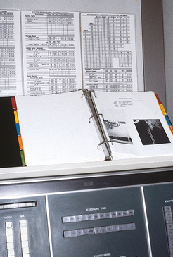
Fig. 1-48 X-ray generator control panel where exposure factors are set. Also note exposure technique chart on the wall. Radiographer uses the chart to set the techniques for each projection performed.
Detailed aspects of each technical factor are presented in physics and imaging courses. Because of the variety of exposure factors and equipment used in clinical practice, exact technical factors are not presented in this atlas. The companion Merrill’s Pocket Guide to Radiography is designed to allow students and radiographers to organize and write in the technical factors used in respective departments with the different equipment available (Fig. 1-49). Each chapter’s technique chart shows an approximate kVp and AEC detector setting as described later. These two parameters do not vary from department to department. The factors mA, exposure time, SID, screens, grids, CR and DR factors are highly variable, however, and not listed.
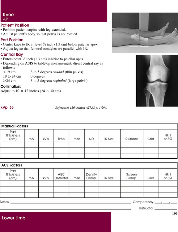
Fig. 1-49 Exposure technique page from Merrill’s Pocket Guide to Radiography showing how a specific department’s manual techniques and AEC techniques can be written in for reference in setting optimal techniques. Note also patient photograph and radiograph. Quick reference can be made to the exact position of the patient, and the radiograph shows how the final image should appear.
KILOVOLTAGE IN THIS ATLAS
The kVp setting is a crucial factor that controls the energy and penetrating ability of the x-ray beam. Various kVp settings are used depending on the type of x-ray generators used, the type of grid used, and the contrast of the finished radiograph. A 70-kVp technique with a three-phase generator requires 80 kVp with a single-phase generator to maintain the same contrast level.1 An approximate kVp value is shown for each essential projection for three-phase generators. These are the kVp values that ensure an adequate penetration of the body part and appropriate dose control.
AUTOMATIC EXPOSURE CONTROL IN THIS ATLAS
X-ray generators contain complex AEC systems that require several settings for each exposure—kVp, mA, backup timer, density control, screen setting, and sensor selection. Numerous factors, including the type of examination, tabletop or Bucky technique, patient cooperation, and cassette size, determine which settings are used. For projections that are performed using AEC, an approximate detector selection is shown in the text for each essential projection. The other AEC variables are not shown because of the wide range of settings used in radiology departments (see Fig. 1-49).
Working Effectively with Obese Patients
Radiology departments are having a difficult time acquiring and interpreting images of obese patients. A study found the number of radiology studies that were difficult to interpret because of obesity has doubled over the last 15 years.1 According to the CDC, approximately 64% of Americans are overweight, obese, or morbidly obese.2 More than 72 million adults are obese, and more than 6 million are morbidly obese (Fig. 1-50). The prevalence of obesity in children has been steadily increasing. Over the past 25 years, the number of obese children has nearly tripled. Approximately 15% of children 6 to 9 years old are obese.3 Obesity has an impact on the quality of the radiographic image, and it affects the radiographer’s ability to transfer and position the patient. Obese patients have an effect on the functionality of the imaging equipment, and many obese patients cannot be placed onto radiographic or computed tomographic (CT) tables. Meanwhile, the popularity of bariatric surgery has increased the demand for radiographic procedures in obese patients.
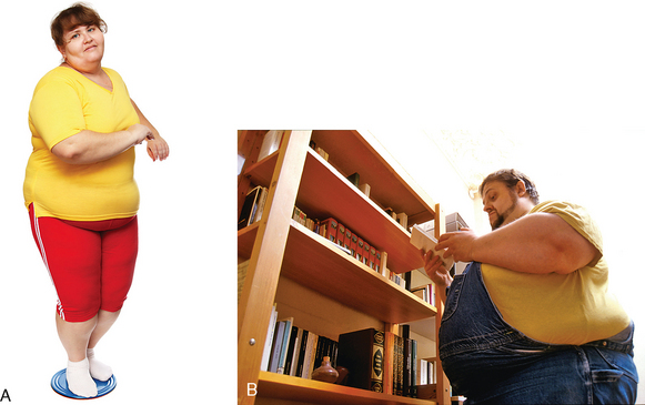
Fig. 1-50 A, Obese patient. B, Morbidly obese patient. (A, Used with permission from Fotosearch; B, Copyright Phototake, Inc.)
Obesity is defined as an increase in body weight by excessive accumulation of fat. More specifically, obesity is quantified by the body mass index (BMI).1 A BMI of 30 to 39.9 is classified as obese. A BMI greater than 40 is classified as morbidly obese, or approximately 100 lb overweight. The BMI is not of primary importance when performing radiographic examinations; the patient’s body diameter and weight are the two important considerations. One or both of these factors determine whether or not a radiographic examination can be performed.
EQUIPMENT
Manufacturers of imaging equipment have defined weight limits. The structural integrity and function of equipment and motors are typically insured by manufacturers up to the stated weight only. Radiographic table weight limits cannot be exceeded without voiding the warranty. Fluoroscopy towers have a maximum diameter, and many obese patients cannot fit under the tower. CT and magnetic resonance imaging (MRI) scanners have gantry and bore diameters that cannot accommodate some obese patients. Table 1-6 lists the current industry standard weight limits and maximum aperture diameters. For CT and MRI, the aperture diameter is accurate in the horizontal plane. The vertical plane must take into consideration the table thickness entering the gantry or bore. The table takes up 15 to 18 cm of the stated vertical diameter; this limits many patients from having CT or MRI examinations. Most radiology departments do not perform examinations on patients who weigh more than 350 to 450 lb. Radiographers must be aware of the weight and aperture limits of the radiographic equipment in their departments. The radiology department should have a protocol for working with obese patients, and all equipment should be marked with the limits.
TABLE 1-6
Industry standard weight limit and maximum aperture diameter by imaging technique
| Imaging technique | Weight limit | Maximum aperture diameter (cm) |
| Fluoroscopy | 350 lb (159 kg) | 45 |
| 4- to 16-multidetector CT | 450 lb (205 kg) | 70* |
| Cylindric bore MRI, 1.5-3.0 T | 350 lb (159 kg) | 60* |
| Vertical field MRI, 0.3-1.0 T | 550 lb (250 kg) | 55* |
*Aperture is accurate in horizontal plane only. For vertical plane, about 15 to 18 cm must be subtracted from diameter to account for table thickness.
To accommodate obese patients, most radiography equipment manufacturers are redesigning their equipment and increasing table weights and aperture dimensions. Table 1-7 shows the limits of the current equipment that has been modified for obese patients. Radiographic and fluoroscopic table weight limits have doubled to 700 lb. CT and MRI table weights and aperture openings have also increased.
TABLE 1-7
Advances in weight limit and maximum aperture diameter by imaging technique
| Imaging technique | Weight limit | Maximum aperture diameter (cm) |
| Fluoroscopy | 700 lb (318 kg) | 60 |
| 16-multidetector CT | 680 lb (308 kg) | 90* |
| Cylindric bore MRI, 1.5 T | 550 lb (250 kg) | 70* |
| Vertical field MRI, 0.3-1.0 T | 550 lb (250 kg) | 55* |
*Aperture is accurate in horizontal plane only. For vertical plane, about 15 to 18 cm must be subtracted from diameter to account for table thickness.
TRANSPORTATION
Transportation of obese patients is another way in which obesity affects the delivery of health care to these individuals. Obese patients require larger wheelchairs and larger transport beds or stretchers. Some hospitals have installed larger doorways to accommodate the larger transportation equipment. The availability of these special chairs and beds may be limited and may affect the scheduling of these patients. One manufacturer1 has designed a special cart that can hold patients weighing 750 lb; this cart has a 34-inch pad width. Many obese patients, unless they are hospitalized, are able to walk around and access clinics and imaging centers. Their weight becomes an issue, however, when they have to get on the radiographic equipment.
A major factor involved in the transportation and transfer of obese patients is the potential risk of injury to the radiographer and other health care workers during movement and positioning of patients. Radiographic examinations of obese patients who are hospitalized must be coordinated carefully between the radiology department and the patient’s nursing section. Appropriate measurements must be made in the patient’s room in advance by trained radiology personnel. An obese patient should not be transported to the radiology department and find on arrival that he or she cannot be accommodated.
An appropriate number of staff must be available to ensure that there is appropriate moving assistance. Transfer of a patient from the cart to the radiographic table may require 8 to 10 individuals. Obese patients are not lifted; they are moved by sliding. Hydraulic lifts cannot be used because of weight limit restrictions, and most obese patients are too large or wide for plastic moving devices and sliders. It is imperative that proper body mechanics be used by all personnel moving these patients.
COMMUNICATION
Communication with obese patients may require personnel to be more aware of the issues of obesity. The radiographer must be able to assess the difficulties created by the limitations of equipment in handling an obese patient and be able to communicate with the patient without offending him or her. The dignity of the patient must be kept in mind. Sensitivity training should be provided by the hospital or clinic. For the most part, communications are no different than with a nonobese patient. Reference to the patient’s weight should never be made. The radiographer should be sensitive and display compassion. This can be accomplished by clearly explaining the procedure to gain the patient’s confidence and trust. After the patient’s trust and cooperation have been obtained, it is easier to communicate effectively if any problems or concerns with the examination arise.
There should never be any discussion about the patient in the radiographic room and no discussion within hearing distance of the patient about the poor image quality or the difficulty in obtaining images. If the radiologist and the patient’s physician together determine that the patient’s weight allows radiographic images to be made, the examination should proceed in the same manner as with any other patient. More staff may be needed for transfer purposes; however, communications and performance of the examination should remain the same.
IMAGING CHALLENGES
When the patient is on the table, it is imperative that he or she is centered accurately to the center of the table; this is necessary because it may be impossible to palpate traditional landmarks such as the anterior-superior iliac spine (ASIS) and iliac crest (see Chapter 3 for positioning landmarks). One of the most important considerations in positioning an obese patient is to recognize that the bony skeleton and most organs have not changed in position and the organs are not larger. Most of what is seen physically on these patients is fat. In Fig. 1-51, the skeleton is normal size, and most organs fall with their normal position. The only exception would be in morbidly obese patients, in whom the width of the thoracic cage and ribs may be expanded 2 inches, the stomach may be slightly larger, and the colon may be spread out more across the width of the abdomen. Most positioning landmarks used on obese patients will be reference points in the midsagittal plane of the patient.
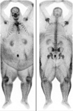
Fig. 1-51 Bone scan on 500-lb patient. Note large physical size of patient, but within the large body are the skeleton and organs of a typical 165-lb body. (Used with permission from ARRS.)
Radiographic projections of the skull, cervical spine, and upper limb are obtainable on all obese patients. Projections of the lower limb from the knee distally are obtainable. Shoulder and femur projections may be difficult to position but are usually obtainable. All projections of the thorax including lungs, abdomen, thoracic and lumbar spines, pelvis, and hips are very challenging to position and may be impossible to obtain in morbidly obese patients. The patient’s lack of mobility makes lateral hip projections virtually impossible. Fig. 1-52 shows that most fat accumulates around the trunk, particularly around the abdomen, pelvis, and hips. Imaging of organs such as the stomach, small bowel, and colon may be impossible. CT may be the only imaging alternative, if the equipment integrity can support the weight and girth of these patients.
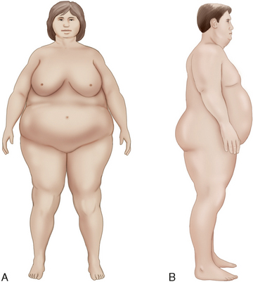
Fig. 1-52 Large amount of body fat that surrounds the abdomen, pelvis, hips, and upper femora on obese patients. Dimensions shown are from actual patient measurements.
Landmarks
Finding traditional positioning landmarks may be possible in some obese patients and impossible in morbidly obese patients. It is appropriate to enlist the patient’s assistance in identifying landmarks if it is possible. This gives the patient a sense of being involved in their examination. The jugular notch may be the only landmark available for palpation. Traditional landmarks such as the xiphoid, ASIS, iliac crest, pubic symphysis, and greater trochanter are impossible to palpate. The radiographer should not attempt to push and prod to find these. Fig. 1-53 shows a morbidly obese patient and how he would appear on the radiographic table. The traditional landmarks would be impossible to find because of excess body fat. If the patient’s chin is raised, however, the jugular notch can be palpated.
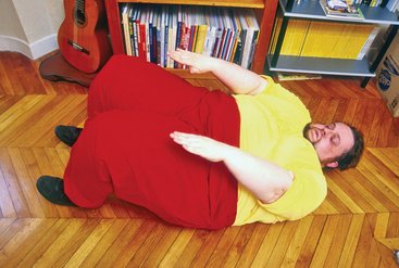
Fig. 1-53 Morbidly obese patient. Traditional landmarks would be impossible to palpate. With the chin raised, the jugular notch can be palpated. (Copyright Phototake, Inc.)
The importance of the jugular notch cannot be underestimated because most projections of the thorax, abdomen, and pelvis can be obtained by simply finding this landmark. Two items should be available in the radiographic room—tongue depressors and a tape measure. When the jugular notch is found, a tongue depressor should be placed on the notch. With the tape, the radiographer measures straight down the midsagittal plane, from the jugular notch point to the pubic symphysis (Fig. 1-54). The symphysis is found at the following distances from the jugular notch:
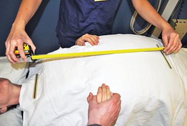
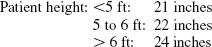
At the point of the pubic symphysis, the second tongue depressor is placed. The two depressors presents a visual indication of the trunk of the body. Note the symphysis will not be palpated due to the pendiculum (the fat skirt that hangs down over the symphysis). The indicators above will determine its location. When the radiographer knows where these two anatomic points are, nearly all projections of the trunk can be obtained with moderate accuracy. The bottom edge of a 14- × 17-inch (35- × 43-cm) IR placed lengthwise at the pubic symphysis shows the abdomen and lumbar spine. If the bottom edge of the IR is placed crosswise, it shows the pelvis and hips. The first thoracic vertebra (T1) is located approximately 2 inches (5 cm) above the jugular notch. An understanding of the landmarks related to body structures described in Chapter 3 enables the radiographer to position for nearly all projections of the trunk.
Some variations in obese patients occur. Many of these patients have a very large abdomen only (Fig. 1-55). Although their other body areas are not large, the largeness of the abdomen prevents any type of landmark palpation for lumbar spine, abdomen, and pelvis images. In other obese patients, the abdominal fat is very soft and movable and is layered in “folds” (Fig. 1-56). For these patients, the radiographer can gently move or push the folds of skin out of the way to palpate the ASIS or iliac crest. The patient should be informed of what the radiographer is doing every step of the way.
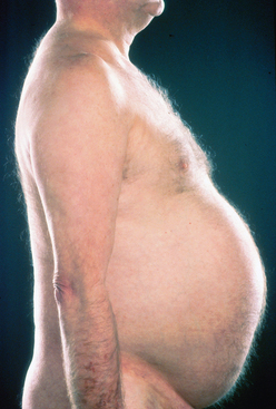
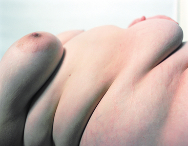
Oblique and lateral projections
Caution should be used when turning patients on their side for oblique and lateral projections. Turning should always be done with the assistance of the patient and at least three other health care workers. Positioning aids or equipment should be used to prevent injury to the patient and personnel. Before turning the patient, measurements should be taken of the body part width to determine if the exposure technique can be made. Oblique and lateral projections of the hips, lumbar spine, lumbosacral area, sacrum, coccyx and, in some patients, thoracic spine may be prohibited because of x-ray tube limits (Fig. 1-57). The patient should not be turned unless the exposure can be made. Oblique and lateral projections are typically impossible to obtain on a morbidly obese patient. “Cross-table” projections also may be impossible because of the patient’s size and the very large amount of scatter radiation produced. Lower grid ratios ingrid holders are typically used for these exposures, and these do not aid in improving the image quality. There may be limited instances when two exposures can be made. The patient must be able to cooperate, however, and this works only on bone projections.
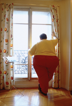
Image receptor sizes and collimation
At first, it may seem that larger size IRs are needed to image obese patients. In most instances, this is not the case. If care is taken to find landmarks, in particular, the jugular notch and pubic symphysis, relatively accurate positioning can be accomplished. Collimation is one of the most important considerations when imaging obese patients. Setting the collimator to the smallest dimensions possible reduces scatter radiation. The reduced scatter increases contrast, which enables improved visibility of the structures (Fig. 1-58). The use of standard size IRs and standard collimation settings for DR keeps scatter radiation to low levels, and scatter radiation fog on the image is reduced. The collimator should never be set larger than the size of the IR.
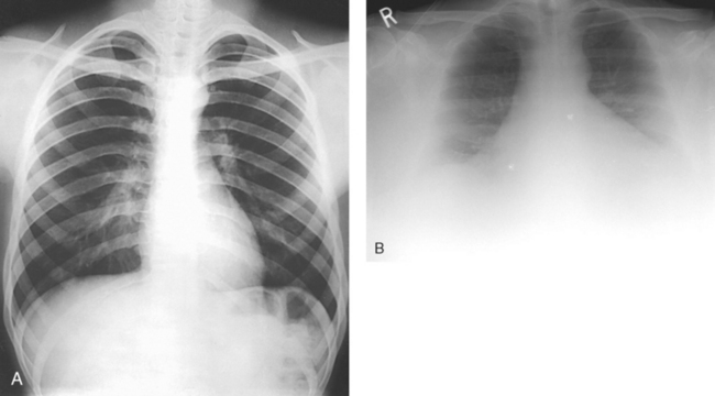
Fig. 1-58 A, Chest radiograph on 160-lb patient. Note very good contrast and visibility of structures. B, Chest radiograph on 500-lb patient. Note reduced contrast and fogging on image. A reasonable image was obtained, however. (B, Used with permission from ARRS.)
Digital radiography: With DR and the availability of the 17- ×17-inch (43- × 43-cm) flat-panel detector built in the table (see Fig. 1-31, D), there may be a temptation to use the maximum size of this field on the large patients. This temptation should be avoided. This very large collimator setting produces more scatter, increases fog on the radiograph, and reduces contrast. Collimating larger than the traditional 14 × 17 inches (35 × 43 cm) for the body parts that require this dimension images only more fat. Recall from Fig. 1-51 that within the large body is a standard size skeletal frame and organs. A significantly improved diagnostic image is obtained on obese patients when smaller IRs and collimation settings are used. For colon and other abdominal images, it may be necessary to take multiple images on quadrants of the body1 using smaller collimation settings. When using DR to image obese patients, radiographers should use the collimation settings for the various projections as indicated in this atlas.
Field light size: When the collimator size is set automatically for IRs in the Bucky or manually on the collimator for DR equipment, the field light is visible on a nonobese patient’s body relatively close to the actual dimensions of the IR (Fig. 1-59, A). This light gives the radiographer an accurate visual indication of where the radiation field falls. On obese patients, in whom the vertical dimension of the thorax and abdomen is very large (see Fig. 1-50, B), the field light visible on top of the patient appears much smaller than the IR size because the abdomen is closer to the collimator bulb, and less light divergence occurs (Fig. 1-59, B). There may be a natural tendency to open the collimator when this small field is seen. The collimator should not be opened larger than the size of the IR or the stated collimator dimensions for DR. The radiographer must understand that although the field size visually appears small on top of the patient, the radiation field diverges to expose the entire IR size.
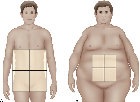
Fig. 1-59 A, Illustration of how collimator light for 14- × 17-inch (43- × 43-cm) IR appears on normal-size patient with 21-cm abdomen measurement. The light is very close in dimension to IR size. B, Collimator light shown for same size IR on obese patient with 45-cm vertical abdomen measurement. Although collimator is set to same dimensions, light field appears small on top of the patient.
EXPOSURE FACTORS
Modified x-ray exposure techniques need to be used on obese patients. The main factors have to be increased, including the mA, kVp, and exposure time. The major limitation in obtaining images of obese patients is inadequate penetration of the body part. This situation results in increased quantum mottle (noise) and very low image contrast. The increased exposure time required in these patients can also contribute to motion artifacts in the image. The most important adjustment that should be made is an increase in the kVp. Increasing the kVp increases the penetration of the x-ray beam. The mA and exposure time (mAs) have to be increased; however, caution should be used in increasing the mA. Greater exposures can be obtained safely by using low mA settings and longer exposure times. (See tube rating charts in a physics text.)
Motion is not a major problem in imaging obese patients because the weight of the patient prevents most body parts from moving, and mA settings of about 320 can be used. This setting may increase the exposure time; however, with an explanation of the importance of holding the breath, most obese patients can do so. With repeated use of high exposure factors, the x-ray tube can become very hot. Radiographers should ensure that adequate cooling of the anode and tube as a whole occurs; this can be accomplished by simply taking more time in between exposures.
Focal spot
The focal spot in the x-ray tube is controlled by the mA that is selected. The mA for obese patient radiographs may be higher than 250 to 320 mA, which will automatically engage the large focus. Use of the small focal spot, which enables greater recorded detail, may be restricted to the distal limbs because of the higher exposure techniques. Radiographers must have a full understanding of the focal spot limits for the machines they use. These should be posted for use with obese patient projections.
Bucky and grid
The use of a Bucky grid or a mobile grid can minimize scatter radiation significantly. The grid is automatically used when obtaining standard projections on the x-ray table and for some cross-table lateral images of limbs. Although a grid is never used for elbow, ankle, and leg projections on nonobese patients, it can significantly improve image quality on obese patients and in particular morbidly obese patients. Radiology departments should have a high-ratio mobile grid available for use with obese patients.
Automatic exposure control and anatomically programmed radiography systems
AEC and anatomically programmed radiography (APR) systems are widely used in radiology departments to control technical factors “automatically.” Machine-set exposure factors will frequently be inappropriate for obese patients so the kVp, mA, exposure time, AEC detectors, and focal spot should be manually adjusted. With AEC, the radiographer should ensure that a high kVp and a moderate mA are used. The radiology department should maintain a special exposure technique chart for obese patients similar to using a special chart for pediatric patients. When possible, all three AEC detectors should be activated.
Mobile radiography
Mobile radiography machines may be used for imaging obese patients; however, their use is very limited. Because the x-ray tubes on these machines have limited ratings, exposure techniques high enough to penetrate these patients cannot be obtained. Depending on the size of the patient, mobile projections are restricted to chest and limbs only. The mobile machine should have a special technique chart outlining the technical factors used for this group of patients.
Radiation dose
Radiographers must use caution in all aspects of working with obese patients, including keeping repeat exposures to a minimum. A study of radiation doses to obese patients having bariatric surgery showed a “fourfold” dose increase compared with nonobese patients having the same examinations.1 Doses to these patients reached 4500 mrem (45 mSv). Precautions must be taken to minimize patient dose. The radiologist should be involved in evaluating the justification of any radiologic procedure on an obese patient. Radiographers should be especially cautious when holding a limb or an IR during an x-ray exposure on an obese patient. The increased exposure techniques prompt increased scatter, which reaches the person holding the patient. If some-one has to hold an obese patient, when possible, the person should stand at a right angle (90 degrees) to the central ray for maximum scatter protection. (See Mobile Chapter 28 for further information.)
Special technical considerations must be followed when working with obese and morbidly obese patients. Box 1-4 summarizes the principal technical factors that should be observed.
1Code of ethics, ASRT, February 2003.
2CAMRT, Approved, June 2008.
1The Joint Commission, Oakbrook Terrace, IL.
1Age-specific competence, Oakbrook Terrace, IL, 1998, The Joint Commission.
2Assessing hospital staff competence, Oakbrook Terrace, IL, 2002, The Joint Commission.
1Eastman TR: Digital systems require x-ray charts too, Radiol Technol 67:354, 1996.
2Eastman TR: X-ray film quality and national contracts, Radiol Technol 69:12, 1997.
3Gray JE et al: Quality control in diagnostic imaging, Rockville, MD, 1983, Aspen.
4Kebart RC, James CD: Benefits of increasing focal film distance, Radiol Technol 62:434, 1991.
5Brennan PC, Nash M: Increasing SID: an effective dose-reducing tool for lateral lumbar spine investigations, Radiography 4:251, 1998.
6Carlton RR, Adler AM: Principles of radiographic imaging, ed 4, Albany, NY, 2006, Thomson Delmar Learning.
1National Council on Radiation Protection: NCRP Report 102, Bethesda, MD, 1989, The Council.
1Bureau of Radiological Health: Gonad shielding in diagnostic radiology, Pub No. (FDA) 75-8024, Rockville, MD, 1975, The Bureau.
1Eastman TR: Digital systems require x-ray charts too, Radiol Technol 67:354, 1996.
2Gray JE et al: Quality control in diagnostic imaging, Rockville, MD, 1983, Aspen.
3Eastman TR: Get back to the basics of radiography, Radiol Technol 68:285, 1997.
1Cullinan AM, Cullinan JE: Producing quality radiography, Philadelphia, 1994, JB Lippincott.
1Trenker SW: Imaging of morbid obesity procedures and their complications, Abdominal Imaging 34:335, 2008.
2Department of Health and Human Services, Centers for Disease Control and Prevention: Overweight and obesity: obesity trends: 1991–2001 prevalence of obesity among U.S. adults by state-behavioral risk factor surveillance system 2001, Available at: www.cdc.gov/nccdphp/dnpa/obesity/trend/prev_reg.htm.
3Choudhary AK et al: Diseases associated with childhood obesity, AJR Am J Roentgenol 188:1118, 2007.
1Uppot RN et al: Impact of obesity on medical imaging and image-guided intervention, AJR Am J Roentgenol 188:433, 2007.
1Pedigo, Vancouver, WA, Available at: www.pedigo.com. Accessed April 1, 2010.
1Uppot RN et al: Impact of obesity on medical imaging and image-guided intervention, AJR Am J Roentgenol 188:433, 2007.
1Rampado O et al: Radiation dose evaluations during radiological contrast studies in patients with morbid obesity, Radiol Med 113:1229, 2008.