THORACIC VISCERA
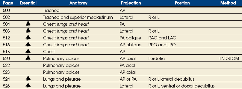
SUMMARY OF PROJECTIONS
Body Habitus
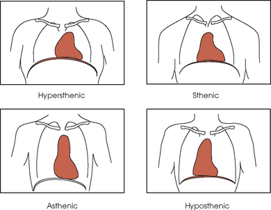
The general shape of the human body, or the body habitus, determines the size, shape, position, and movement of the internal organs. Fig. 10-1 outlines the general shape of the thorax in the four types of body habitus and how each appears on radiographs of the thoracic area.
Thoracic Cavity
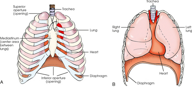
The thoracic cavity is bounded by the walls of the thorax and extends from the superior thoracic aperture, where structures enter the thorax, to the inferior thoracic aperture. The diaphragm separates the thoracic cavity from the abdominal cavity. The anatomic structures that pass from the thorax to the abdomen go through openings in the diaphragm (Fig. 10-2).
The thoracic cavity contains the lungs and heart; organs of the respiratory, cardiovascular, and lymphatic systems; the inferior portion of the esophagus; and the thymus gland. Within the cavity are three separate chambers: a single pericardial cavity and the right and left pleural cavities. These cavities are lined by shiny, slippery, and delicate serous membranes. The space between the two pleural cavities is called the mediastinum. This area contains all the thoracic structures except the lungs and pleurae.
Respiratory System
The respiratory system consists of the pharynx (described in Chapter 15 in Volume 2), trachea, bronchi, and two lungs. The air passages of these organs communicate with the exterior through the pharynx, mouth, and nose, each of which, in addition to other described functions, is considered a part of the respiratory system.
TRACHEA
The trachea is a fibrous, muscular tube with 16 to 20 C-shaped cartilaginous rings embedded in its walls for greater rigidity (Fig. 10-3, A). It measures approximately ½ inch (1.3 cm) in diameter and 4½ inches (11 cm) in length, and its posterior aspect is flat. The cartilaginous rings are incomplete posteriorly and extend around the anterior two thirds of the tube. The trachea lies in the midline of the body, anterior to the esophagus in the neck. In the thorax, the trachea is shifted slightly to the right of the midline as a result of the arching of the aorta. The trachea follows the curve of the vertebral column and extends from its junction with the larynx at the level of the sixth cervical vertebra inferiorly through the mediastinum to about the level of the space between the fourth and fifth thoracic vertebrae. The last tracheal cartilage is elongated and has a hooklike process, the carina, which extends posteriorly on its inferior surface. At the carina, the trachea divides, or bifurcates, into two lesser tubes—the primary bronchi. One of these bronchi enters the right lung, and the other enters the left lung.
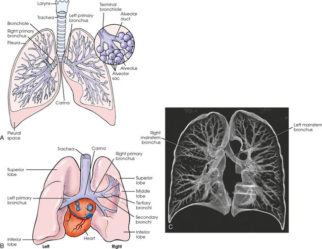
Fig. 10-3 A, Anterior aspect of respiratory system. B, Posterior aspect of heart, lungs, trachea, and bronchial trees. C, Coronal, three-dimensional CT image of central and peripheral airways. (C, From Kelley LL, Petersen CM: Sectional anatomy for imaging professionals, ed 2, St Louis, 2007, Mosby.)
The primary bronchi slant obliquely inferiorly to their entrance into the lungs, where they branch out to form the right and left bronchial branches (Fig. 10-3, B). The right primary bronchus is shorter, wider, and more vertical than the left primary bronchus. Because of the more vertical position and greater diameter of the right main bronchus, foreign bodies entering the trachea are more likely to pass into the right bronchus than the left bronchus.
After entering the lung, each primary bronchus divides, sending branches to each lobe of the lung: three to the right lung and two to the left lung. These secondary bronchi divide further and decrease in caliber. The bronchi continue dividing into tertiary bronchi, then to smaller bronchioles, and end in minute tubes called the terminal bronchioles (see Fig. 10-3). The extensive branching of the trachea is commonly referred to as the bronchial tree because it resembles a tree trunk (see box).
ALVEOLI
The terminal bronchioles communicate with alveolar ducts. Each duct ends in several alveolar sacs. The walls of the alveolar sacs are lined with alveoli (see Fig. 10-3, A). Each lung contains millions of alveoli. Oxygen and carbon dioxide are exchanged by diffusion within the walls of the alveoli.
LUNGS
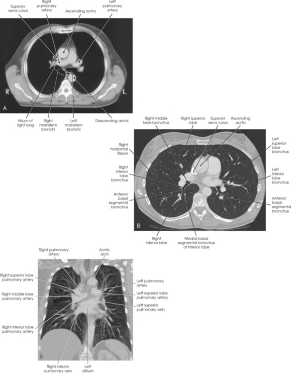
The lungs are the organs of respiration (Fig. 10-4). They are the mechanism for introducing oxygen into the blood and removing carbon dioxide from the blood. The lungs are composed of a light, spongy, highly elastic substance, the parenchyma, and they are covered by a layer of serous membrane. Each lung presents a rounded apex that reaches above the level of the clavicles into the root of the neck and a broad base that, resting on the obliquely placed diaphragm, reaches lower in back and at the sides than in front. The right lung is about 1 inch (2.5 cm) shorter than the left lung because of the large space occupied by the liver, and it is broader than the left lung because of the position of the heart. The lateral surface of each lung conforms with the shape of the chest wall. The inferior surface of the lung is concave, fitting over the diaphragm, and the lateral margins are thin. During respiration, the lungs move inferiorly for inspiration and superiorly for expiration (Fig. 10-5). During inspiration, the lateral margins descend into the deep recesses of the parietal pleura. In radiology, this recess is called the costophrenic angle (see Fig. 10-5, B). The mediastinal surface is concave with a depression, called the hilum, that accommodates the bronchi, pulmonary blood vessels, lymph vessels, and nerves. The inferior mediastinal surface of the left lung contains a concavity called the cardiac notch. This notch conforms to the shape of the heart.
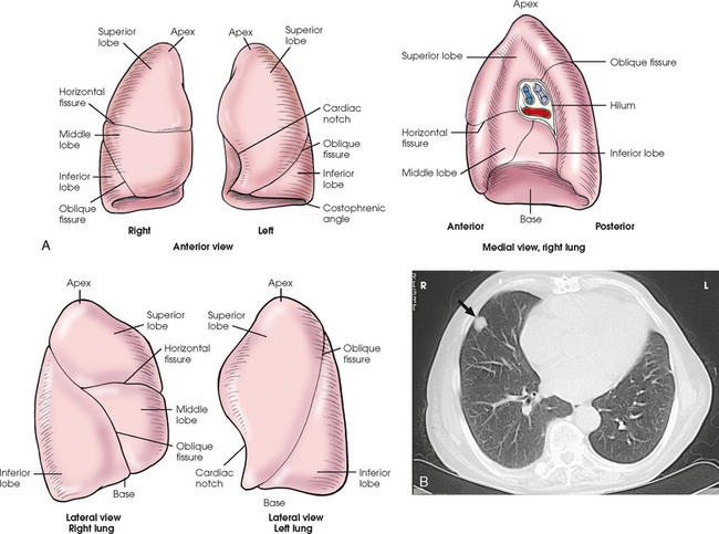
Fig. 10-4 A, Three views of the lung. B, CT axial image through the thorax. Right and left lungs are shown in actual position within thorax and in relation to heart. Note nodule in right anterior lung (arrow). (B, Courtesy Siemens Medical Systems, Iselin, NJ.)
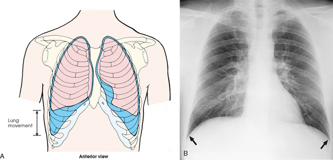
Fig. 10-5 A, Movement of lungs during inspiration and expiration. B, Costophrenic angles shown (arrows) on PA projection of chest.
Each lung is enclosed in a double-walled, serous membrane sac called the pleura (see Fig. 10-3, A). The inner layer of the pleural sac, called the visceral pleura, closely adheres to the surface of the lung, extends into the interlobar fissures, and is contiguous with the outer layer at the hilum. The outer layer, called the parietal pleura, lines the wall of the thoracic cavity occupied by the lung and closely adheres to the upper surface of the diaphragm. The two layers are moistened by serous fluid so that they move easily on each other. The serous fluid prevents friction between the lungs and chest walls during respiration. The space between the two pleural walls is called the pleural cavity. Although the space is termed a cavity, the layers are actually in close contact.
Each lung is divided into lobes by deep fissures. The fissures lie in an oblique plane inferiorly and anteriorly from above, so that the lobes overlap each other in the AP direction. The oblique fissures divide the lungs into superior and inferior lobes. The superior lobes lie above and are anterior to the inferior lobes. The right superior lobe is divided further by a horizontal fissure, creating a right middle lobe (see Fig. 10-4). The left lung has no horizontal fissure and no middle lobe. The portion of the left lobe that corresponds in position to the right middle lobe is called the lingula. The lingula is a tongue-shaped process on the anteromedial border of the left lung. It fills the space between the chest wall and the heart.
Each of the five lobes divides into bronchopulmonary segments and subdivides into smaller units called primary lobules. The primary lobule is the anatomic unit of lung structure and consists of a terminal bronchiole with its expanded alveolar duct and alveolar sac.
Mediastinum
The mediastinum is the area of the thorax bounded by the sternum anteriorly, the spine posteriorly, and the lungs laterally (Fig. 10-6). The structures associated with the mediastinum are as follows:
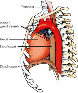
The esophagus is the part of the digestive canal that connects the pharynx with the stomach. It is a narrow, musculomembranous tube about 9 inches (23 cm) in length. Following the curves of the vertebral column, the esophagus descends through the posterior part of the mediastinum and then runs anteriorly to pass through the esophageal hiatus of the diaphragm.
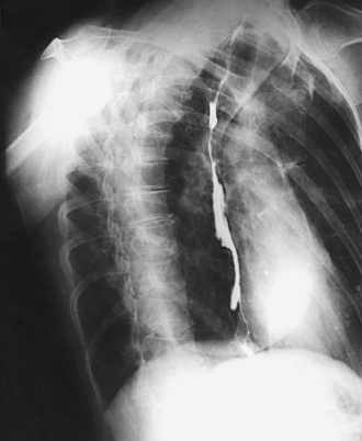
The esophagus lies just in front of the vertebral column, with its anterior surface in close relation to the trachea, aortic arch, and heart. This makes the esophagus valuable in certain heart examinations. When the esophagus is filled with barium sulfate, the posterior border of the heart and aorta are outlined well in lateral and oblique projections (Fig. 10-7). Frontal, oblique, and lateral images are often used in examinations of the esophagus. Radiography of the esophagus is discussed later in this chapter.
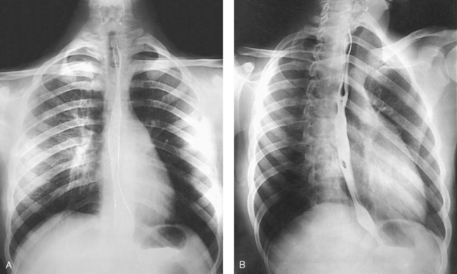
Fig. 10-7 A, PA projection of esophagus with barium sulfate coating its walls. B, PA oblique projection with barium-filled esophagus (RAO position).
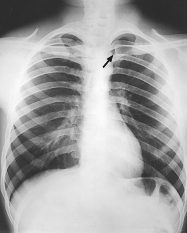
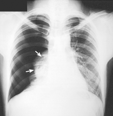
The thymus gland is the primary control organ of the lymphatic system. It is responsible for producing the hormone thymosin, which plays a crucial role in the development and maturation of the immune system. The thymus consists of two pyramid-shaped lobes that lie in the lower neck and superior mediastinum, anterior to the trachea and great vessels of the heart and posterior to the manubrium. The thymus reaches its maximum size at puberty and then gradually undergoes atrophy until it almost disappears (Fig. 10-8).
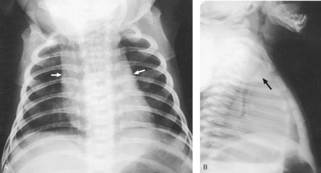
Fig. 10-8 A, PA chest radiograph showing mediastinal enlargement caused by hypertrophy of thymus (arrows). B, Lateral chest radiograph showing enlarged thymus (arrow).
In older individuals, lymphatic tissue is replaced by fat. At its maximum development, the thymus rests on the pericardium and reaches as high as the thyroid gland. When the thymus is enlarged in infants and young children, it can press on the retrothymic organs, displacing them posteriorly and causing respiratory disturbances. A radiographic examination may be made in the AP and lateral projections. For optimal image contrast, exposures should be made at the end of full inspiration.
COMPUTED TOMOGRAPHY
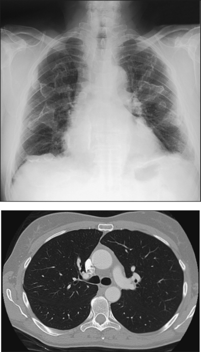
At the present time, computed tomography (CT) is used almost exclusively to image the anatomic areas of the thorax including the thymus gland. CT is excellent at showing all thoracic structures (Fig. 10-9).
SUMMARY OF PATHOLOGY
| Condition | Definition |
| Aspiration/foreign body | Inspiration of a foreign material into the airway |
| Atelectasis | Collapse of all or part of the lung |
| Bronchiectasis | Chronic dilation of the bronchi and bronchioles associated with secondary infection |
| Bronchitis | Inflammation of the bronchi |
| Chronic obstructive pulmonary disease | Chronic condition of persistent obstruction of bronchial airflow |
| Cystic fibrosis | Disorder associated with widespread dysfunction of the exocrine glands, abnormal secretion of sweat and saliva, and accumulation of thick mucus in the lungs |
| Emphysema | Destructive and obstructive airway changes leading to an increased volume of air in the lungs |
| Epiglottitis | Inflammation of the epiglottis |
| Fungal disease | Inflammation of the lung caused by a fungal organism |
| Histoplasmosis | Infection caused by the yeastlike organism Histoplasma capsulatum |
| Granulomatous disease | Condition of the lung marked by formation of granulomas |
| Sarcoidosis | Condition of unknown origin often associated with pulmonary fibrosis |
| Tuberculosis | Chronic infection of the lung caused by the tubercle bacillus |
| Hyaline membrane disease or respiratory distress syndrome | Underaeration of the lungs caused by lack of surfactant |
| Metastases | Transfer of a cancerous lesion from one area to another |
| Pleural effusion | Collection of fluid in the pleural cavity |
| Pneumoconiosis | Lung diseases resulting from inhalation of industrial substances |
| Anthracosis or coal miner’s lung or black lung | Inflammation caused by inhalation of coal dust (anthracite) |
| Asbestosis | Inflammation caused by inhalation of asbestos |
| Silicosis | Inflammation caused by inhalation of silicon dioxide |
| Pneumonia | Acute infection in the lung parenchyma |
| Aspiration | Pneumonia caused by aspiration of foreign particles |
| Interstitial or viral or pneumonitis | Pneumonia caused by a virus and involving the alveolar walls and interstitial structures |
| Lobar or bacterial | Pneumonia involving the alveoli of an entire lobe without involving the bronchi |
| Lobular or bronchopneumonia | Pneumonia involving the bronchi and scattered throughout the lung |
| Pneumothorax | Accumulation of air in the pleural cavity resulting in collapse of the lung |
| Pulmonary edema | Replacement of air with fluid in the lung interstitium and alveoli |
| Tumor | New tissue growth where cell proliferation is uncontrolled |
EXPOSURE TECHNIQUE CHART ESSENTIAL PROJECTIONS
General Positioning Considerations
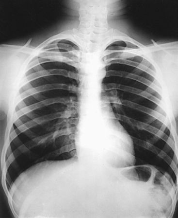
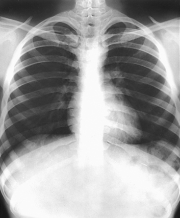
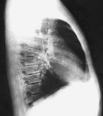
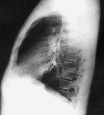
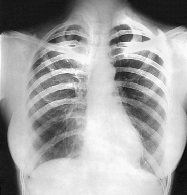
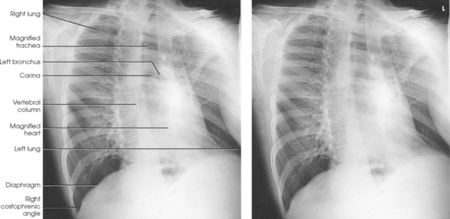
For radiography of the heart and lungs, the patient is placed in an upright position whenever possible to prevent engorgement of the pulmonary vessels and to allow gravity to depress the diaphragm. Of equal importance, the upright position shows air and fluid levels. In the recumbent position, gravitational force causes the abdominal viscera and diaphragm to move superiorly; it compresses the thoracic viscera, which prevents full expansion of the lungs. Although the difference in diaphragm movement is not great in hyposthenic individuals, it is marked in hypersthenic individuals. Figs. 10-10 and 10-11 illustrate the effect of body position in the same patient. The left lateral chest position (Fig. 10-12) is most commonly employed because it places the heart closer to the IR, resulting in a less magnified heart image. Left and right lateral chest images are compared in Figs. 10-12 and 10-13.
A slight amount of rotation from the PA or lateral projections causes considerable distortion of the heart shadow. To prevent this distortion, the body must be carefully positioned and immobilized.
PA CRITERIA
For PA projections, procedures are as follows:
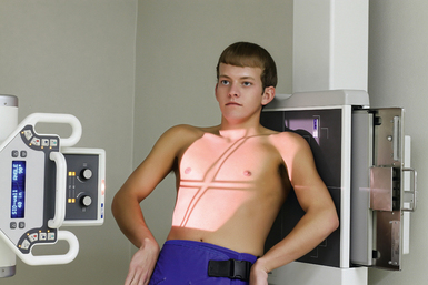
• Instruct the patient to sit or stand upright. If the standing position is used, the weight of the body must be equally distributed on the feet.
• Position the patient’s head upright, facing directly forward.
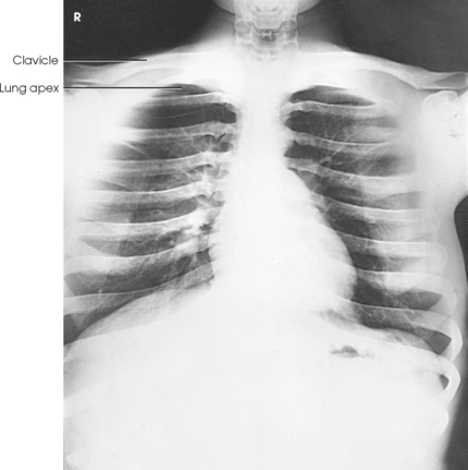
• Have the patient depress the shoulders and hold them in contact with the grid device to carry the clavicles below the lung apices. Except in the presence of an upper thoracic scoliosis, a faulty body position can be detected by the asymmetric appearance of the sternoclavicular joints. Compare the clavicular margins in Figs. 10-14 and 10-15.
LATERAL CRITERIA
For lateral projections, procedures are as follows:
• Place the side of interest against the IR holder.
• Have the patient stand so that the weight is equally distributed on the feet. The patient should not lean toward or away from the IR holder.
• Raise the patient’s arms to prevent the soft tissue of the arms from superimposing the lung fields.
• Instruct the patient to face straight ahead and raise the chin.
• To determine rotation, examine the posterior aspects of the ribs. Radiographs without rotation show superimposed posterior ribs (see Figs. 10-12 and 10-13).
Breathing Instructions
During normal inspiration, the costal muscles pull the anterior ribs superiorly and laterally, the shoulders rise, and the thorax expands from front to back and from side to side. These changes in the height and AP dimension of the thorax must be considered when positioning the patient.
Deep inspiration causes the diaphragm to move inferiorly, resulting in elongation of the heart. Radiographs of the heart should be obtained at the end of normal inspiration to prevent distortion. More air is inhaled during the second breath (and without strain) than during the first breath.
When pneumothorax (gas or air in the pleural cavity) is suspected, one exposure is often made at the end of full inspiration and another at the end of full expiration to show small amounts of free air in the pleural cavity that might be obscured on the inspiration exposure (Figs. 10-16 and 10-17). Inspiration and expiration radiographs are also used to show the movement of the diaphragm, the occasional presence of a foreign body, and atelectasis (absence of air).
Technical Procedure
The projections required to show the thoracic viscera adequately are usually requested by the attending physician and are determined by the clinical history of the patient. The PA projection of the chest is the most common projection and is used in all lung and heart examinations. Right and left oblique and lateral projections are also employed as required to supplement the PA projection. It is often necessary to improvise variations of the basic positions to project a localized area free of superimposed structures.
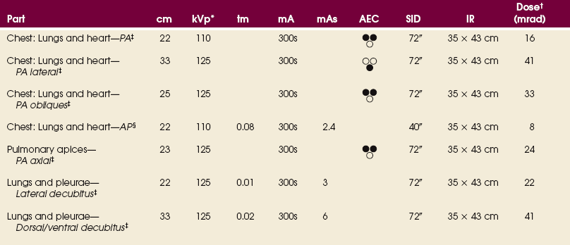
The exposure factors and accessories employed in examining the thoracic viscera depend on the radiographic characteristics of the individual patient’s pathologic condition. Normally, chest radiography uses a high kilovolt (peak) (kVp) to penetrate and show all thoracic anatomy on the radiograph. The kVp can be lowered if exposures are made without a grid.
If the selected kVp is too low, the radiographic contrast may be too high, resulting in few shades of gray. The lung fields may appear properly penetrated on such a radiograph, but the mediastinum appears underexposed. If the selected kVp is too high, the contrast may be too low, and the finer lung markings are not shown. Adequate kVp penetrates the mediastinum and shows a faint shadow of the spine. Whenever possible, a minimum source-to-IR distance (SID) of 72 inches (183 cm) should be used to minimize magnification of the heart and to obtain greater recorded detail of the delicate lung structures (Fig. 10-18). A 120-inch (305-cm) SID is commonly used in radiography of the chest.
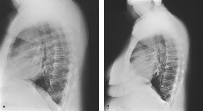
Fig. 10-18 A, Lateral chest radiograph performed at 44-inch (112-cm) SID. B, Radiograph in the same patient performed at 72-inch (183-cm) SID. Note decreased magnification and greater recorded detail of lung structures.
A grid technique is recommended for opaque areas within the lung fields and to show the lung structure through thickened pleural membranes (Figs. 10-19 and 10-20). This technique produces an image with higher contrast.
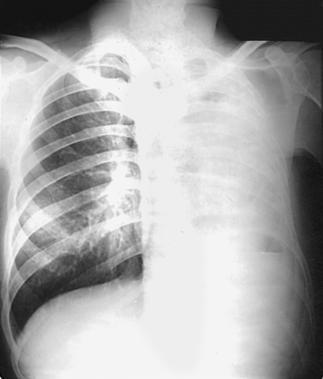
Fig. 10-19 Nongrid radiograph showing fluid-type pathologic condition in same patient as in Fig. 10-20.
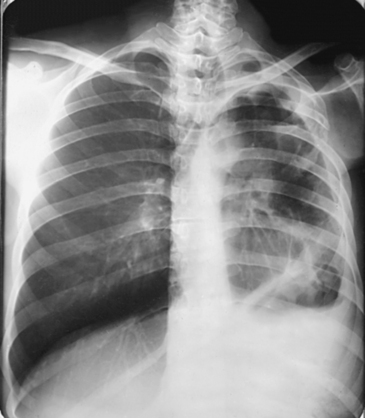
Fig. 10-20 Grid radiograph of the same patient as in Fig. 10-19.
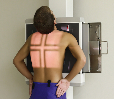
Radiation Protection
Protection of the patient from unnecessary radiation is the professional responsibility of the radiographer (see Chapter 1 for specific guidelines). In this chapter, the Shield gonads statement indicates that the patient is to be protected from unnecessary radiation by restricting the radiation beam using proper collimation. In addition, the placement of lead shielding between the gonads and the radiation source is appropriate when the clinical objectives of the examination are not compromised. An example of a properly placed lead shield is shown in Fig. 10-25.
AP PROJECTION
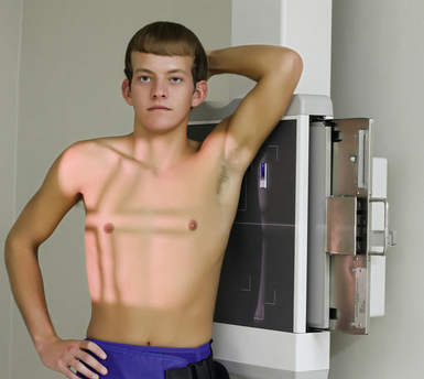
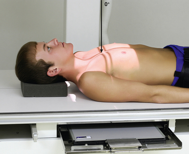
When preparing to radiograph the trachea for the AP projection, use a grid technique to minimize scatter radiation because the kVp must be high enough to penetrate the sternum and the cervical vertebrae.
• Center the midsagittal plane of the body to the midline of the grid.
• Adjust the patient’s shoulders to lie in the same transverse plane.
• Extend the patient’s neck slightly, and adjust it so that the midsagittal plane is perpendicular to the plane of the IR (Fig. 10-21).
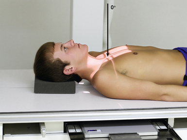
Fig. 10-21 AP trachea. (The new positioning photographs in this chapter were submitted by Scott Slinkard, a radiography student at the Southeast Hospital College of Nursing & Health Sciences in Cape Girardeau, Missouri. The model in the photos is Tyler Glueck, also a student in the same program. The authors thank these students for their contribution to Merrill’s.)
• Center the IR at the level of the manubrium.
• Collimate closely to the neck.
• Respiration: Instruct the patient to inhale slowly during the exposure to ensure that the trachea is filled with air.
Structures shown: AP projection shows the outline of the air-filled trachea. Under normal conditions, the trachea is superimposed on the shadow of the cervical vertebrae (Fig. 10-22).
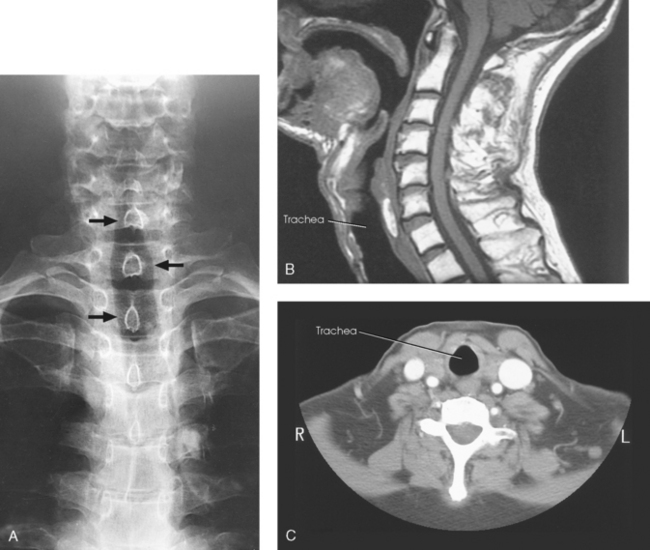
Fig. 10-22 A, AP trachea during inspiration showing air-filled trachea (arrows). CT and MRI are often used to evaluate the trachea and surrounding tissues. B, Sagittal MRI of neck. C, Axial CT of neck. (B and C, Modified from Kelley LL, Petersen CM: Sectional anatomy for imaging professionals, ed 2, St Louis, 2007, Mosby.)
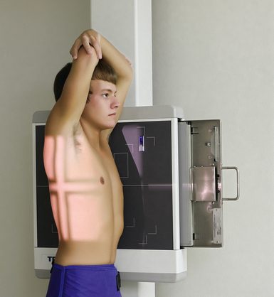
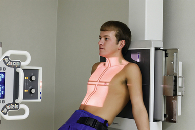
Trachea and Superior Mediastinum
R or L position
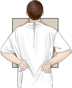
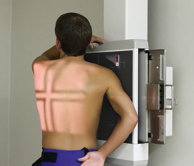
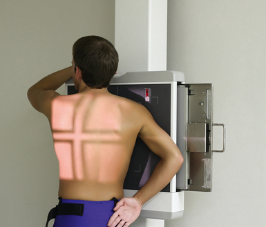
• Instruct the patient to clasp the hands behind the body and rotate the shoulders posteriorly as far as possible (Fig. 10-23). This position keeps the superimposed shadows of the arms from obscuring the structures of the superior mediastinum. If necessary, immobilize the arms in this position with a wide bandage.
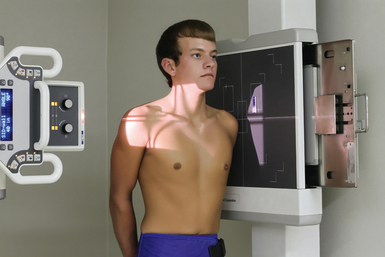
• Adjust the patient’s position to center the trachea to the midline of the IR. The trachea lies in the coronal plane that passes approximately midway between the jugular notch and the midcoronal plane.
• Adjust the height of the IR so that the upper border is at or above the level of the laryngeal prominence.
• Readjust the position of the body, being careful to have the midsagittal plane vertical and parallel with the plane of the IR.
• Respiration: Make the exposure during slow inspiration to ensure that the trachea is filled with air.
• Horizontal through a point midway between the jugular notch and the midcoronal plane (Fig. 10-24, A) and through a point 4 to 5 inches (10.2 to 12.7 cm) lower to show the superior mediastinum (Fig. 10-24, B)
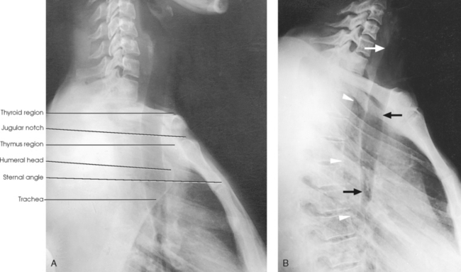
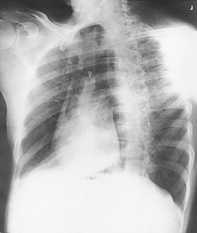
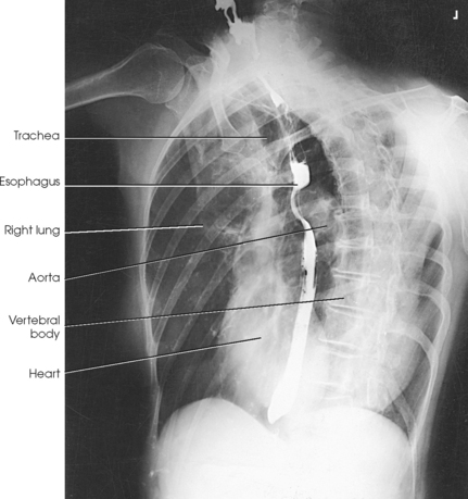
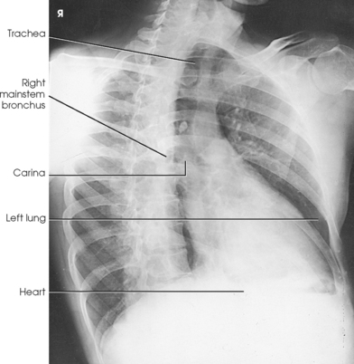
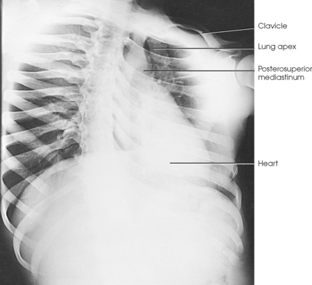
Structures shown: A lateral projection shows the air-filled trachea and the regions of the thyroid and thymus glands. This projection, first described by Eiselberg and Sgalitzer,1 is used extensively to show retrosternal extensions of the thyroid gland, thymic enlargement in infants (in the recumbent position), and the opacified pharynx and upper esophagus and an outline of the trachea and bronchi. It is also used to locate foreign bodies.
Lungs and Heart
SID: Minimum SID of 72 inches (183 cm) is recommended to decrease magnification of the heart and increase recorded detail of the thoracic structures.
• Place the patient, with arms hanging at sides, before a vertical grid device.
• Adjust the height of the IR so that its upper border is about 1½ to 2 inches (3.8 to 5 cm) above the relaxed shoulders.
• Center the midsagittal plane of the patient’s body to the midline of the IR.
• Have the patient stand straight, with the weight of the body equally distributed on the feet.
• Extend the patient’s chin upward or over the top of the grid device, and adjust the head so that the midsagittal plane is vertical.
• Ask the patient to flex the elbows and to rest the backs of the hands low on the hips, below the level of the costophrenic angles. Depress the shoulders and adjust to lie in the same transverse plane. These movements will position the clavicles below the apices of the lungs.
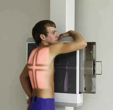
• Rotate the shoulders forward so that both touch the vertical grid device. This movement will rotate the scapula outward and laterally to remove them from the lungs (Figs. 10-25 and 10-26).
• If an immobilization band is used, be careful not to rotate the body when applying the band. The least amount of rotation results in considerable distortion of the heart shadow.
• If a female patient’s breasts are large enough to be superimposed over the lower part of the lung fields, especially the costophrenic angles, ask the patient to pull the breasts upward and laterally. This is especially important when ruling out the presence of fluid. Have the patient hold the breasts in place by leaning against the IR holder (Figs. 10-27 and 10-28).
• Shield gonads: Place a lead shield between the x-ray tube and the patient’s pelvis (see Fig. 10-25).
 Respiration: Full inspiration. The exposure is made after the second full inspiration to ensure maximum expansion of the lungs. The lungs expand transversely, anteroposteriorly, and vertically, with vertical being the greatest dimension.
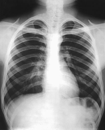
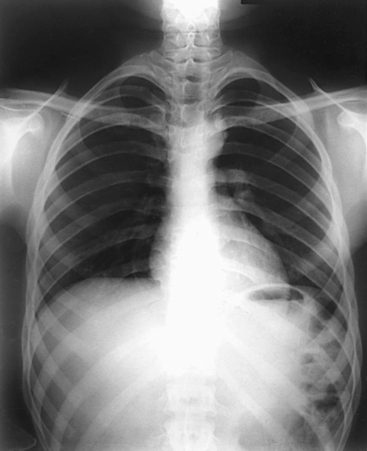
For certain conditions, such as pneumothorax and the presence of a foreign body, radiographs are sometimes made at the end of full inspiration and expiration (Figs. 10-29 to 10-31). Pneumothorax is shown more clearly on expiration because collapse of the lung is accentuated.
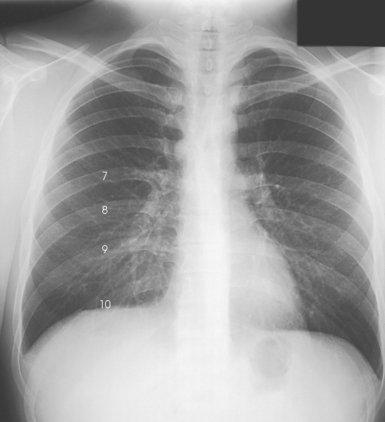
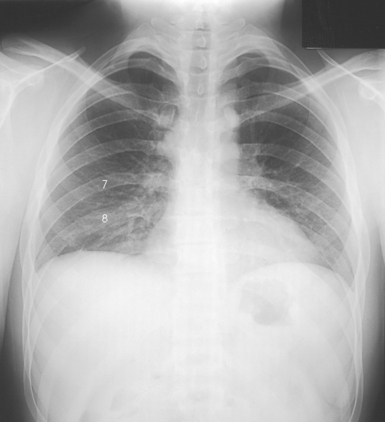
Fig. 10-30 Expiration in the same patient as in Fig. 10-29 (posterior rib numbers).
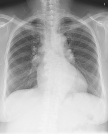
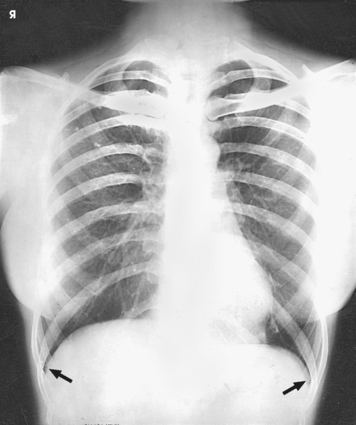
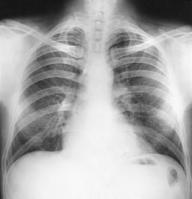
Structures shown: PA projection of the thoracic viscera shows the air-filled trachea, the lungs, the diaphragmatic domes, the heart and aortic knob, and, if enlarged laterally, the thyroid or thymus gland (Fig. 10-32). The vascular markings are much more prominent on the projection made at the end of expiration. The bronchial tree is shown from an oblique angle. The esophagus is well shown when it is filled with a barium sulfate suspension.
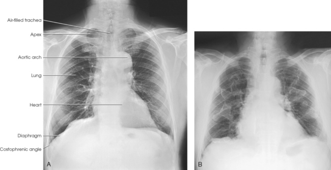
Fig. 10-32 A, PA chest in a man. B, PA chest showing pneumoconiosis in both lungs (multiple, irregular-shaped white areas are built-up coal dust).
The following should be clearly shown:
Evidence of proper collimation
Entire lung fields from the apices to the costophrenic angles
No rotation; sternal ends of the clavicles equidistant from the vertebral column
Trachea visible in the midline
Scapulae projected outside the lung fields
Ten posterior ribs visible above the diaphragm
Sharp outlines of heart and diaphragm
Faint shadow of the ribs and superior thoracic vertebrae visible through the heart shadow
Lung markings visible from the hilum to the periphery of the lung
With inspiration and expiration chest images, diaphragm shown on expiration at a higher level so that at least one less rib is seen within the lung field
NOTE: Inferior lobes of both lungs should be carefully checked for adequate penetration on women with large, pendulous breasts.
Cardiac studies with barium: PA chest radiographs are often obtained with the patient swallowing a bolus of barium sulfate to outline the posterior heart and aorta. The barium used in cardiac examinations should be thicker than the barium used for the stomach so that the contrast medium descends more slowly and adheres to the esophageal walls. The patient should hold the barium in the mouth until just before the exposure is made. Then the patient takes a deep breath and swallows the bolus of barium; the exposure is made at this time (see Fig. 10-7).
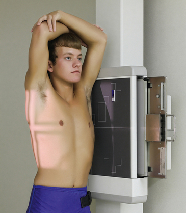
Lungs and Heart
R or L position
SID: Minimum SID of 72 inches (183 cm) is recommended to decrease magnification of the heart and increase recorded detail of the thoracic structures.
• If possible, always examine the patient in the upright position, either standing or seated, so that the diaphragm is at its lowest position, and air and fluid levels can be seen. Engorgement of the pulmonary vessels is also avoided.
• Turn the patient to a true lateral position, with arms by the sides.
• To show the heart and left lung, use the left lateral position with the patient’s left side against the IR.
• Use the right lateral position to show the right lung best.
• Adjust the position of the patient so that the midsagittal plane of the body is parallel with the IR and the adjacent shoulder is touching the grid device.
• Center the thorax to the grid; the midcoronal plane should be perpendicular and centered to the midline of the grid.
• Have the patient extend the arms directly upward, flex the elbows, and with the forearms resting on the elbows, hold the arms in position (Figs. 10-33 and 10-34).
• Place an intravenous catheter stand in front of an unsteady patient. Have the patient extend the arms and grasp the stand as high as possible for support.
• Adjust the height of the IR so that the upper border is about 1½ to 2 inches (3.8 to 5 cm) above the shoulders.
• Recheck the position of the body; the midsagittal plane must be vertical. Depending on the width of the shoulders, the lower part of the thorax and hips may be a greater distance from the IR, but this body position is necessary for a true lateral projection. Having the patient lean against the grid device (foreshortening) results in distortion of all thoracic structures (Fig. 10-35). Forward bending also results in distorted structural outlines (Fig. 10-36).
• Respiration: Full inspiration. The exposure is made after the second full inspiration to ensure maximum expansion of the lungs.
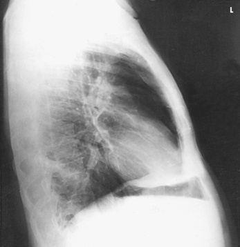
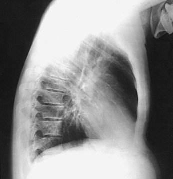
Structures shown: The preliminary left lateral chest position is used to show the heart, the aorta, and left-sided pulmonary lesions (Figs. 10-37 and 10-38). The right lateral chest position is used to show right-sided pulmonary lesions (Fig. 10-39). These lateral projections are employed extensively to show the interlobar fissures, to differentiate the lobes, and to localize pulmonary lesions.
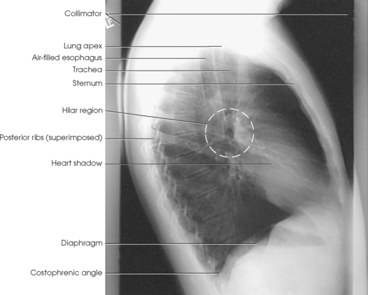
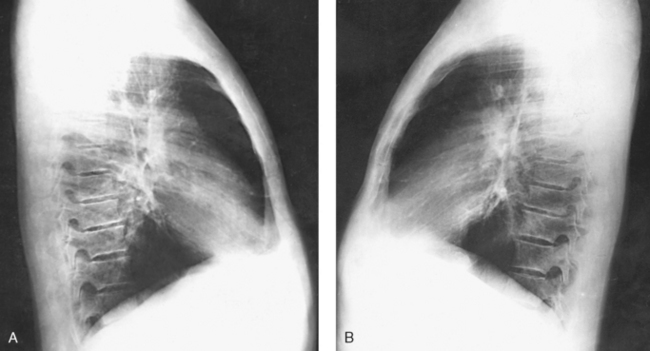
Fig. 10-38 A, Left lateral chest. B, Right lateral chest on same patient as in A. Note the size of the heart shadows.
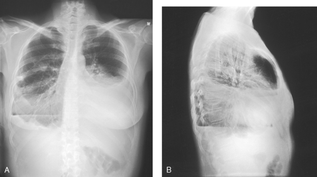
Fig. 10-39 A, PA chest. B, Lateral chest on same patient as in A. The importance of two projections is seen on this patient with multiple chest pathologies, including fluid, air-fluid level, pneumothorax, and enlarged heart.
The following should be clearly shown:
Evidence of proper collimation
Superimposition of the ribs posterior to the vertebral column
Arm or its soft tissues not overlapping the superior lung field
Long axis of the lung fields shown in vertical position, without forward or backward leaning
Lateral sternum with no rotation
Costophrenic angles and the lower apices of the lungs
Penetration of the lung fields and heart
Open thoracic intervertebral spaces and intervertebral foramina except in patients with scoliosis
Cardiac studies with barium: The left lateral position is traditionally used during cardiac studies with barium. The procedure is the same as described for the PA chest projection (see p. 508).
Lungs and Heart
RAO and LAO positions
SID: Minimum SID of 72 inches (183 cm) is recommended to decrease magnification of the heart and to increase recorded detail of the thoracic structures.
• Maintain the patient in the position (standing or seated upright) used for the PA projection.
• Instruct the patient to let the arms hang free.
• Have the patient turn approximately 45 degrees toward the left side for LAO position and approximately 45 degrees toward the right side for RAO position.
• Ask the patient to stand or sit straight. If the standing position is used, the weight of the patient’s body must be equally distributed on the feet to prevent unwanted rotation.
• For PA oblique projections, the side of interest is generally the side farther from the IR; however, the lung closest to the IR is also imaged.
• The top of the IR should be placed about 1½ to 2 inches (3.8 to 5 cm) above the vertebral prominens because the top of the shoulders may not be on the same plane.
• Rotate the patient 45 degrees to place the left shoulder in contact with the grid device, and center the thorax to the IR. Ensure that the right and left sides of the body are positioned to the IR.
• Instruct the patient to place the left hand on the hip with the palm outward.
• Have the patient raise the right arm to shoulder level and grasp the top of the vertical grid device for support.
• Adjust the patient’s shoulders to lie in the same horizontal plane, and instruct the patient not to rotate the head (Fig. 10-40).
• Use a 55- to 60-degree oblique position when the examination is performed for a cardiac series. This projection is usually performed with barium contrast medium. The patient swallows the barium just before the exposure.
• Respiration: Full inspiration. The exposure is made after the second full inspiration to ensure maximum expansion of the lungs.
• Reverse the previously described position, placing the patient’s right shoulder in contact with the grid device, the right hand on the hip, and the left hand on the top of the vertical grid device (Figs. 10-41 and 10-42).
• Respiration: Full inspiration. The exposure is made after the second full inspiration to ensure maximum expansion of the lungs.
LAO position: The maximum area of the right lung field (side farther from the IR) is shown along with the thoracic viscera. The anterior portion of the left lung is superimposed by the spine (Figs. 10-43 and 10-44). Also shown are the trachea and its bifurcation (the carina) and the entire right branch of the bronchial tree. The heart, the descending aorta (lying just in front of the spinae), and the arch of the aorta are also presented.
RAO position: The maximum area of the left lung field (side farther from the IR) is shown along with the thoracic viscera. The anterior portion of the right lung is superimposed by the spine (Figs. 10-45 and 10-46). Also shown are the trachea and the entire left branch of the bronchial tree. This position gives the best image of the left atrium, the anterior portion of the apex of the left ventricle, and the right retrocardiac space. When filled with barium, the esophagus is shown clearly in the RAO and LAO positions (see Fig. 10-46).
NOTE: The radiographs in this section, similar to the radiographs throughout this text, are printed as though the reader is looking at the patient’s anterior body surface (see Chapter 1).
Barium studies: RAO and LAO positions are routinely used during cardiac studies with barium. Follow the same procedure described in the PA chest section (see p. 507).
NOTE: A slight oblique position has been found to be of particular value in the study of pulmonary diseases. The patient is turned only slightly (10 to 20 degrees) from the RAO or LAO body position. This slight degree of obliquity rotates the superior segment of the respective lower lobe from behind the hilum and displays the medial part of the right middle lobe or the lingula of the left upper lobe free from the hilum. These areas are not clearly shown in the standard “cardiac oblique” of 45- to 60-degree rotation, largely because of superimposition of the spine.
Lungs and Heart
RPO and LPO positions
RPO and LPO positions are used when the patient is too ill to be turned to the prone position and sometimes as supplementary positions in the investigation of specific lesions. These positions are also used with the recumbent patient in contrast studies of the heart and great vessels.
One point the radiographer must bear in mind is that RPO corresponds to the LAO position and LPO corresponds to the RAO position. For AP oblique projections, the side of interest is generally the side closest to the IR. The resulting image shows the greatest area of the lung closest to the IR. The lung farthest from the IR is also imaged, and diagnostic information is often obtained for that side.
SID: Minimum SID of 72 inches (183 cm) is recommended to decrease magnification of the heart and increase recorded detail of the thoracic structures.
• Rotate the patient toward the correct side, adjust the body at a 45-degree angle, and center the thorax to the grid.
• If the patient is recumbent, support the elevated hip and arm. Ensure that both sides of the chest are positioned to the IR.
• Flex the patient’s elbows and place the hands on the hips with the palms facing outward, or pronate the hands beside the hips. The arm closer to the IR may be raised as long as the shoulder is rotated anteriorly.
• Adjust the shoulders to lie in the same transverse plane in a position of forward rotation (Figs. 10-47 and 10-48).
• Respiration: Full inspiration. The exposure is made after the second full inspiration to ensure maximum expansion of the lungs.
Structures shown: This radiograph presents an AP oblique projection of the thoracic viscera similar to the corresponding PA oblique projection (Fig. 10-49). The RPO position is comparable to the LAO position. The lung field of the elevated side usually appears shorter, however, because of magnification of the diaphragm. The heart and great vessels also cast magnified shadows as a result of being farther from the IR.
 AP PROJECTION*
The supine position is used when the patient is too ill to be turned to the prone position. It is sometimes used as a supplementary projection in the investigation of certain pulmonary lesions.
SID: SID of 72 inches (183 cm) or 60 inches (150 cm) is recommended if it can be attained using the equipment available.
• Center the midsagittal plane of the chest to the IR.
• Adjust the IR so that the upper border is approximately 1½ to 2 inches (3.8 to 5 cm) above the relaxed shoulders.
• If possible, flex the patient’s elbows, pronate the hands, and place the hands on the hips to draw the scapulae laterally. (This maneuver is often impossible, however, because of the condition of the patient.)
• Adjust the shoulders to lie in the same transverse plane (Fig. 10-50).
• Respiration: Full inspiration. The exposure is made after the second full inspiration to ensure maximum expansion of the lungs.
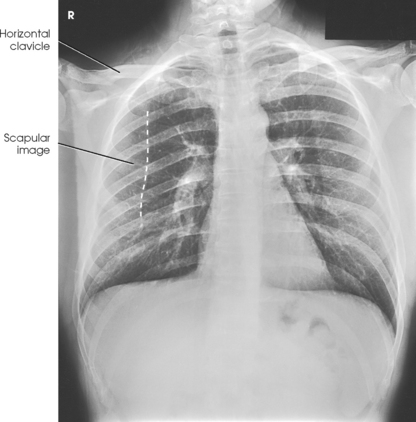
Structures shown: An AP projection of the thoracic viscera (Fig. 10-51) shows an image similar to the PA projection (Fig. 10-52). Being farther from the IR, the heart and great vessels are magnified and engorged, and the lung fields appear shorter because abdominal compression moves the diaphragm to a higher level. The clavicles are projected higher, and the ribs assume a more horizontal appearance.
The following should be clearly shown:
Evidence of proper collimation
Medial portion of the clavicles equidistant from the vertebral column
Trachea visible in the midline
Clavicles lying more horizontal and obscuring more of the apices than in the PA projection
Equal distance from the vertebral column to the lateral border of the ribs on each side
Faint image of the ribs and thoracic vertebrae visible through the heart shadow
Entire lung fields, from the apices to the costophrenic angles
Pleural vascular markings visible from the hilar regions to the periphery of the lungs
NOTE: Resnick1 recommended an angled AP projection to free the basal portions of the lung fields from superimposition by the anterior diaphragmatic, abdominal, and cardiac structures. He reported that this projection also differentiates middle lobe and lingular processes from lower lobe disease. For this projection, the patient may be either upright or supine, and the central ray is directed to the mid-sternal region at an angle of 30 degrees caudad. Resnick stated that a more suitable angulation may be chosen based on the preliminary films.
1Resnick D: The angulated basal view: a new method for evaluation of lower lobe pulmonary disease, Radiology 96:204, 1970.
Pulmonary Apices
Lordotic position
SID: Minimum SID of 72 inches (183 cm) is recommended to decrease magnification of the heart and to increase recorded detail of the thoracic structures.
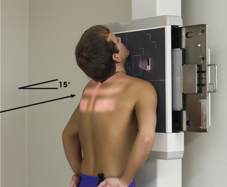
• Adjust the height of the IR so that the upper margin is about 3 inches (7.6 cm) above the upper border of the shoulders when the patient is adjusted in the lordotic position.
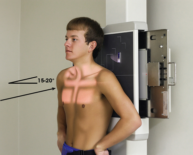
• Adjust the patient for the AP axial projection, with the coronal plane of the thorax 15 to 20 degrees from vertical and the midsagittal plane centered to the midline of the grid (Fig. 10-53).
Oblique lordotic positions—LPO or RPO:
• Rotate the patient’s body approximately 30 degrees away from the position used for the AP projection, with the affected side toward and centered to the grid (Fig. 10-54).
• With either of the preceding positions, have the patient flex the elbows and place the hands, palms out, on the hips.
• Have the patient lean backward in a position of extreme lordosis and rest the shoulders against the vertical grid device.
• Respiration: Full inspiration. The exposure is made after the second full inspiration to ensure maximum expansion of the lungs.
Structures shown: AP axial (Fig. 10-55) and AP axial oblique (Fig. 10-56) images of the lungs show the apices and conditions such as interlobar effusions.
The following should be clearly shown:
Clavicles lying superior to the apices
Sternal ends of the clavicles equidistant from the vertebral column
Apices and lungs in their entirety
Clavicles lying horizontally with their medial ends overlapping only the first or second ribs
Ribs distorted with their anterior and posterior portions superimposed
PA AXIAL PROJECTION
SID: Minimum SID of 72 inches (183 cm) is recommended to decrease magnification of the heart and to increase recorded detail of the thoracic structures.
• Adjust the height of the IR so that it is centered at the level of the jugular notch.
• Center the midsagittal plane of the patient’s body to the midline of the IR, and rest the chin against the grid device.
• Adjust the patient’s head so that the midsagittal plane is vertical, and then flex the elbows and place the hands, palms out, on the hips.
• Depress the patient’s shoulders, rotate them forward, and adjust them to lie in the same transverse plane.
• Instruct the patient to keep the shoulders in contact with the grid device to move the scapulae from the lung fields (Fig. 10-57).
• Respiration: Make the exposure at the end of full inspiration or as an option, at full expiration. The clavicles are elevated by inspiration and depressed by expiration; the apices move little, if at all, during either phase of respiration.
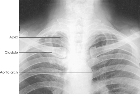
Structures shown: The apices are projected above the shadows of the clavicles in the PA axial and PA projections (Fig. 10-58).
AP AXIAL PROJECTION
NOTE: This projection is recommended when the patient cannot be positioned for the lordotic position.
SID: Minimum SID of 72 inches (183 cm) is recommended to decrease magnification of the heart and to increase recorded detail of the thoracic structures.
• Center the IR to the midsagittal plane at the level of T2, and adjust the patient’s body so that it is not rotated.
• Flex the patient’s elbows and place the hands on the hips with the palms out, or pronate the hands beside the hips.
• Place the shoulders back against the grid and adjust them to lie in the same transverse plane (Fig. 10-59).
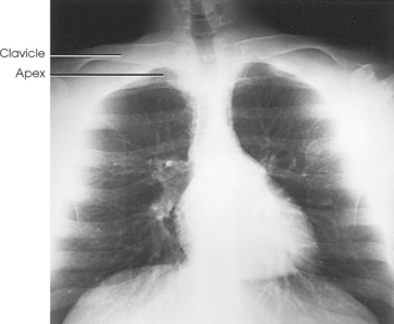
Structures shown: AP axial projection shows the apices lying below the clavicles (Fig. 10-60).
The following should be clearly shown:
Clavicles lying superior to the apices
Sternal ends of the clavicles equidistant from the vertebral column
Superior lung region adjacent to the apices
Clavicles lying horizontally with their medial ends overlapping only the first or second ribs
Ribs distorted, with their anterior and posterior portions superimposed
NOTE: The AP axial projection is used in preference to the PA axial projection in hypersthenic patients and patients whose clavicles occupy a high position. The AP axial projection makes it possible to separate the apical and clavicular shadows without undue distortion of the apices.
Lungs and Pleurae
AP OR PA PROJECTION*
R or L lateral decubitus positions
• Place the patient in a lateral decubitus position, lying on either the affected or the unaffected side, as indicated by the existing condition. A small amount of fluid in the pleural cavity is usually best shown with the patient lying on the affected side. With this positioning, the mediastinal shadows and the fluid do not overlap. A small amount of free air in the pleural cavity is generally best shown with the patient lying on the unaffected side.
• Exercise care to ensure that the patient does not fall off the cart. If a cart is used, lock all wheels securely in position.
• Achieve the best visualization by allowing the patient to remain in the position for 5 minutes before the exposure. This allows fluid to settle and air to rise.
• If the patient is lying on the affected side, elevate the body 5 to 8 cm (2 to 3 inches) on a suitable platform or a firm pad.
• Extend the arms well above the head, and adjust the thorax in a true lateral position (Fig. 10-61).
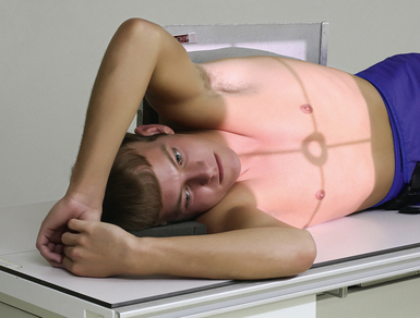
Fig. 10-61 AP projection, right lateral decubitus position. Side up is the affected side, so no table pad was used. This projection would demonstrate free air rising up to the left side.
• Place the anterior or posterior surface of the chest against a vertical grid device.
• Adjust the IR so that it extends approximately 1½ to 2 inches (3.8 to 5 cm) beyond the shoulders.
• Respiration: Full inspiration. The exposure is made after the second full inspiration to ensure maximum expansion of the lungs.
Structures shown: AP or PA projection obtained using the lateral decubitus position shows the change in fluid position and reveals any previously obscured pulmonary areas or, in the case of suspected pneumothorax, the presence of any free air (Figs. 10-62 to 10-64).
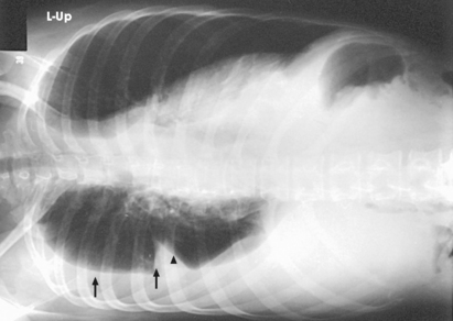
Fig. 10-62 AP projection, right lateral decubitus position, showing a fluid level (arrows) on the side that is down. Note the fluid in the lung fissure (arrowhead). Note correct marker placement, with the upper side of the patient indicated.
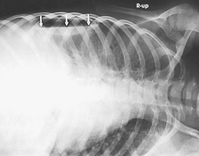
Fig. 10-63 AP projection, left lateral decubitus position, in same patient as in Fig. 10-64. Arrows indicate air-fluid level (air on the side up). Note correct marker placement, with upper side of the patient indicated.
The following should be clearly shown:
Evidence of proper collimation
No rotation of the patient from a true frontal position, as evidenced by the clavicles being equidistant from the spine
Proper identification visible to indicate that decubitus was performed
NOTE: An exposure made with the patient leaning directly laterally from the upright PA position is sometimes useful for showing fluid levels in pulmonary cavities. Ekimsky* recommended this position, with the patient leaning laterally 45 degrees, to show small pleural effusions. He reported that the inclined position is simpler to perform than the decubitus position and is equally satisfactory.
*Ekimsky B: Comparative study of lateral decubitus views and those with lateral body inclination in small pleural effusions, Vestn Rentgenol Radiol 41:43, 1966. (In Russian.) Abstract: Radiology 87:1135, 1966.
LATERAL PROJECTION
R or L position Ventral or dorsal decubitus position
• With the patient in a prone or supine position, elevate the thorax 2 to 3 inches (5 to 7.6 cm) on folded sheets or a firm pad, centering the thorax to the grid.
• Achieve the best visualization by allowing the patient to remain in the position for 5 minutes before the exposure. This allows fluid to settle and air to rise.
• Adjust the body in a true prone or supine position, and extend the arms well above the head.
• Place the affected side against a vertical grid device, and adjust it so that the top of the IR extends to the level of the thyroid cartilage (Fig. 10-65).
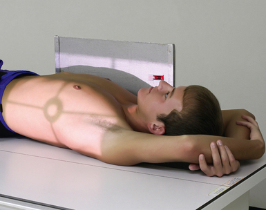
Fig. 10-65 Right lateral projection, dorsal decubitus position. Side up is the affected side, so no table pad was used. This projection would demonstrate free air rising up to the anterior chest.
• Respiration: Full inspiration. The exposure is made after the second full inspiration to ensure maximum expansion of the lungs.
Structures shown: A lateral projection in the decubitus position shows a change in the position of fluid and reveals pulmonary areas that are obscured by the fluid in standard projections (Figs. 10-66 and 10-67).
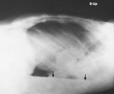
Fig. 10-66 Right lateral projection, dorsal decubitus position. Arrows indicate air-fluid level. Note correct marker placement, with upper side of the patient indicated.
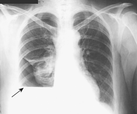
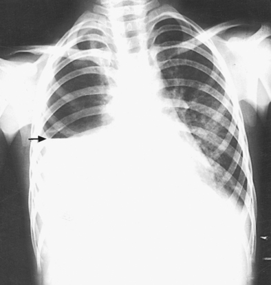
Fig. 10-67 Upright PA chest in same patient as in Fig. 10-66. Note right lung fluid level (arrow).