WRIST: ULNAR DEVIATION, POSTEROANTERIOR AXIAL PROJECTION (SCAPHOID)
See Figure 4-43 and Box 4-14.
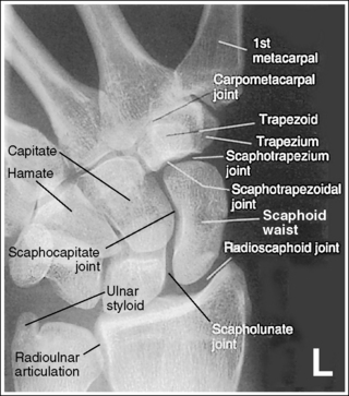
Contrast and density are adequate to demonstrate the scaphoid fat stripe.
• The scaphoid fat stripe is one of the soft tissue structures that should be visible on all scaphoid images (see Figure 4-30). It is convex and located just lateral to the scaphoid in an uninjured wrist.
The scaphotrapezium and scaphotrapezoidal joint spaces are open.
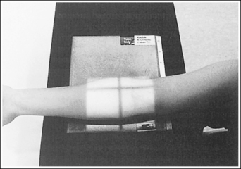
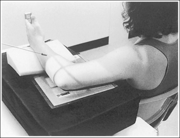
• To obtain an accurate PA axial (scaphoid) projection, abduct the humerus until it is positioned parallel with the IR and place the elbow in a flexed, lateral position. Then pronate the extended hand, place the wrist in ulnar deviation, and ensure the wrist is rotated medially approximately 25 degrees (Figure 4-44).

Figure 4-44 Proper patient positioning for ulnar-deviated, PA axial (scaphoid) wrist projection. X indicates location of the scaphoid.
• The scaphotrapezium and scaphotrapezoidal joints are aligned at a 15-degree angle to the IR when the patient's hand is in full extension. These joints will be open when a 15-degree proximally angled central ray is used. If the hand is not extended so that the palm is placed flat against the IR, but rather is flexed, the second metacarpal is superimposed over the trapezoid and trapezium and closes the scaphotrapezium and scaphotrapezoidal joint spaces (see Image 55).
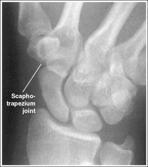
Image 55
The wrist is in maximum ulnar deviation, as demonstrated by the alignment of the long axis of the first metacarpal and the radius, and the position of the lunate distal to the radius. The scaphoid is demonstrated without foreshortening or excessive elongation. When a scaphoid fracture is indicated, the fracture line is demonstrated.
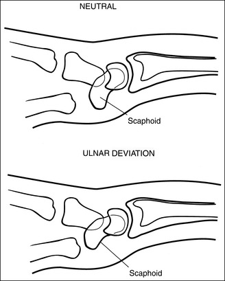
• To demonstrate the scaphoid without foreshortening, position the patient's wrist in maximum ulnar deviation; then direct a 15-degree proximal (toward the elbow) central ray angulation to the long axis of the scaphoid. Maximum ulnar deviation has been accomplished when the first metacarpal is aligned with the radius. In a neutral PA projection of the nondeviated wrist, the distal scaphoid tilts anteriorly approximately 20 degrees. This tilt results in foreshortening of the scaphoid on the PA axial projection (Figures 4-29 and 4-45). To offset some of this foreshortening and demonstrate more of the scaphoid, place the wrist in ulnar deviation. In ulnar deviation the distal scaphoid moves posteriorly, decreasing the degree of foreshortening by 5 degrees (see Figure 4-45).
Adequate ulnar deviation and central ray angulation place the central ray perpendicular to the long axis of the scaphoid (Figure 4-46). Because 70% of the fractures occur at the waist, most scaphoid fractures should be visualized with this positioning and angulation (see Image 56).

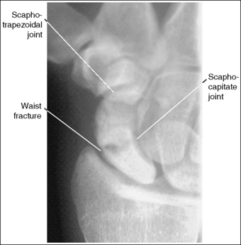
Image 56
• Compensating for inadequate ulnar deviation. Many patients with suspected scaphoid fractures are unable to achieve maximum ulnar wrist deviation. Without adequate ulnar deviation, the distal scaphoid is titled more anteriorly. To compensate for this increased anterior tilt, the central ray angulation should be increased to approximately 20 degrees to place the central ray and scaphoid long axis perpendicular to each other.
• Scaphoid elongation. The goal of the PA axial (scaphoid) projection is to demonstrate the scaphoid with the least amount of foreshortening or elongation. A slight amount of elongation of the scaphoid occurs on PA axial projections because the IR is not positioned parallel with the long axis of the scaphoid and the central ray is not aligned perpendicularly with the IR (Figure 4-46). Excessive elongation of the scaphoid results when the central ray is angled more than needed to align it perpendicularly to the long axis of the scaphoid.
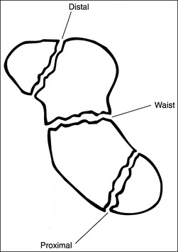
• Mechanics of scaphoid fracture. The scaphoid is the most commonly fractured carpal bone. One reason for this is its location among the other carpal bones. Two rows of carpal bones exist, a distal row and a proximal row, with joint spaces between them that allow the wrist to flex. The long scaphoid bone, however, is aligned partially with both these rows, with no joint space. When an individual falls on an outstretched hand, the wrist is hyperextended, causing the proximal and distal carpal rows to flex at the joints, and a great deal of stress is placed on the narrow waist of the scaphoid. This stress may result in a fracture.
• Three areas of the scaphoid may be fractured: the waist, which sustains approximately 70% of the fractures; the distal end, which sustains 20% of the fractures; and the proximal end, which sustains 10% (Figure 4-47). Because scaphoid fractures can be at different locations on the scaphoid, precise positioning and central ray angulation are essential to obtain the optimum demonstration of this bone.
• Demonstrating fractures of distal and proximal scaphoid. When a fracture is suspected because of persistent pain and obliteration of the fat stripe but has not been demonstrated on routine images, it may be necessary to use different angles to position the central ray parallel with these fractures sites (Figure 4-48). A decrease of 5 to 10 degrees in central ray angulation better demonstrates the proximal scaphoid. Compare Figures 4-49 and 4-50. These PA axial projections demonstrate a proximal fracture. Figure 4-49 was taken with the typical 15-degree proximal angle, and Figure 4-50 was taken with a 5-degree proximal angle. Note the increase in fracture line visualization in Figure 4-50. Increase the central ray angle by 5 to 10 degrees, with a maximum of 25 degrees, to demonstrate a distal scaphoid fracture best (Figure 4-51). Angulations more than 25 degrees project the proximal second metacarpal onto the distal scaphoid, obscuring the area of interest (see Image 57).
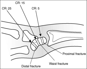

Figure 4-49 PA axial (scaphoid) projection taken with a 15-degree proximal central ray angle demonstrating a proximal scaphoid fracture.
Figure 4-50 PA axial (scaphoid) projection taken with a 5-degree proximal central ray angle demonstrating a proximal scaphoid fracture.


Image 57
The scaphocapitate and scapholunate joints are open. The ulnar styloid is in profile medially.
• The scaphocapitate and scapholunate joints are open when the wrist is medially rotated approximately 25 degrees. This obliquity is accomplished somewhat naturally as the patient's wrist is ulnar-deviated, with the humerus abducted and positioned parallel with the IR, and the elbow placed in a flexed lateral projection. If the scaphocapitate joint space is closed and the capitate and hamate are demonstrated without superimposition, the degree of obliquity was insufficient (see Image 58). If the scapholunate joint space is closed and the capitate and hamate demonstrate some degree of superimposition, the wrist was rotated more than needed (see Image 59). Excessive external wrist obliquity often occurs when the humerus and forearm are not positioned on the same horizontal plane and the elbow is not placed in a lateral projection. On a PA axial projection, one can judge accurate humerus, forearm, and elbow positioning by evaluating the ulnar styloid. Accurate positioning places the ulnar styloid in profile medially. If the arm is not positioned accurately, the ulnar styloid is demonstrated distal to the midline of the ulnar head (see Image 60).

Image 58
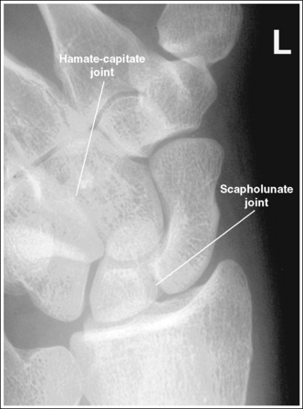
Image 59

Image 60
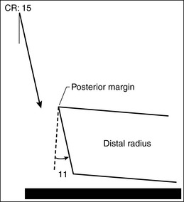
The radioscaphoid joint space is open.
• The distal radial carpal articular surface is concave and slants approximately 11 degrees from posterior to anterior when the forearm is positioned parallel with the IR. On a PA projection without a central ray angulation, the posterior radial margin is demonstrated slightly distal to the anterior margin if the forearm is placed parallel with the IR. When a 15-degree proximal central ray angulation is used for the PA axial (scaphoid) projection, the posterior margin is projected slightly proximal to the anterior margin (Figure 4-52). To demonstrate an open radioscaphoid joint, the anterior and posterior margins of the distal radius should be superimposed. This superimposition is accomplished by elevating the proximal forearm very slightly (2 degrees) above the distal forearm.
The scaphoid is at the center of the exposure field. The carpal bones, the radioulnar articulation, and the proximal first through fourth metacarpals are included within the collimated field.
• To place the scaphoid at the center of the collimated field, center the central ray with the scaphoid. In ulnar deviation, the scaphoid can be palpated halfway between the first metacarpal base and the radial styloid. After the central ray is centered, open the longitudinal collimation to include the first through fourth metacarpal bases and the distal radius. Transversely collimate to within 0.5 inch (1.25 cm) of the wrist skin line.
Avoid collimating too tightly. It is difficult to determine how to reposition the patient when an image reveals poor positioning if key anatomic structures are not included.
• Half of an 8- × 10-inch (18- × 24-cm) detailed screen-film or computed radiography IR placed crosswise should be adequate to include all the required anatomic structures.
Posteroanterior Axial (Scaphoid) Projection Analysis
The scaphotrapezium, scaphotrapezoidal, and CM joint spaces are closed. The hand and fingers were not positioned flat against the IR.
Analysis
This image demonstrates a scaphoid waist fracture. The scaphotrapezium, scaphotrapezoidal, and CM joint spaces are closed. The hand and fingers were not positioned flat against the IR. The scaphocapitate and radioscaphoid joints are closed, indicating that the degree of obliquity was inadequate and the proximal forearm was slightly depressed, respectively.
Correction
Extend the patient's fingers, placing the hand flat against the IR, and slightly increase the amount of external wrist obliquity and elevate the proximal forearm.
Analysis
A 30-degree proximal central ray angle was used, with the hand and fingers positioned flat against the IR. A distal scaphoid fracture is present. The proximal first metacarpal is superimposed over the distal scaphoid, and the radioscaphoid joint is closed. The central ray angulation was too great, and the proximal forearm was slightly depressed.
Correction
To demonstrate a distal scaphoid fracture best, decrease the amount of central ray angulation. A maximum 25-degree angle should be used to demonstrate a distal scaphoid fracture. Compare this image with one shown in Figure 4-51, which was taken on the same patient with a 25-degree angle. Slightly elevate the proximal forearm to open the radioscaphoid joint.
Analysis
The scaphocapitate joint is closed and the hamate-capitate joint is open. The wrist was not externally rotated enough.
Analysis
The scapholunate and hamate-capitate joints are closed. The wrist was externally rotated more than needed.
Analysis
The scapholunate and hamate-capitate joints are closed. The wrist was externally rotated more than needed. The styloid process is demonstrated distal to the ulnar head midline. The humerus was not abducted with the elbow in a flexed lateral projection. The scaphoid is not in the center of the field, and the proximal metacarpals are not included on the image.
WRIST CARPAL CANAL: TANGENTIAL, INFEROSUPERIOR PROJECTION
See Figure 4-53 and Box 4-15.
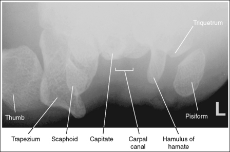
The pisiform is demonstrated without superimposition of the hamulus of the hamate, and the carpal canal is clearly demonstrated.
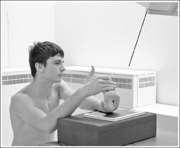
• The tangential, inferosuperior carpal canal wrist projection is accomplished by placing the distal forearm and wrist on the IR in a PA projection, and then hyperextending (dorsiflexing) the wrist until the long axis of the metacarpals are close to vertical while the wrist remains in contact with the IR. To obtain adequate wrist hyperextension, have the patient grasp his or her fingers with the opposite hand and gently pull them posteriorly (Figure 4-54).
• The tangential, inferosuperior carpal canal projection is used to evaluate the carpal canal for the narrowing that results in carpal canal syndrome and demonstrate fractures of the pisiform and hamulus of the hamate. The carpal canal is a passageway formed anteriorly by the flexor retinaculum, posteriorly by the capitate, laterally by the scaphoid and trapezium, and medially by the pisiform and hamate (Figure 4-55). Fractures of the pisiform and hamulus process are best demonstrated when they are seen without superimposition. This is accomplished by rotating the patient's hand 10 degrees internally (toward the radial side) until the fifth metacarpal is aligned perpendicularly to the IR. If the hand is not internally rotated, the pisiform will be superimposed over the hamulus process on the resulting image (see Image 61).

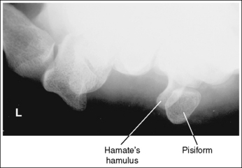
Image 61
The carpal canal is visualized in its entirety, and the carpal bones are demonstrated with only slight elongation.
• To show the carpal canal and demonstrate the carpals with only slight elongation, the patient's hand is positioned vertically, and the central ray is angled proximally (toward the palmar surface). The degree of central ray angulation that is needed will depend on how vertical the patient can bring the hand. To determine the angle to use, adjust the central ray proximally until it is aligned at a 15-degree angle with the palmar surface (Figure 4-56). The most common tube angle used is 25 to 30 degrees.
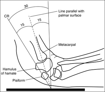
• Immaculate angle. If the angle between the central ray and palmar surface is too great, the carpal canal will not be fully demonstrated and the carpal bones will be foreshortened (see Image 62). If the angle between the central ray and palmar surface is too small, the bases of the hamulus process, pisiform, and scaphoid are obscured by the metacarpal bases (see Image 63).

Image 62

Image 63
• Insufficient wrist extension. When imaging a patient who is unable to extend the wrist enough to place the palmar surface even close to vertical, the resulting image will demonstrate adequate visualization of the carpal bones and carpal canal, although there will be increased elongation as the angle between the central ray and IR becomes more acute (see Image 64).
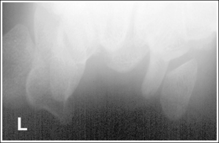
Image 64
The carpal canal is at the center of the exposure field. The trapezium, distal scaphoid, pisiform, and hamulus of the hamate are included within the collimated field.
• The carpal canal is positioned in the center of the collimated field by centering the central ray to center of the palm of the hand. After the central ray is centered, open the longitudinal and transverse collimations to within 0.5 inch (1.25 cm) of the wrist skin line.
• Half of an 8- × 10-inch (18- × 24-cm) detailed screen-film or computed IR placed crosswise should be adequate to include all the required anatomic structures.
Tangential, Inferosuperior Carpal Canal Wrist Projection Analysis
The pisiform is superimposed over the hamulus of the hamate. The patient's wrist and distal forearm were either in a PA projection or in slight external (toward the ulnar side) rotation.
Analysis
The carpal canal is not demonstrated in its entirety, and the carpal bones are foreshortened. The angle between the central ray and palmar surface was too great.
Correction
Decrease the central ray angle until it is at a 15-degree angle with the palmar surface (Figure 4-56).
Analysis
The metacarpal bases obscure the bases of the hamate's hamulus process, pisiform, and scaphoid. The angle between the central ray and palmar surface was too small.
Correction
Increase the central ray angle until it is at a 15-degree angle with the palmar surface (Figure 4-56), or increase the amount of wrist hyperextension by pulling the fingers posteriorly until the metacarpals are vertical.
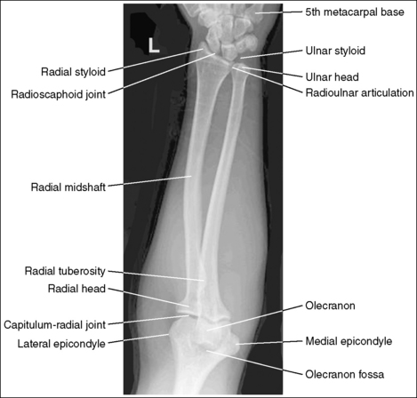
FOREARM: ANTEROPOSTERIOR PROJECTION
See Figure 4-57 and Box 4-16.
Image density is uniform across entire forearm.
• Anode heel effect. To use the anode heel effect to obtain uniform density across the forearm, position the thinner wrist (distal forearm) at the anode end of the tube and the thicker elbow (proximal forearm) at the cathode end. Set an exposure (mAs) that will adequately demonstrate the midpoint of the forearm.
The long axis of the forearm is aligned with the long axis of the collimated field.
• Aligning the long axis of the forearm with the long axis of the collimated field enables you to collimate tightly without clipping the distal or proximal forearm.
The forearm midpoint is at the center of the exposure field. The wrist and elbow joints and forearm soft tissue are included within the collimated field.
• A perpendicular central ray is centered to the midpoint of the forearm to place it in the center of the image.
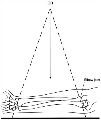
• When the wrist and elbow joints are included on the image, the degree of radiation beam divergence used to image a long body part needs to be considered (Figure 4-58).
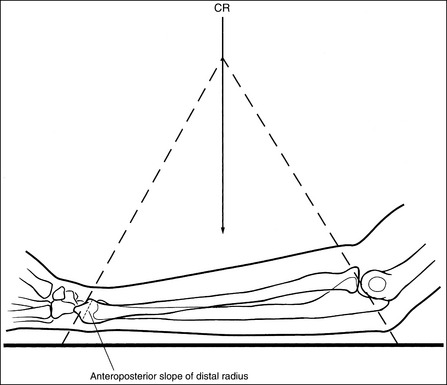
• IR length for the forearm. Choose an IR that is long enough to allow at least 1 inch (2.5 cm) of IR to extend beyond each joint space; half of a 14- × 17-inch (35- × 44-cm) IR placed lengthwise should be adequate. To ensure that the IR extends beyond the elbow joint, palpate the medial epicondyle, which is located approximately 0.75 inch (2 cm) proximal to the elbow joint. To ensure that the IR extends beyond the wrist joint, palpate the base of the first metacarpal; the wrist joint is located just proximal to this base. Digital imaging requires tight collimation without overlapping of individual exposures.
• Central ray centering and collimation. Once the forearm is accurately positioned in relation to the IR, center the central ray with the midpoint of the forearm and open the longitudinal collimation field until it extends just beyond the elbow and the wrist. If the collimation does not extend beyond the joints, adjust the centering point of the central ray until both the elbow and the wrist joint are included within the collimated field without demonstrating an excessive field beyond them. Transverse collimation should be within 0.5 inch (1.25 cm) of the forearm skin line.
Distal Forearm Positioning
The distal and proximal forearm is positioned in an AP projection. The radial styloid is demonstrated in profile laterally, and superimposition of the metacarpal bases and of the radius and ulna is minimal.
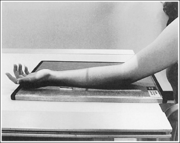
• To obtain an AP projection of the distal forearm, supinate the hand and place the second through fifth metacarpal heads against the IR (Figure 4-59).

• Detecting distal forearm rotation. Rotation of the distal forearm results from inaccurate positioning of the hand and wrist. If the wrist and hand are not positioned in an AP projection but are rotated, the radial styloid is no longer in profile and the distal radius and ulna and metacarpal bases are superimposed. To identify which way the wrist is rotated, evaluate the metacarpal and carpal bones. When the wrist and hand are internally rotated, the laterally located first and second metacarpal bases and carpal bones are superimposed, and the medially located metacarpals, pisiform, and hamate hook are better demonstrated (see Images 65 and 67). If the wrist and hand are externally rotated, the medially located fourth and fifth metacarpal bases and carpal bones will be superimposed, whereas the laterally located metacarpals and carpal bones will demonstrate less superimposition.
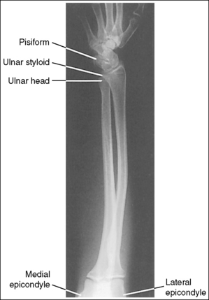
Image 65
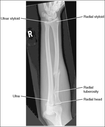
Image 67
• Distal forearm positioning for fracture. Patients with known or suspected fractures may be unable to position both the wrist and elbow joints into an AP projection simultaneously. In such cases, position the joint closer to the fracture in a true position. When the fracture is situated closer to the wrist joint, the wrist joint and distal forearm should meet the requirements for an AP projection, but the elbow and proximal forearm may demonstrate an AP oblique or lateral projection. It may be necessary to position the distal forearm in a PA projection when an AP projection is difficult for the patient. The wrist joint and distal forearm should still be positioned as described earlier (see Image 66).
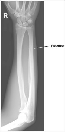
Image 66
The ulnar styloid is projected distally to the midline of the ulnar head.
• The position of the ulnar styloid is determined by the position of the humerus and elbow. When the humerus and elbow positions are adjusted but the wrist position is maintained, it is the ulna that rotates and changes position. Positioning the humeral epicondyles parallel with the IR for the AP projection of the forearm places the ulnar styloid posterior to the head of the ulna. If the elbow is rotated internally and the wrist remains in an AP projection, the ulnar styloid is demonstrated laterally, next to the radius. If the elbow is rotated externally and the wrist remains in an AP projection, the ulnar styloid is demonstrated in profile medially.
The anterior and posterior carpal articulating surfaces of the distal radius are superimposed, and the radioscaphoid and radiolunate joint spaces are open.
• The distal radial carpal articular surface is concave and slants at approximately 11 degrees from posterior to anterior. When the forearm is placed parallel with the IR in an AP projection and the central ray is centered to the midforearm, diverged x-rays record the image much as if the central ray were angled toward the wrist joint. If this angle of divergence is parallel with the AP slant of the distal radius, the resulting image shows superimposed distal radial margins and open radioscaphoid and radiolunate joint spaces.
Proximal Forearm Positioning
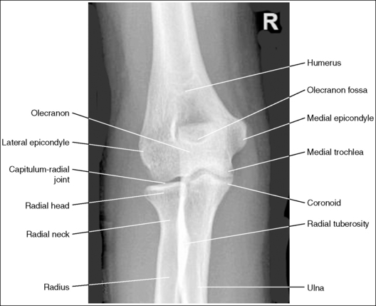
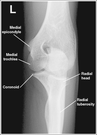
The proximal forearm is positioned in an AP projection. The radial head is superimposed over the lateral aspect of the proximal ulna by approximately 0.25 inch (0.6 cm). If included on the IR, the medial and lateral humeral epicondyles are demonstrated in profile at the extreme medial and lateral edges of the distal humerus.
• An AP proximal forearm projection is obtained by palpating the humeral epicondyles and aligning them parallel with the IR, placing the proximal radius anterior to the ulna (see Figure 4-59).
• Detecting proximal forearm rotation: Proximal forearm rotation results when the humeral epicondyles are poorly positioned. Rotation can be identified on the image when the radial head demonstrates more or less than 0.25 inch (0.6 cm) superimposition on the ulna and when the humeral epicondyles are not visualized in profile. When more than 0.25 inch (0.6 cm) of the radial head is superimposed over the ulna, the elbow has been internally rotated (see Image 74). When less than 0.25 inch (0.6 cm) of radial head is superimposed over the ulna, the elbow has been externally rotated (see Image 67).
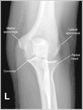
Image 74
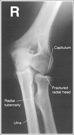
• Proximal forearm positioning for fracture. Patients with known or suspected fractures may be unable to position both the wrist and elbow joint into an AP projection simultaneously. In such cases, position the joint closer to the fracture in the truer position. When the fracture is situated closer to the elbow joint, the elbow joint and proximal forearm should meet the requirements for an AP projection, whereas the wrist and distal forearm may demonstrate obliquity.
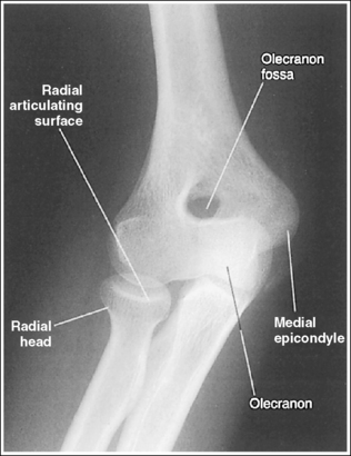
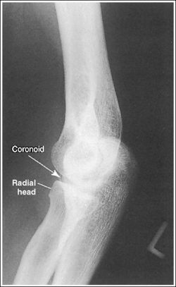
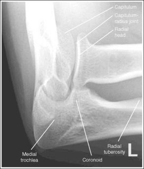
The capitulum-radius joint is either partially or completely closed, and the radial head articulating surface is demonstrated. The olecranon process is situated within the olecranon fossa, and the coronoid process is visible on end.
• The anatomical relationships of the elbow on an AP forearm projection are slightly different from those on an AP elbow projection because of the difference in centering of the central ray. The central ray is placed directly over the elbow joint for an AP elbow projection but is centered distally to the elbow joint, at the midforearm, for an AP forearm projection. With distal centering, diverged rays record the elbow joint image instead of straight central rays, much the same as if the central ray were angled toward the elbow joint. Imaging the elbow with diverged rays projects the radial head into the capitulum-radius joint and causes the anterior margin of the radial head to project beyond the posterior margin, demonstrating its articulating surface.
• Effect of elbow flexion. The positions of the olecranon process and fossa and the coronoid process are determined by the amount of elbow flexion. Accurate forearm positioning requires us to position the elbow in full extension, which places the olecranon process within the olecranon fossa and demonstrates the coronoid process on end. When a forearm image is taken with the elbow flexed and the proximal humerus elevated (Figure 4-60), the olecranon process moves away from the olecranon fossa and the coronoid process shifts proximally. How far the olecranon process is from the fossa depends on the degree of elbow flexion. The greater the elbow flexion, the farther the olecranon process is positioned away from the fossa and the more foreshortened is the distal humerus.
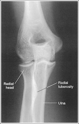
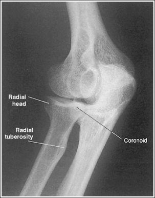
The radial tuberosity is demonstrated in profile medially, and the radius and ulna appear parallel.
• When the distal humerus is positioned with the epicondyles parallel with the IR, the relationship of the radius and ulna is controlled by wrist positioning. To place the radius and ulna parallel and the radial tuberosity in profile medially, position the wrist and hand in an AP projection. When the hand and wrist are pronated, the radius crosses over the ulna, and the radial tuberosity is rotated posteriorly, out of profile (see Image 68).
Image 68
Anteroposterior Forearm Projection Analysis
The humeral epicondyles are demonstrated in profile, and the ulnar styloid is demonstrated distal to the midline of the ulnar head. The elbow has been accurately positioned. The first and second metacarpal bases and the laterally located carpal bones are superimposed, and the medially located carpal bones and pisiform are well demonstrated. The radial styloid is not visible in profile. The wrist was internally rotated.
Correction
While maintaining the AP projection of the elbow, rotate the wrist and hand externally until the hand is supinated and the wrist is in an AP projection.
Analysis
A fracture is located at the distal forearm. The wrist demonstrates a PA projection, whereas the elbow is in a lateral projection.
Correction
Because the joint closer to the fracture is in the true projection, no repositioning movement is needed.
Analysis
The radial styloid is not demonstrated in profile, the laterally located first and second metacarpal bases and carpal bones are superimposed, and the medially located carpals are better demonstrated. The wrist was internally rotated. Less than 0.25 inch (0.6 cm) of the radial head is superimposed over the ulna. The elbow was externally rotated.
Correction
Rotate the wrist and hand externally until they are in an AP projection, and rotate the elbow internally until the humeral epicondyles are parallel with the IR.
Analysis
The radius and ulna are not parallel. The radius is crossed over the ulna, and the radial tuberosity is not demonstrated in profile. For this image, the elbow is in an AP projection but the wrist and hand are positioned in a PA projection. The distal forearm and wrist joint were not included on the image.
FOREARM: LATERAL PROJECTION (LATEROMEDIAL)
See Figure 4-61 and Box 4-17.

Density is uniform across the entire forearm, and contrast and density are adequate to demonstrate the elbow fat structures.
• Anode heel effect. To use the anode heel effect to obtain uniform density across the forearm, position the thinner wrist (distal forearm) at the anode end of the tube and the thicker elbow (proximal forearm) at the cathode end. Set an exposure (mAs) that will adequately demonstrate the midpoint of the forearm.
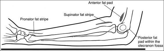
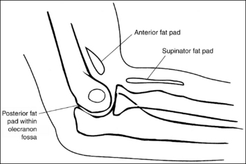
• Soft tissue structures on lateral forearm projection. Soft tissue structures of interest are the anterior and posterior fat pads and the supinator fat stripe at the elbow and pronator fat stripe at the wrist (Figure 4-62). The elbow's anterior fat pad is situated anterior to the distal humerus, and the elbow's supinator fat stripe is visible parallel to the anterior aspect of the proximal radius. A change in the shape or placement of these fat structures indicates joint effusion and elbow injury. The elbow's posterior fat pad is normally obscured on a negative lateral forearm image because of its location within the olecranon fossa. On elbow injury, joint effusion pushes this pad out of the fossa, allowing it to be visualized proximally and posterior to the olecranon process. The wrist's pronator fat stripe is demonstrated parallel to the anterior surface of the distal radius. Bowing or obliteration of this fat stripe may be the only indication of subtle radial fractures.
The forearm midpoint is at the center of the exposure field. The radius and ulna, wrist and elbow joints, and forearm soft tissue are included within the collimated field.
• A perpendicular central ray is centered to the midpoint of the forearm to place the forearm in the center of the image.
When the wrist and elbow joints are included on the image, the degree of radiation beam divergence used to image a long body part needs to be considered (Figure 4-63).
• IR length for the forearm. Choose an IR that is long enough to allow at least 1 inch (2.5 cm) of IR to extend beyond each joint space; half of a 14- × 17-inch (35- × 44-cm) screen-film or computed radiography IR placed lengthwise should be adequate. To ensure that the IR extends beyond the elbow, palpate the medial epicondyle, which is located 0.75 inch (2 cm) proximal to the elbow joint. To ensure that the IR extends beyond the wrist joint, palpate the base of the first metacarpal; the wrist joint is located just proximal to this base.
• Central ray centering and collimation. Once the forearm is accurately positioned in relation to the IR, center the central ray to the midpoint of the forearm, and open the longitudinal collimation field until it extends just beyond the elbow and wrist joints. If collimation does not extend beyond the joints, adjust the centering point of the central ray until both the elbow and the wrist joint are included within the collimated field without demonstrating an excessive field beyond them. Transverse collimation should be within 0.5 inch (1.25 cm) of the forearm skin line.
Distal Forearm Positioning
The distal forearm is in a lateral projection. The anterior aspects of the distal scaphoid and pisiform are aligned with each other, and the distal scaphoid is demonstrated slightly distal to the pisiform. The distal radius and ulna are superimposed.
• A lateral wrist and distal forearm projection is obtained by externally rotating the wrist into a lateral projection with its ulnar aspect against the IR (Figure 4-64). To ensure true lateral positioning, place the palmar aspect of your thumb and forefinger against the anterior and posterior aspects of the patient's wrist joint. Then adjust the rotation until your thumb and finger are aligned perpendicularly to the IR.

• Distal forearm positioning for fracture. Patients with known or suspected fractures may be unable to position both the wrist and elbow joint into a lateral projection simultaneously. In such cases, position the joint closer to the fracture in a true position and position the other joint as close as possible to the true position (see Image 69).

Image 69
• Verifying a lateral forearm projection. The pisiform and distal scaphoid relationship can be used to discern whether a true lateral wrist and distal forearm are demonstrated. On a lateral forearm projection with accurate positioning, these two bones should be visible anterior to the capitate and lunate, with their anterior aspects aligned and the distal scaphoid projecting distally to the pisiform. It is the diverged x-ray beams used to image the pisiform and scaphoid that cause the distal scaphoid to be projected distally to the pisiform. When the wrist and distal forearm are rotated, the anterior alignment of the scaphoid and pisiform, as well as of the radius and ulna, changes. If the wrist and distal forearm have been externally rotated, the pisiform is visible anterior to the distal scaphoid, and the ulna appears anterior to the radius. The radial tuberosity will also be visible anteriorly if the elbow is placed in a true lateral projection (see Image 70). If the wrist and distal forearm have been internally rotated, the distal scaphoid is visible anterior to the pisiform and the radius appears anterior to the ulna (see Image 71).
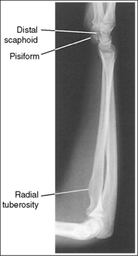
Image 70

Image 71
The ulnar styloid is demonstrated in profile posteriorly.
• When the humerus and elbow are mispositioned, the placement of the ulna changes. The ulnar styloid is put in profile by placing the elbow in a lateral position and abducting the humerus until it is parallel with the IR, aligning the entire arm on the same horizontal plane. If the humerus is not abducted, nor the elbow positioned laterally, the ulnar styloid is positioned medially, out of profile.
Proximal Forearm and Distal Humerus Positioning
• When the elbow is flexed 90 degrees, displacement of the anterior or posterior fat pads can be used as a sign to determine diagnosis. Poor elbow positioning, however, also displaces these fat pads and consequently simulates joint pathology. When the elbow is extended, nonpathologic displacement of the anterior and posterior fat pads may result from intraarticular pressure and the olecranon's position within the olecranon fossa.
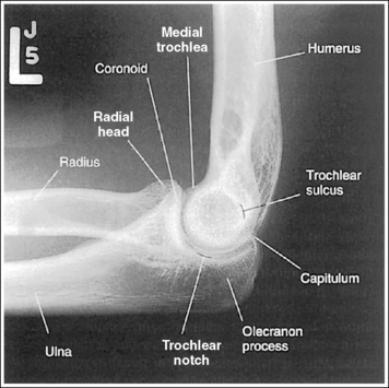
The distal humerus is in a lateral projection. The distal humerus demonstrates three concentric (having the same center) arcs, formed by the trochlear sulcus, capitulum, and medial aspect of the trochlea. The elbow joint space is open, and the radial head is superimposed over the coronoid process.
• A lateral proximal forearm projection is obtained by placing the elbow in a lateral projection and abducting the humerus until it is parallel with the IR, thereby putting the entire arm on the same horizontal plane. The wrist and hand are then placed in a lateral projection, and the medial (ulnar) aspect of the forearm rests against the IR (see Figure 4-64). Even though the capitulum is placed anterior to the medial trochlea and the humeral epicondyles are not superimposed for this position, an open joint space may still be obtained. Because the central ray is centered to the midforearm, the diverged x-rays used to image the distal humerus align parallel with the slant of the capitulum and medial trochlea (see Figure 4-63). The result of this parallelism is an open elbow joint space.
• Effect of muscular or thick forearm. Because the patient's forearm rests on its ulnar surface, the size of the proximal and distal forearm affects the appearance of the elbow joint space. For a patient with a muscular or thick proximal forearm, which is therefore elevated higher than the distal forearm, the capitulum is positioned too far anteriorly and the medial trochlea too posteriorly to align with the x-ray beam divergence. The resulting image demonstrates a closed elbow joint space, and the radial head is positioned distal to the coronoid process (see Image 72).
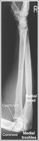
Image 72
• Forearm and humeral positioning for fracture. Patients with known or suspected fractures may be unable to position both the wrist and elbow joint into a lateral projection simultaneously. In such cases, position the joint closer to the fracture in the true position. When the fracture is situated closer to the elbow joint, the elbow joint and proximal forearm should meet the requirements for a lateral projection, whereas the wrist and distal forearm should be positioned as close as possible to a lateral projection.
• Effect of poor humeral positioning. Misalignment of the capitulum and medial trochlea, as well as of the radial head and coronoid process, is also the result of poor humeral positioning. When the distal surface of the capitulum appears quite distal to the distal surface of the medial trochlea and the radial head is positioned posterior to the coronoid process, the proximal humerus was elevated (Figure 4-65; see Image 73). When the distal surface of the capitulum appears proximal to the distal surface of the medial trochlea and the radial head is positioned too anteriorly on the coronoid process, the proximal humerus was positioned lower than the distal humerus.
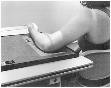
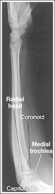
Image 73
Lateral Forearm Projection Analysis
A fracture is located at the distal forearm. The wrist demonstrates a lateral projection, but the elbow is rotated.
Correction
Because the joint closer to the fracture is in the true lateral projection, no repositioning movement is needed.
Analysis
On this image the elbow has been accurately positioned. The pisiform is demonstrated anterior to the scaphoid and the radial tuberosity is shown anteriorly in profile, indicating that the wrist and distal forearm were slightly externally rotated.
Correction
While maintaining accurate elbow positioning, internally rotate the wrist and distal forearm into a lateral position. This movement will rotate the scaphoid toward the pisiform, aligning their anterior aspects.
Analysis
The distal scaphoid is anterior to the pisiform and the radius is anterior to the ulna, indicating that the wrist and hand were internally rotated.
Correction
If the patient is able, externally rotate the hand and wrist until they are in a true lateral projection. This may not be possible because of the radial fracture.
Analysis
The capitulum is positioned too far anterior to the medial trochlea, and the radial head is positioned distal to the coronoid process. The proximal forearm was elevated higher than the distal forearm, possibly because the patient has a muscular or thick proximal forearm.
Correction
Raise the distal forearm until the forearm is positioned parallel with the IR, or, if the patient's proximal forearm is muscular or thick, no positioning adjustment is needed.
Analysis
The wrist is accurately positioned. The distal end of the capitulum is shown distal to the medial trochlea, and the radial head is posterior to the coronoid process. The proximal humerus was elevated as shown in Figure 4-65.
ELBOW: ANTEROPOSTERIOR PROJECTION
See Figure 4-66 and Box 4-18.
The elbow is positioned in an AP projection. The medial and lateral humeral epicondyles are demonstrated in profile at the extreme medial and lateral edges of the distal humerus, and the radial head is superimposed over the lateral aspect of the proximal ulna by approximately 0.25 inch (0.6 cm). The coronoid process is demonstrated on end.
• An AP projection of the elbow is obtained by supinating the patient's hand and externally rotating the forearm and humerus until an imaginary line drawn between the humeral epicondyles is parallel with the IR (Figure 4-67). This positioning places the proximal radius anterior to the ulna.
• Detecting elbow rotation. Rotation of the elbow is a result of poor humeral epicondyle positioning and can be identified on an image when (1) the epicondyles are not visualized in profile, (2) the radial head is demonstrated with more or less than 0.25 inch (0.6 cm) superimposition of the ulna, and (3) the coronoid process is seen in profile. The smaller, lateral humeral epicondyle is more sensitive to rotation, moving out of profile with only a slight degree of elbow rotation. If the epicondyles are not demonstrated in profile, evaluate the degree of radial head superimposition of the ulna to determine how to reposition for an AP projection. If more than 0.25 inch (0.6 cm) of radial head is superimposed over the ulna, the elbow has been internally rotated (see Image 74). If less than 0.25 inch (0.6 cm) of the radial head is superimposed over the ulna, the elbow has been externally rotated (see Images 75 and 76).
Image 75
The radial tuberosity is demonstrated in profile medially, and the radius and ulna are parallel.
• The alignment of the radius and ulna is determined by the position of the humerus and the wrist. When the humerus is positioned with the humeral epicondyles parallel with the IR, the radial and ulnar relationship can be adjusted with wrist rotation. For an AP projection of the elbow, the hand and wrist should also be positioned in an AP projection by supinating the hand. This positioning places the radial tuberosity medially in profile and eliminates crossing of the radius and ulna. As the hand and wrist are pronated, the radius crosses over the ulna, and the radial tuberosity is rotated posteriorly, out of profile (see Image 77).
Image 77
The capitulum-radius joint is open, the radial head articulating surface is not demonstrated, the olecranon process is situated within the olecranon fossa, and the coronoid process is demonstrated on end.
• You must use accurate central ray placement and position the forearm parallel with the IR to obtain an open capitulum-radius joint space. When the central ray is centered proximal to the elbow joint space, the capitulum is projected into the joint; when the central ray is centered distal to the elbow joint, the radial head is projected into the joint space (see Image 78). Poor central ray placement also distorts the radial head, causing its articulating surface to be demonstrated. The degree of joint closure depends on how far the central ray is positioned from the elbow joint. The farther away from the joint the central ray is centered, the more the capitulum-radial joint space is obscured and the more the radial head articulating surface is demonstrated.
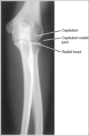
Image 78
• Effect of elbow flexion. Flexion of the elbow joint also distorts the AP elbow projection. With elbow flexion, the capitulum-radial joint closes, the olecranon process moves away from the olecranon fossa, and the coronoid process shifts proximally. How a flexed elbow is positioned with respect to the IR determines which elbow structures are distorted on the image. If a flexed elbow is resting on the posterior point of the olecranon, with the proximal humerus and the distal forearm elevated as shown in Figure 4-68, both the humerus and the forearm are foreshortened and the capitulum-radial joint is obscured (see Image 79). Foreshortening of the proximal humerus is indicated on the image by an oval olecranon fossa that is clearly demonstrated, without the olecranon within it. Foreshortening of the distal forearm is demonstrated if the radial head articulating surface is imaged partially on end. The severity of the distortion increases with increased elbow flexion.

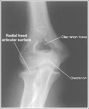
Image 79
• Compensating for a nonextendable elbow. An elbow that cannot be fully extended should be imaged using separate exposures to image the distal humerus and the proximal forearm. Figure 4-69demonstrates how the patient should be positioned for an undistorted AP distal humerus image to be obtained. Note that the humerus is placed parallel with the IR. The resulting image demonstrates an undistorted image of the distal humerus, whereas the proximal forearm is severely distorted and the capitulum-radial joint space is obscured (see Image 80). Figure 4-70 demonstrates how the patient should be positioned for an undistorted AP proximal forearm projection to be obtained. Note that the forearm is placed parallel with the IR. The resulting image demonstrates an undistorted image of the proximal forearm and an open capitulum-radial joint, but the distal humerus is severely distorted (see Image 81). The capitulum-radial joint space is visible on the image only if the forearm is positioned parallel with the IR.

Figure 4-69 Patient positioning for nonextendable AP elbow projection—humerus parallel with image receptor.
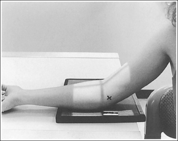
Figure 4-70 Patient positioning for nonextendable AP elbow projection—forearm parallel with image receptor.
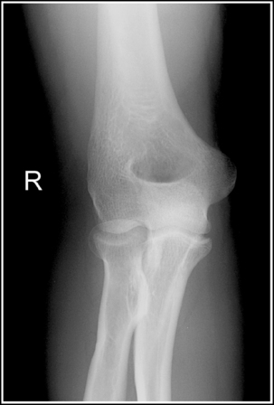
Image 80
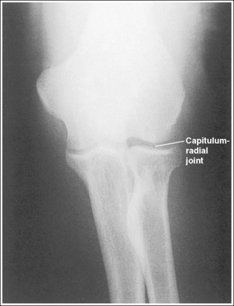
Image 81
The elbow joint is at the center of the exposure field. The elbow joint, one fourth of the proximal forearm and distal humerus, and the lateral soft tissue are included within the collimated field.
• The elbow joint is located 0.75 inch (2 cm) distal to the easily palpable medial epicondyle. To obtain an image of the elbow joint with the least amount of distortion, place a perpendicular central ray at this level and centered to the midelbow. Open longitudinal collimation to include one fourth of the proximal forearm and distal humerus. Transverse collimation should be within 0.5 inch (1.25 cm) of the elbow skin line.
• Half of a 10- × 12-inch (24- × 30-cm) detailed screen-film IR placed crosswise or an 8- × 10-inch (18- × 24-cm) computed radiography IR placed lengthwise should be adequate to include all the required anatomic structures.
Anteroposterior Elbow Projection Analysis
The humeral epicondyles are not in profile. The radial head is superimposing more than 0.25 inch (0.6 cm) of the ulna, and the coronoid process is visible medially. The elbow was internally rotated. The capitulum-radial joint space is closed. The distal forearm was slightly elevated.
Correction
Rotate the elbow externally until the humeral epicondyles are parallel with the IR, and position the forearm parallel with the IR.
Analysis
The humeral epicondyles are not in profile, and less than 0.25 inch (0.6 cm) of the radial head is superimposing the ulna. The image was taken with the elbow in external rotation.
Analysis
The humeral epicondyles are not in profile, and less than 0.25 inch (0.6 cm) of the radial head is superimposing the ulna. The image was taken with the elbow in external rotation. The olecranon is not situated in the olecranon fossa. The elbow was in slight flexion.
Correction
Rotate the elbow internally until the humeral epicondyles are parallel with the IR. If possible, fully extend the elbow. If the patient is unable to extend the elbow, this is an acceptable image of the distal humerus. A second AP projection of the elbow should be taken with the forearm positioned parallel with the IR.
Analysis
The radius is crossed over the ulna, and the radial tuberosity is not demonstrated in profile. The hand and wrist were pronated for this image.
Analysis
The capitulum-radial joint space is closed, and the radial head articulating surface is demonstrated. The central ray was centered distal to the joint space.
Correction
Center the central ray to the midelbow at a level 0.75 inch (2 cm) distal to the medial epicondyle.
Analysis
The capitulum-radial joint space is closed, and the proximal forearm and distal humerus are foreshortened. The elbow was flexed (40 degrees), and the arm was resting on the posterior point of the elbow with the distal forearm and proximal humerus elevated.
Correction
If possible, fully extend the elbow. If the patient is unable to extend the elbow, take two nonextendable AP projections, one with the forearm and one with the humerus positioned parallel with the IR, as shown in Figures 4-69 and 4-70.
Analysis
The distal humerus is demonstrated without foreshortening, but the proximal forearm is severely distorted. The humerus was positioned parallel with the IR, but the distal forearm was elevated, as shown in Figure 4-69.
Correction
If possible, fully extend the elbow. If the patient is unable to extend the elbow, this is an acceptable image of the distal humerus. A second AP projection of the elbow should be taken with the forearm positioned parallel with the IR, as shown in Figure 4-70.
Analysis
The proximal forearm is demonstrated without foreshortening, and the capitulum-radial joint space is open, but the distal humerus is severely distorted. The forearm was positioned parallel with the IR, whereas the proximal humerus was elevated, as shown in Figure 4-70.
Correction
If possible, fully extend the elbow. If the patient is unable to extend the elbow, this is an acceptable image of the proximal forearm. A second AP projection of the elbow should be taken with the humerus positioned parallel with the IR, as shown in Figure 4-69.
ELBOW: ANTEROPOSTERIOR OBLIQUE PROJECTIONS (INTERNAL AND EXTERNAL ROTATION)
See Figures 4-71 and 4-72 and Box 4-19.
External AP oblique projection: The capitulum-radial joint is open, and the radial head articulating surface is not demonstrated.
Internal AP oblique projection: The trochlea-coronoid process joint is open, and the coronoid process articulating surface is not demonstrated.
• To obtain open capitulum-radial and trochlear-coronoid process joint spaces, you must use accurate central ray placement and position the elbow with the forearm parallel with the IR. When the central ray is centered proximal to the elbow joint spaces, the structures of the distal humerus are projected into the joint; when the central ray is centered distal to the elbow joint, the structures of the proximal forearm are projected into the joint space. Poor central ray positioning also distorts the radial head and coronoid process, causing their articulating surface to be visualized. The degree of joint closure and radial head and coronoid process distortion depends on how far the central ray is positioned from the elbow joint. The farther away from the joint the central ray is centered, the more the joint spaces will be obscured, and the more the articulating surfaces of the radial head and coronoid process will be demonstrated.
• Effect of elbow flexion. Flexion of the elbow joint also distorts the AP oblique elbow projection. With elbow flexion, the olecranon process moves away from the olecranon fossa and the coronoid process shifts proximally. How the flexed elbow is positioned with respect to the IR determines which elbow structures are distorted on the image. If a flexed elbow is resting on the posterior point of the olecranon, with the proximal humerus and the distal forearm elevated, both the humerus and the forearm are foreshortened and the capitulum-radial and trochlear-coronoid process joints are obscured. Foreshortening of the proximal humerus is demonstrated on an image by an oval olecranon fossa that is clearly shown but without the olecranon process within it. Foreshortening of the distal forearm is demonstrated on the image if the radial head and trochlear articulating surfaces are visualized.
The severity of the distortion depends on the degree of elbow flexion. If the humerus is positioned parallel with the IR and the distal forearm is elevated, the image shows an undistorted distal humerus, but the proximal forearm is severely distorted and the capitulum-radial joint is obscured (see Image 82). If the forearm is positioned parallel with the IR and the proximal humerus is elevated, the image shows an undistorted proximal forearm and open capitulum-radial and trochlear-coronoid process joints, but the distal humerus is severely distorted.
• Positioning of the nonextendable elbow. For AP oblique elbow projections, if the patient's condition prevents full elbow extension, the anatomic structure (forearm or humerus) of interest should be positioned parallel with the IR. If the radial head or coronoid process is of interest, position the forearm parallel with the IR (Figure 4-73). If the capitulum or medial trochlea is of interest, position the humerus parallel with the IR. The degree and direction of elbow obliquity are the same as those used for an extended elbow.

Internally Rotated AP Oblique Projection
The elbow has been internally rotated 45 degrees. The coronoid process, the trochlear notch, and the medial aspect of the trochlea are demonstrated in profile. The trochlear-coronoid process articulation is open, and the radial head and neck are superimposed over the ulna.
• An accurately positioned internally rotated AP oblique elbow projection is obtained by placing the arm in an AP elbow projection and then internally rotating the hand and humerus until the humeral epicondyles are at a 45-degree angle to the IR (Figure 4-74). When the elbow obliquity is correct, the coronoid process is demonstrated in profile and the radial head and tuberosity are superimposed over the ulna. If the humeral epicondyles are at less than 45 degrees of obliquity, the radial head is demonstrated lateral to the coronoid process and does not entirely superimpose the ulna (see Image 83). If the humeral epicondyles are at more than 45 degrees of obliquity, the radial head is partially visualized anterior to the coronoid process (see Image 84).


Externally Rotated Oblique Projection
The elbow has been externally rotated 45 degrees. The capitulum and radial tuberosity are demonstrated in profile, the radial head, neck, and tuberosity are visualized without superimposing the ulna, and the radioulnar articulation is demonstrated.
• Accurate positioning for an externally rotated AP oblique elbow projection is achieved by positioning the arm in an AP projection and then externally rotating the humerus and forearm until the humeral epicondyles form a 45-degree angle with the IR (Figure 4-75). This positioning rotates the radius away from the ulna, demonstrating it without superimposition. If the humeral epicondyles are at less than 45 degrees of obliquity, the radial head and tuberosity still partially superimpose the ulna (see Image 85). If the humeral epicondyles are at more than 45 degrees of obliquity, the coronoid process is partially superimposed over the radial head, and the radial neck and tuberosity are free of superimposition; the radial tuberosity is no longer in profile (see Image 86).

The elbow joint is at the center of the exposure field. The elbow joint, one fourth of the proximal forearm and distal humerus, and surrounding soft tissue are included within the collimated field.
• The elbow joint is located 0.75 inch (2 cm) distal to the easily palpable medial humeral epicondyle. To obtain an undistorted image of the elbow joint, place a perpendicular central ray at this level and centered to the midelbow. Open longitudinal collimation to include one fourth of the proximal forearm and distal humerus. Transverse collimation should be within 0.5 inch (1.25 cm) of the elbow skin line.
• Half of a 10- × 12-inch (24- × 30-cm) detailed screen-film IR placed crosswise or an 8- ×10-inch (18- × 24-cm) computed radiography IR placed lengthwise should be adequate to include all the required anatomic structures.
AP Oblique Elbow Projection Analysis
The olecranon process is drawn slightly away from the olecranon fossa, the capitulum-radial joint space is closed, and the radial articulating surface is demonstrated. The forearm was not positioned parallel with the IR.
Correction
If possible, fully extend the elbow. If the patient is unable to fully extend the elbow and the radial head is of interest, position the forearm parallel with the IR and allow the proximal humerus to be elevated, as shown in Figure 4-73.
Analysis
The radial head is demonstrated lateral to the coronoid process without complete superimposition of the ulna, and the most proximal aspect of the olecranon is not demonstrated in profile. The degree of elbow obliquity is less than 45 degrees.
Correction
Increase the degree of internal obliquity until the humeral epicondyles are angled at 45 degrees with the IR.
Analysis
The radial head is partially demonstrated anterior to the coronoid process, without complete superimposition of the ulna. The degree of elbow obliquity is more than 45 degrees.
Correction
Decrease the degree of internal obliquity until the humeral epicondyles are angled at 45 degrees with the IR.
Analysis
The radial head and tuberosity are partially superimposed over the ulna, and the radioulnar articulation is obscured. The degree of elbow obliquity is less than 45 degrees. The forearm was not positioned parallel with the IR.
Correction
Increase the degree of external obliquity until the humeral epicondyles are angled at 45 degrees with the IR, and position the forearm parallel with the IR.
ELBOW: LATERAL PROJECTION (LATEROMEDIAL)
See Figure 4-76 and Box 4-20.
Contrast and density are adequate to demonstrate the anterior, posterior, and supinator fat pads, surrounding soft tissue, and bony structures.
• Fat pads on lateral elbow projection. To evaluate a lateral elbow projection, the reviewer not only analyzes the bony structure, but also studies the placement of the soft tissue fat pads. Three fat pads of interest are present on a lateral elbow projection, the anterior and posterior fat pads and the supinator fat stripe. The anterior fat pad should routinely be seen on all lateral elbow projections when adequate exposure factors are used. This pad is formed by the superimposed coronoid process and radial pads and is situated immediately anterior to the distal humerus (Figure 4-77). A change in the shape or placement of the anterior fat pad may indicate joint effusion and elbow injury. The posterior fat pad is normally obscured on a negative lateral elbow projection because of its location within the olecranon fossa. When an injury occurs, joint effusion pushes this pad out of the fossa, allowing it to be visualized proximal and posterior to the olecranon fossa. The supinator fat stripe is visible parallel to the anterior aspect of the proximal radius (see Figure 4-77). Displacement of this fat stripe is useful for diagnosing fractures of the radial head and neck.
The elbow is flexed 90 degrees.
• When the elbow is flexed 90 degrees, the forearm can be elevated to align the anatomic structures of the distal humerus properly, and displacement of the anterior and posterior fat pads can be used as signs to determine diagnosis. If the elbow is not adequately flexed, these fat pads can be displaced by poor positioning instead of joint pathology, interfering with their diagnostic usefulness. When the arm is extended, nonpathologic displacement of the anterior fat pad results from intraarticular pressure placed on the joint. Nonpathologic displacement of the posterior fat pad is a result of positioning of the olecranon within the olecranon fossa, which causes proximal and posterior displacement of the pad (see Image 87).

Image 87
The elbow is in a lateral projection. The distal humerus demonstrates three concentric arcs, which are formed by the trochlear sulcus, capitulum, and medial trochlea. The elbow joint space is open, and the radial head is superimposed over the coronoid process.
• A lateral elbow projection is obtained when the humeral epicondyles are positioned directly on top of each other, placing an imaginary line drawn between them perpendicular to the IR. To obtain this humeral epicondyle positioning, place the humerus parallel with the IR and elevate the distal forearm until the palpable medial and lateral epicondyles are superimposed (Figure 4-78). This positioning aligns the trochlear sulcus, capitulum, and medial trochlea into three concentric (having the same center) arcs (Figure 4-79). The trochlear sulcus is the small center arc. It moves very little when a positional change is made and works like a pivoting point between the capitulum and medial aspect of the trochlea. The largest of the arcs is the medial aspect of the trochlea. It is demonstrated very close to and slightly superimposed on the curve of the trochlear notch. The intermediate-sized arc is the capitulum. When these three arcs are in accurate alignment, the elbow joint is visualized as an open space and the anterior and proximal surfaces of the radial head and coronoid process are aligned.
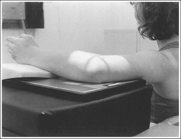
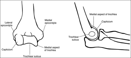
Figure 4-79 AP (left) and lateral (right) images showing anatomy of the distal humerus. (From Martensen K III: The elbow, In-Service Reviews in Radiologic Technology, 14[11], 1992.)
• Importance of accurate positioning. The distal humerus, radial head, and coronoid process are misaligned when the proximal humerus and distal forearm are inaccurately positioned. Proximal humerus positioning determines the alignment of the distal surfaces of the capitulum and medial trochlea, whereas distal forearm positioning determines the AP alignment of the capitulum and medial trochlea. Proximal humerus and distal forearm positioning also determines the alignment of the radial head and coronoid process. Depression or elevation of the proximal humerus moves the radial head anteriorly or posteriorly on the coronoid process, respectively. Depression or elevation of the distal forearm shifts the radial head distally or proximally, respectively, to the coronoid process. To help understand how the distal humerus and radial head move together, remember that ligaments connect the capitulum and the radial head, so any movement in one causes an equal amount of movement in the other. Precise positioning is a must to obtain a true lateral elbow projection. It takes only a small amount of inaccurate positioning to misalign the distal humerus and close the elbow joint space.
• Mispositioning of the proximal humerus. If the proximal humerus is elevated (Figure 4-80), the radial head is positioned too far posteriorly on the coronoid process, and the distal capitulum surface is demonstrated too far distal to the distal surface of the medial trochlea (see Image 88). If the proximal humerus is positioned lower than the distal humerus (Figure 4-81), the radial head is positioned too far anteriorly on the coronoid process and the distal capitulum surface is demonstrated too far proximal to the distal medial trochlear surface (see Images 89, 90, and 96).
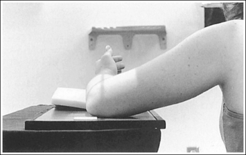
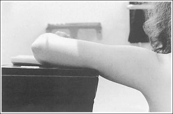
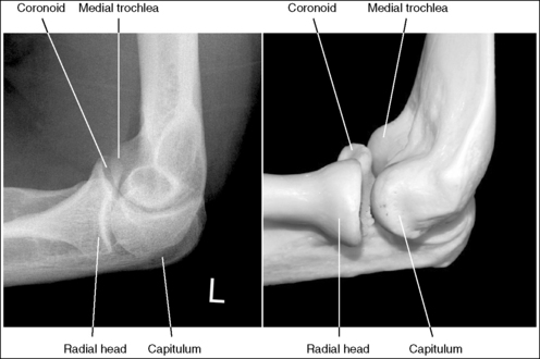
Image 88
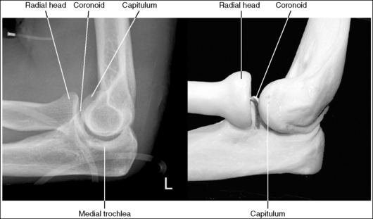
Image 89
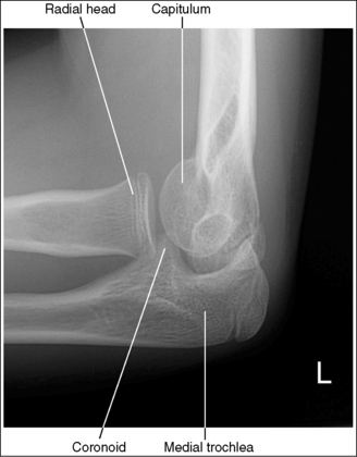
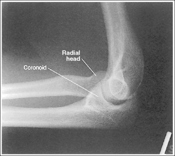
Image 96
• Mispositioning of the distal forearm. When the distal forearm is positioned too low (Figure 4-82), the image shows the radial head distal to the coronoid process and the capitulum too far anterior to the medial trochlea (Images 91 and 92). When the distal forearm is positioned too high (Figure 4-83), the image shows the radial head proximal to the coronoid process and the capitulum too far posterior to the medial trochlea (see Images 93 and 96). Carefully evaluate images that show poor positioning. Often, both forearm and humeral corrections are needed to obtain accurate positioning.

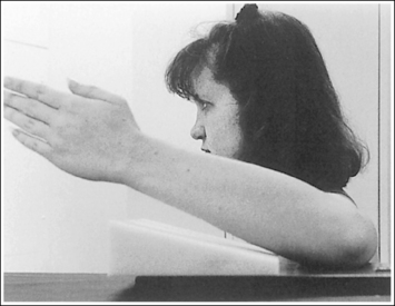
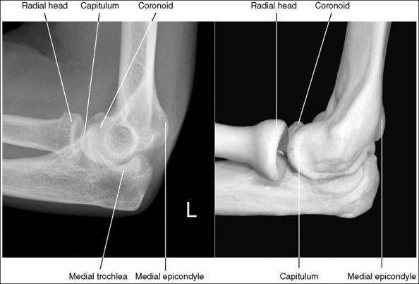
Image 91

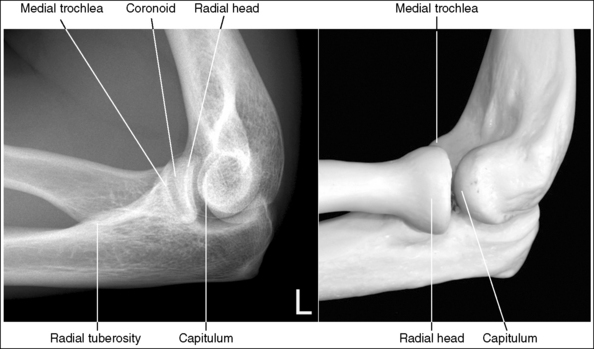
Image 93
The radial tuberosity is superimposed by the radius and is not demonstrated in profile.
• Visibility of the radial tuberosity is determined by the position of the wrist and hand. When the wrist and hand are placed in a lateral position, the radial tuberosity is situated on the medial aspect of the radius. Because a lateral elbow projection is taken in a lateromedial projection, the radius is superimposed over the radial tuberosity. If the wrist and hand are not placed in a lateral position, placement of the radial tuberosity changes. When the wrist and hand are supinated (externally rotated), the radial tuberosity is demonstrated in profile anteriorly (see Image 94). Pronation (internal rotation) of the wrist and hand shows the radial tuberosity in profile posteriorly (see Image 95).
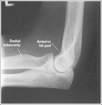
Image 94
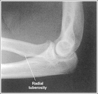
Image 95
• Lateral elbow projections obtained with the different hand and wrist positions just described are often taken to study the circumference of the radial head and neck for fractures; they are referred to as radial head images.
The elbow joint is at the center of the exposure field. The elbow joint, one fourth of the proximal forearm and distal humerus, and the surrounding soft tissue are included within the collimated field.
• The elbow joint is located 0.75 inch (2 cm) distal to the lateral epicondyle. To obtain an undistorted image of the elbow joint, place a perpendicular central ray at this level and centered to the midelbow. Open longitudinal collimation to include one fourth of the proximal forearm and distal humerus. Transverse collimation should be within 0.5 inch (1.25 cm) of the elbow skin line.
• Half of a 10- × 12-inch (24- × 30-cm) detailed screen-film IR placed crosswise or an 8- × 10-inch (18- × 24-cm) computed radiography IR placed lengthwise should be adequate to include all the required anatomic structures.
Lateral Elbow Projection Analysis
The elbow is extended. The olecranon is positioned within the olecranon fossa, and the posterior fat pad is demonstrated proximal to the olecranon process. The radial tuberosity is demonstrated in profile posteriorly, indicating that the hand and wrist were pronated.
Correction
If possible, flex the elbow 90 degrees. Position the hand and wrist in a lateral position.
Analysis
The radial head is positioned too far posteriorly on the coronoid process and the distal surface of the capitulum is demonstrated too far distally to the distal surface of the medial trochlea. The patient was positioned with the proximal humerus elevated, as shown in Figure 4-80.
Correction
Lower the proximal humerus until the humeral epicondyles are superimposed and the humerus is positioned parallel with the IR. This change will move the capitulum proximally and the medial trochlea distally. Because the capitulum and the trochlea move simultaneously, the amount of adjustment needed is only half the distance demonstrated between where the two distal surfaces should be on a lateral elbow projection with accurate positioning and where they are on this image. On this image this distance is approximately 0.5 inch (1 cm), so the repositioning adjustment needed is only 0.25 inch (0.6 cm).
Analysis
The radial head is positioned anterior on the coronoid process, and the distal surface of the capitulum is too far proximal to the distal surface of the medial trochlea. The patient was positioned with the proximal humerus depressed, as shown in Figure 4-81.
Correction
Elevate the proximal humerus until the humeral epicondyles are superimposed and the humerus is positioned parallel with the IR. Because the radial head and coronoid process, the capitulum, and the trochlea move simultaneously, the amount of adjustment required is only half the distance demonstrated between the two anterior and distal surfaces, respectively.
Analysis
The radial head is positioned anterior and distal to the coronoid process, and the capitulum is too far proximal and anterior to the medial trochlea. The patient was placed with the proximal humerus and distal forearm positioned too low.
Correction
Elevate the proximal humerus and distal forearm until the humeral epicondyles are superimposed.
Analysis
The radial head is distal to the coronoid process, and the capitulum is too far anterior to the medial trochlea. The patient was placed with the distal forearm positioned too close to the IR, as shown in Figure 4-82.
Correction
Elevate the distal forearm until the humeral epicondyles are superimposed. This change will move the capitulum posteriorly and the medial trochlea anteriorly. Because the radial head and coronoid process, capitulum, and trochlea move simultaneously, the amount of adjustment required is only half the distance demonstrated between the two distal and anterior surfaces, respectively.
Analysis
The radial head is distal to the coronoid process, and the capitulum is too far anterior to the medial trochlea. The patient was placed with the distal forearm positioned too close to the IR.
Analysis
The radial head is proximal to the coronoid process, and the capitulum appears too far posterior to the medial trochlea. The patient was positioned with the distal forearm placed too far away from the IR, as shown in Figure 4-83. The radial tuberosity is visible posteriorly. The distal forearm was internally rotated.
Correction
Lower the distal forearm until the humeral epicondyles are superimposed, and internally rotate the distal forearm until the wrist is in a lateral projection.
Analysis
The elbow joint space is open, and the distal humerus demonstrates accurate alignment. The radial tuberosity is demonstrated in profile anteriorly, indicating that the wrist and hand were supinated (externally rotated).
Correction
If the circumference of the radial head and neck is being evaluated and the medial aspect of the radial head in profile is desired, the radial tuberosity should be demonstrated in profile anteriorly and no repositioning movement is needed. If a true lateral elbow image is desired, the distal forearm should be internally rotated until the wrist is in a lateral projection.
Analysis
The elbow joint space is open, and the distal humerus demonstrates accurate alignment. The radial tuberosity is demonstrated in profile posteriorly, indicating that the hand and wrist were pronated (internally rotated).
Correction
If the circumference of the radial head and neck is being evaluated and the medial aspect of the radial head in profile is desired, the radial tuberosity should be seen in profile anteriorly and no repositioning movement is needed. If a true lateral elbow projection is desired, the distal forearm should be externally rotated until the wrist is in a lateral projection.
Analysis
Two positional problems on this image are preventing the distal humerus from demonstrating accurate alignment. The radial head is positioned anteriorly and proximally to the coronoid process, and the capitulum is positioned too far proximally and posteriorly to the medial trochlea. The proximal humerus was positioned too low, and the distal forearm was positioned too high, a combination of the errors shown in Figures 4-81 and 4-83.
ELBOW: AXIOLATERAL PROJECTION (COYLE METHOD)
The radial axiolateral elbow image is a special projection taken when a fracture of the radial head or capitulum is suspected (Figure 4-84 and Box 4-21).
The elbow is flexed 90 degrees.
• If the elbow is flexed 90 degrees, the forearm can be elevated to align the anatomic structures of the distal humerus properly.
The capitulum and medial trochlea are demonstrated without superimposition, and the radial head is superimposed on only the anterior tip of the coronoid process.
• The axiolateral elbow projection is obtained by placing the patient's elbow in a lateral projection, with the humeral epicondyles aligned perpendicular to the IR and placing a 45-degree proximal (toward the shoulder) angle on the central ray (Figure 4-85). It is this humerus and central ray positioning that accurately separates the capitulum and trochlea of the distal humerus and positions the radial head anteriorly to the coronoid process. The combination of positioning and angulation projects the anatomic structures (radial head and capitulum) situated farther from the IR proximal to those structures (coronoid process and medial trochlea) situated closer to the IR.
• Effects of errors in positioning or angulation. If the central ray is angled accurately but the proximal humerus is depressed lower than the distal humerus, the medial trochlea and capitulum cortices are not clearly defined, the coronoid process is free of radial head superimposition, and the radial neck and tuberosity are superimposed by the ulnar supinator crest (a sharp, prominent ridge running along the lateral margin of the ulna that divides the ulna's anterior and posterior surfaces; see Image 97). The same image can result if the patient is accurately positioned but the central ray is angled more than 45 degrees.
Image 97
If the central ray is accurately angled but the proximal humerus is elevated, the medial trochlea demonstrates some capitular superimposition and the radial head is superimposed over a greater portion of the coronoid process (see Image 98). The same image can result if the patient is accurately positioned but the central ray is angled less than 45 degrees.

Image 98
The capitulum-radial joint is open, and the proximal radial head and coronoid process are aligned.
• An accurately aligned radial head and coronoid process and an open capitulum-radial head joint is obtained when the elbow is in a lateral projection. A lateral elbow projection is accomplished when the humeral epicondyles are positioned directly on top of each other, placing them perpendicular to the IR (see Figure 4-85).
• Effect of distal forearm mispositioning. The alignment of the proximal surfaces of the radial head and coronoid process is affected when the distal forearm is positioned. Precise positioning is necessary to obtain accurate alignment. It takes only a small degree of inaccurate positioning to close the capitulum-radius joint. If the distal forearm is positioned too low, the image shows a closed capitulum-radius joint space and shows the capitulum too far anterior to the medial trochlea and the radial head distal to the coronoid process (see Image 99). If the distal forearm is positioned too high, the image shows the capitulum too far posterior to the medial trochlea and the radial head proximal to the coronoid process.

Image 99
The radial head surface of interest is demonstrated in profile.
• The position of the wrist determines which surface of the radial head is placed in profile.
• Effect of wrist position. When the patient's elbow is placed in a lateral projection, wrist rotation causes the radius to rotate around the ulna. This rotation places different radial head surfaces in profile. To determine which surfaces are in profile, one should become familiar with the relationship between the wrist position and visualization of the radial tuberosity. The radial tuberosity is adjacent to the medial aspect of the radius. If the tuberosity is demonstrated, the medial aspect of the radial head is also shown on that same surface and the lateral aspect of the radial head is visible on the opposite surface. If the patient's wrist is positioned in a PA projection, the radial tuberosity and medial radial head are demonstrated posteriorly and the lateral radial head appears in profile anteriorly (see Image 98). If the wrist is in a lateral projection, the radial tuberosity is not demonstrated in profile but is superimposed by the radius. In this position, the anterior radial head is demonstrated in profile anteriorly and the posterior surface is shown in profile posteriorly (see Image 93).
The radial head is at the center of the exposure field. The proximal forearm, distal humerus, and surrounding soft tissue are included within the collimated field.
• To place the radial head in the center of the collimated field, center the central ray 0.75 inch (2 cm) distal (toward the wrist) to the lateral epicondyle. Open the longitudinally and transversely collimated fields to within 0.5 inch (1.25 cm) of the posterior elbow skin line.
• An 8- × 10-inch (18- × 24-cm) detailed screen-film or computed radiography IR placed lengthwise should be adequate to include all the required anatomic structures.
Axiolateral Elbow (Coyle Method) Projection Analysis
The distal medial trochlea and capitulum cortices are not clearly defined, the coronoid process is free of radial head superimposition, and the radial neck and tuberosity are superimposed by the ulnar supinator crest. The proximal humerus was depressed lower than the distal humerus. The radial tuberosity is in partial profile, indicating that the wrist was in an oblique position. The radial tuberosity is in partial profile, indicating that the wrist was in an oblique position.
Correction
Elevate the proximal humerus until the humeral epicondyles are perpendicular to the image. If the image was to demonstrate the anterior and posterior surfaces of the radial head in profile, place the wrist in a lateral position. If it is desired that the anterior and posterior surfaces of the radiation head be demonstrated in profile, place the wrist in a lateral projection.
Analysis
The capitulum-radius joint space is closed, the radial head is demonstrated distal to the coronoid process, and the capitulum is demonstrated too far anterior to the medial trochlea, indicating that the distal forearm was depressed. The radial head is superimposed over more than just the tip of the coronoid process, and the medial trochlea and capitulum would demonstrate slight superimposition if the distal forearm had been accurately positioned; the proximal humerus was elevated. The radial tuberosity is demonstrated in profile posteriorly and the lateral surface of the radial head is demonstrated in profile anteriorly, whereas the medial surface is in profile posteriorly; the wrist was placed in a PA projection.
Correction
Elevate the distal forearm and depress the proximal humerus until the humeral epicondyles are aligned perpendicularly to the IR. If you want the anterior and posterior surfaces of the radial head to be demonstrated in profile, place the wrist in a lateral projection.
Analysis
The capitulum-radius joint space is closed, and the radial head is demonstrated distally to the coronoid process. The radial tuberosity is not demonstrated in profile, the anterior surface of the radial head is in profile anteriorly, and the posterior surface is in profile posteriorly; the wrist was placed in a lateral position.
Correction
Elevate the distal forearm until the humeral epicondyles are aligned perpendicularly to the IR. The amount of movement needed is half the difference between how close the anterior surfaces of the capitulum and medial trochlea should be on a radial head and capitulum image with accurate positioning and how close they are located on this image. If the lateral and medial surfaces of the radial head should be demonstrated in profile, the patient's wrist needs to be placed in a PA projection.
HUMERUS: ANTEROPOSTERIOR PROJECTION
See Figures 4-86 and 4-87 and Box 4-22.
Scatter radiation is controlled. Image density is uniform across the humerus.
• If the patient's upper arm AP thickness measures less than 4 inches (10 cm), a grid is not required. For such a patient, a high-contrast, low-kVp (below 60) technique sufficiently penetrates the bony and soft tissue structures of the humerus without causing excessive scatter radiation to reach the IR and hinder image contrast. If the upper arm measures more than 4 inches (10 cm), a grid should be used, because this thickness would produce enough scatter radiation to affect the image contrast negatively. When a grid is used, increase the kVp to above 70 to penetrate the thicker humerus and provide an adequate scale of contrast. If the technique is manually set, increase the exposure (mAs) by the standard density conversion factor for the grid ratio (number used to express a grid's scatter-eliminating ability) being used to compensate for the scatter and the primary radiation that the grid will absorb.
• Anode heel effect. To take advantage of the anode heel effect, position the thinner elbow (distal humerus) at the anode end of the tube and the thicker (proximal humerus) at the cathode end. Set an exposure (mAs) that will adequately demonstrate the midpoint of the humerus.
The humerus is in an AP projection. The medial and lateral humeral epicondyles are demonstrated in profile, and the radial head and tuberosity are superimposed over the lateral aspect of the proximal ulna by approximately 0.25 inch (0.6 cm). The greater tubercle is demonstrated in profile laterally, the humeral head is demonstrated medially in profile, and the vertical cortical margin of the lesser tubercle is visible approximately halfway between the greater tubercle and the humeral head.
• An AP projection is obtained by placing the patient in a supine or upright AP projection, with the affected arm extended. Supinate the hand and externally rotate the elbow until an imaginary line drawn between the palpable humeral epicondyles is aligned parallel with the IR (Figure 4-88). This positioning places the proximal radius anterior to the ulna, causing the radial head and tuberosity to be superimposed over the lateral ulna by approximately 0.25 inch (0.6 cm), and places the greater tuberosity in profile.

• Detecting humeral rotation. Rotation of the humerus is a result of poor humeral epicondyle positioning. When the humeral epicondyles and the greater tuberosity are not demonstrated in profile, measure the amount of radial head and tuberosity superimposition of the ulna to determine how the patient should be repositioned. If less than 0.25 inch (0.6 cm) of the radial head and tuberosity are superimposed over the ulna, the elbow and humerus have been excessively externally rotated (see Image 100). If more than 0.25 inch (0.6 cm) of the radial head and tubercle are superimposed over the ulna, the elbow and humerus have been internally rotated (see Image 101).
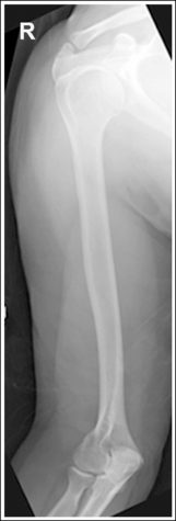
Image 100

Image 101
• Positioning for humeral fracture. When a fracture of the humerus is suspected or a follow-up image is being taken to assess healing of a humeral fracture, the patient's arm should not be externally rotated to obtain the AP projection because external rotation of the forearm increases the risk of radial nerve damage. For such an examination, the joint closer to the fracture should be aligned in the true AP projection. If the fracture site is situated closer to the shoulder joint and the arm cannot be externally rotated, the greater tuberosity is placed in profile by rotating the patient's body toward the affected humerus 35 to 40 degrees (Figure 4-89). Depending on the amount of humeral rotation at the fracture site, the distal humerus may or may not be an AP projection (see Image 102). If the fracture is situated closer to the elbow joint, extend the arm and rotate the patient's body toward the affected humerus until the humeral epicondyles are aligned parallel with the IR. Depending on the amount of humeral rotation at the fracture site, the greater tubercle may or may not be in profile.
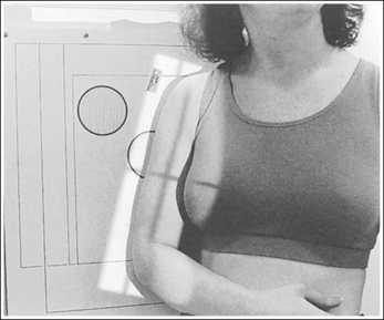
Figure 4-89 Patient positioning for AP humerus projection when fracture is located close to shoulder.

Image 102
The long axis of the humerus is aligned with the long axis of the collimated field.
• If the humerus can remain aligned with the long axis of the IR while including the elbow and shoulder joints, align the long axis of the collimated light field with the long axis of the humerus to allow for tight transverse collimation.
• For many adult humeral projections, it may be necessary to position the humerus diagonally on the IR to include the elbow and shoulder joint. If using screen-film or DR systems for this positioning, the collimator head or tube column should be turned or rotated to align the long axis of the collimated light field with the long axis of the humerus. If a grid is used, the collimator head may be rotated, but do not rotate the tube column or grid cutoff will result. This is not recommended with computed radiography (CR) systems. If the collimator head or tube column cannot be adjusted for a diagonal positioning, leave the transversely collimated field open enough to include the shoulder joint and elbow. With this setup the collimated field includes a large portion of the patient's thorax. Therefore the thorax is exposed to unnecessary radiation but can be protected by use of a contact shield across it. Remember to leave at least 3 inches (7.5 cm) of space between the humeral head and the shield to allow for magnification, so that the shoulder joint is not obscured by the shield (Figure 4-90).
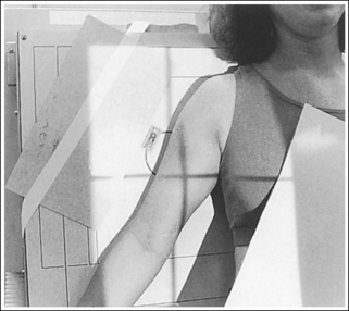
The humeral midpoint is at the center of the exposure field. The shoulder and elbow joints and the lateral humeral soft tissue are included within the collimated field.
• To place the humeral midpoint in the center of the image, palpate the coracoid process and the medial epicondyle and position the central ray halfway between these two palpable landmarks. When the elbow and shoulder joints are included on the image, the degree of radiation beam divergence used for a long body part needs to be considered.
• IR length and positioning: Choose an IR that is long enough to allow at least 1 inch (2.5 cm) of IR to extend beyond each joint space; a 14- × 17-inch (35- × 44-cm) screen-film or computed radiography IR placed lengthwise should be adequate. For a patient with a long humerus, it may be necessary to position the humerus somewhat diagonally on the IR to obtain the needed IR length. For the computed radiography system, it is not advisable to position the part diagonally unless the system is set to handle this alignment. Palpate the two joints to ensure that the IR extends beyond them. The elbow is located approximately 0.75 inch (2 cm) proximal to the medial epicondyle. The shoulder joint is located at the same level as the palpable coracoid.
• Central ray centering and collimation. Once the humerus is accurately positioned with the IR, center a perpendicular central ray to the humeral midpoint, and open the longitudinal collimated field until it extends 1 inch (2.5 cm) beyond the elbow and shoulder joint. If the collimation does not extend beyond both joints, adjust the centering point of the central ray until both the elbow and the shoulder joint are included within the collimated field without demonstrating an excessive light field beyond them. Transverse collimation should be to within 0.5 inch (1.25 cm) of the skin line laterally and the coracoid medially.
Anteroposterior Humeral Projection Analysis
The humeral epicondyles are not demonstrated in profile, the radial head and tuberosity do not superimpose the ulna, and the cortical margin of the lesser tubercle is not shown halfway between the greater tubercle and the humeral head. The arm was externally rotated more than the required amount.
Correction
Internally rotate the arm until the humeral epicondyles are positioned parallel with the IR.
Analysis
Neither the humeral epicondyles nor the greater tubercle is demonstrated in profile, and the radial head and tuberosity are superimposed over more than 0.25 inch (0.6 cm) of the ulna. The arm was internally rotated.
Correction
Externally rotate the arm until the humeral epicondyles are positioned parallel with the IR.
HUMERUS: LATERAL PROJECTION (LATEROMEDIAL AND MEDIOLATERAL)
See Figures 4-91 and 4-92 and Box 4-23.
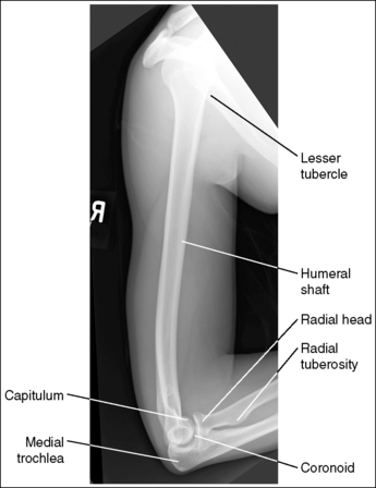

Scatter radiation is controlled. Image density is uniform across the humerus.
• If the patient's upper arm AP thickness measures less than 4 inches (10 cm), a grid is not required, but a grid is required if the patient's upper arm measures more than 4 inches (10 cm). When a grid is used, increase the penetration to above 60 kVp to penetrate the thicker humerus and provide an adequate scale of contrast. If the technique is manually set, increase the exposure (mAs) by the standard density conversion factor for the grid ratio used to compensate for the absorption of the scatter and primary radiation that occurs.
• Anode heel effect. To take advantage of the anode heel effect, position the thinner elbow (distal humerus) at the anode end of the tube and the thicker (proximal humerus) at the cathode end. Set an exposure (mAs) that will adequately demonstrate the midpoint of the humerus.
The humerus is in a lateral projection. The lesser tubercle is demonstrated in profile medially, and the humeral head and greater tubercle are superimposed. For a mediolateral projection, most of the radial head is demonstrated anterior to the coronoid process, the radial tuberosity is demonstrated in profile, and the capitulum is visualized proximal to the medial trochlea (see Figure 4-91). For a lateromedial projection, the radial head and coronoid process are superimposed, the radial tuberosity is not demonstrated in profile, and the capitulum is visible distal to the medial trochlea (see Figure 4-92).
• Two methods can be used to position the patient for a lateral humerus projection, mediolateral and lateromedial. The first method positions the patient's body in an upright PA projection, with the elbow flexed 90 degrees and the forearm and humerus internally rotated until an imaginary line connecting the humeral epicondyles is perpendicular to the IR; this is termed a mediolateral projection (Figure 4-93). Have the patient rotate the humerus internally while the body maintains a PA projection. Do not allow the patient to rotate the body toward the affected humerus instead. Such body obliquity would cause a decrease in density of the proximal humerus compared with the distal humerus (see Image 103), because the shoulder tissue would be superimposed over the proximal humerus. If body rotation cannot be avoided, an increase in exposure (mAs) is required to demonstrate the upper humerus adequately.
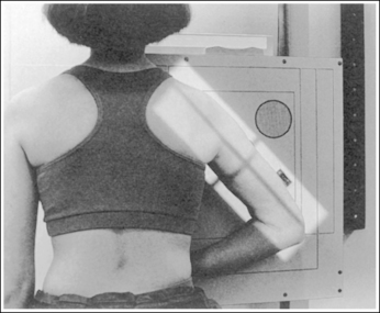
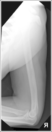
• The second method positions the patient's body in an AP projection. The hand is positioned against the patient's side, the elbow is slightly flexed, and the forearm and humerus are internally rotated until an imaginary line connecting the humeral epicondyles is perpendicular to the IR; this is termed a lateromedial projection (Figure 4-94). If the patient's forearm is positioned across the body in an attempt to flex the elbow 90 degrees and the distal humerus is not brought away from the IR enough to position the humeral epicondyles perpendicular to the IR (Figure 4-95), the image demonstrates the capitulum posterior to the medial trochlea, a distorted proximal forearm, and the lesser tubercle in partial profile (see Image 104). The difference in the anatomic relationship of the distal humerus between the mediolateral and lateromedial projections is a result of x-ray beam divergence. For a lateral humerus projection, the central ray is centered to the midhumeral shaft, which is located approximately 5 inches (13 cm) from the elbow joint. Because the elbow joint is placed so far away from the central ray, diverged x-ray beams are used to image the elbow joint. This causes the anatomic structures positioned farthest from the IR to be diverged more distally than the anatomic structures positioned closest to the IR. In the mediolateral projection, the medial trochlea is placed farther from the IR than the capitulum. Consequently, x-ray beam divergence will project the medial trochlea distal to the capitulum. In the lateromedial projection the capitulum is situated farther from the IR; therefore, the x-ray beam divergence will project it distally to the medial trochlea.
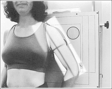
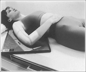
Figure 4-95 Patient positioned for lateromedial humerus projection with poor distal humerus alignment.
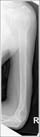
• Positioning for a humeral fracture. When a fracture of the humerus is suspected or a follow-up image is being taken to assess healing of a fracture, the patient's forearm or humerus should not be rotated to obtain a lateral position. Rotation of the forearm and humerus would increase the risk of radial nerve damage and displacement of the fracture fragments. Because the forearm should not be rotated for a trauma examination, a lateral image of the proximal and distal humerus must be obtained by positioning the patient differently.
• Distal humeral fracture. Obtain a lateral distal humerus projection by gently sliding an IR between the patient and the distal humerus. Adjust the IR until the epicondyles are positioned perpendicularly to the IR. Place a flat contact protecting shield between the patient and the IR to absorb any radiation that would penetrate the IR and expose the patient. Finally, center the central ray perpendicularly to the IR and distal humerus (Figure 4-96). This positioning should demonstrate a true lateral projection of the distal humerus with superimposition of the epicondyles and of the radial head and coronoid process (see Image 105).
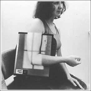
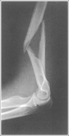
Image 105
• Proximal humeral fracture. A lateral projection can be achieved by positioning the patient in one of two ways. The first method is best done with the patient in an upright position, a position known as the scapular Y, PA axial projection. Begin by placing the patient in a PA upright projection with the humerus positioned as is, and then rotate the patient toward the affected humerus (approximately 45 degrees) until the scapular body is in a lateral position (Figure 4-97; see Image 106). Precise positioning and evaluating points for this image can be studied by referring to the discussion of the PA oblique (scapular Y) projection (see page 270).
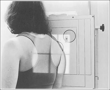
Figure 4-97 Proper positioning of a PA oblique (scapular Y) projection for a proximal humerus fracture.
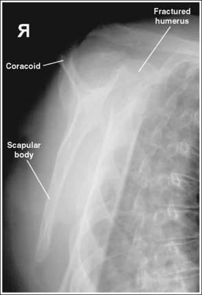
Image 106
The second method of obtaining a lateral projection of the proximal humerus can be accomplished with an upright or recumbent position. It is known as the transthoracic lateral position (Figure 4-98). The patient's body is placed in a lateral projection with the affected humerus resting against the grid IR, and the unaffected arm is raised above the patient's head. To prevent superimposition of the shoulders on the image, either (1) elevate the unaffected shoulder by tilting the upper midsagittal plane toward the IR and using a horizontal central ray, or (2) position the shoulders on the same transverse plane and angle the central ray 10 to 15 degrees cephalically.
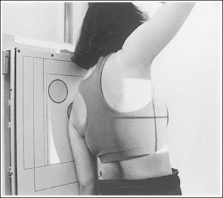
Figure 4-98 Proper positioning of a transthoracic lateral projection for a proximal humerus fracture.
For both projections, direct the central ray to the midthorax at the level of the affected shoulder. Use breathing technique to blur the vascular lung markings and axillary ribs. With this technique, a long exposure time (3 seconds) is used while the patient breathes shallowly (costal breathing) during the exposure. A transthoracic projection with accurate positioning should sharply demonstrate the affected proximal humerus halfway between the sternum and the thoracic vertebrae, without superimposition of the unaffected shoulder (see Image 107).
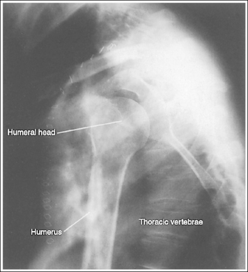
Image 107
The long axis of the humerus is aligned with the long axis of the collimated field.
• If the patient's humerus can remain aligned with the long axis of the IR while the elbow and shoulder joints are included on the IR, align the long axis of the collimated light field with the long axis of the humerus to allow for tight transverse collimation. For many adult humeral images, it may be necessary to position the humerus diagonally on the IR to include the elbow and shoulder joint. If using screen-film or digital radiography (DR) systems for this positioning, the collimator head or tube column should be turned or rotated to align the long axis of the collimated light field with the long axis of the humerus. If a grid is used, do not rotate the tube column or grid cutoff will result. This is not recommended with CR systems. If the collimator head or tube column cannot be adjusted for diagonal positioning, leave the transversely collimated field open enough to include the elbow and shoulder joint. With this setup the collimated field includes a large portion of the patient's thorax. Therefore the thorax is exposed to unnecessary radiation but can be protected by laying a flat contact shield across it. Remember to leave at least 3 inches (7.5 cm) of space between the humeral head and the shield to allow for magnification, so that the shoulder joint is not obscured by the shield.
The humeral midpoint is at the center of the exposure field. The shoulder and elbow joints, the proximal humerus and forearm, and the lateral humeral soft tissue are included within the collimated field.
• To place the humeral midpoint in the center of the image, palpate (1) the acromion angle (Figure 4-99) for a mediolateral projection or (2) the coracoid process for a lateromedial projection and the medial epicondyle. Position the central ray with the humeral midpoint at a level halfway between the two palpable landmarks. To include the elbow and shoulder joints on the image, the degree of radiation beam divergence used when imaging a long body part needs to be considered.

• IR length and positioning. Choose an IR that is long enough to allow at least 1 inch (2.5 cm) of IR to extend beyond each joint space; a 14- × 17-inch (35- × 44-cm) screen-film or computed radiography IR placed lengthwise should be adequate. On a patient with a long humerus, it may be necessary to position the humerus somewhat diagonally on the IR to obtain the needed IR length. For the CR system, it is not advisable to position the part diagonally unless the system is set to handle this alignment. Palpate the joints to ensure that the IR extends beyond them. The elbow is located approximately 0.75 inch (2 cm) distal to the medial epicondyles. The shoulder joint is located at the same level as the palpable coracoid and acromion angle.
• Central ray centering and collimation. Once the humerus is accurately positioned with the IR and the central ray is centered to the humeral midpoint, open the longitudinal collimated field until it extends 1 inch (2.5 cm) beyond the elbow and shoulder joint. If the collimation does not extend beyond both joints, adjust the centering point of the central ray until both the elbow and shoulder joint are included within the collimated field without demonstrating an excessive light field beyond them. Transverse collimation should be within 0.5 inch (1.25 cm) of the skin line laterally and to (1) the lateral scapular border for the mediolateral projection or (2) the coracoid for the lateromedial projection.
Lateral Humeral Projection Analysis
The density is lighter at the proximal humerus than at the distal humerus. The torso was not in a PA projection but was rotated toward the humerus, increasing the tissue thickness at the proximal humerus.
Analysis
The humerus is not in a lateral projection. The epicondyles are not superimposed, the capitulum is posterior to the medial trochlea, and the proximal forearm is distorted. The forearm was positioned across the patient's body and the distal humerus was not drawn away from the table to place the epicondyles perpendicular to the IR, as shown in Figure 4-95.
Correction
Position the patient as shown in Figure 4-94, with the distal humerus positioned adjacent to the IR, aligning the humeral epicondyles perpendicularly to the IR.
Analysis
This is a lateral distal humeral projection demonstrating a fractured distal humerus. The patient was accurately positioned.
Analysis
This is an AP oblique (scapular Y) shoulder projection demonstrating a fractured proximal humerus. The image demonstrates accurate positioning. The scapular body is in a true lateral position. The scapular body, acromion, and coracoid form a Y, with the scapular body as the leg and the acromion and coracoid as the arms.