Upper Extremity
Finger: Posteroanterior Projection
Finger: Posteroanterior Oblique Projection
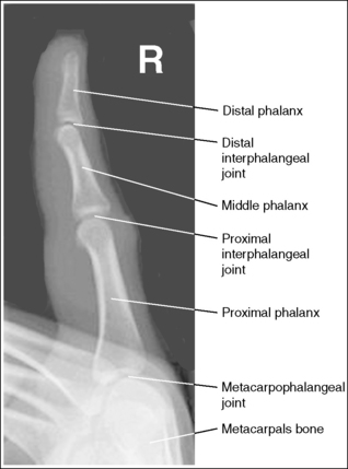
Lateral Finger Projection Analysis
Thumb: Anteroposterior Projection
Thumb: Posteroanterior Oblique Projection
Hand: Posteroanterior Projection
Hand: Posteroanterior Oblique Projection (External Rotation)
Hand: “Fan” Lateral Projection (Lateromedial)
Wrist: Posteroanterior Projection
Wrist: Posteroanterior Oblique Projection (External Rotation)
Wrist: Lateral Projection (Lateromedial)
Wrist: Ulnar Deviation, Posteroanterior Axial Projection (Scaphoid)
Wrist Carpal Canal: Tangential, Inferosuperior Projection
Forearm: Anteroposterior Projection
Forearm: Lateral Projection (Lateromedial)
Elbow: Anteroposterior Projection
Elbow: Anteroposterior Oblique Projections (Internal and External Rotation)
Elbow: Lateral Projection (Lateromedial)
Elbow: Axiolateral Projection (Coyle Method)
• Identify the required anatomy on upper extremity projections.
• Describe how to properly position the patient, image receptor (IR), and central ray on upper extremity projections.
• List the image analysis requirements for upper extremity projections with accurate positioning.
• State how to reposition the patient properly when upper extremity projections with poor positioning are produced.
• State the kilovoltage that is routinely used for upper extremity projections, and describe which anatomic structures will be visible when the correct technique factors are used.
• Explain how a joint space is aligned with the central ray and IR to be demonstrated as an open space on an image.
• List the soft tissue structures that are of interest and should be demonstrated on upper extremity projections. State where they are located and describe why their visualization is important.
• Explain how wrist and elbow rotations affect the placement of the radial and ulnar styloids, and radial turberosity on upper extremity projections.
• Describe the slant of the distal radial articulating surface.
• Discuss how a patient with large, muscular, or thick proximal forearms should be positioned for good posteroanterior (PA) and lateral wrist projections to be obtained.
• State the carpal bone changes that occur when the wrist is extended, flexed, or ulnar- and radial-deviated in hand and wrist projections.
• Discuss how the degree of central ray angulation needs to be adjusted for the PA ulnar-deviated scaphoid position if a proximal or distal scaphoid fracture is in question.
• Describe what effect the anode heel effect has on forearm and humeral projections and discuss how to position the arm to take advantage of the anode heel effect.
• Explain how to position the patient to ensure that appropriate joints are included on forearm and humerus projections.
• State why the patient's humerus is never rotated if a humeral fracture is suspected.
• Explain when a grid is needed for humeral images and how the technique factors are adjusted when a grid is added.
The following image analysis criteria are used for all upper extremity images and should be considered when completing the analysis for each upper extremity projection presented in this chapter (Box 4-1).
An optimal kilovoltage peak (kVp) technique (Table 4-1) sufficiently penetrates the bony and soft tissue structures of the upper extremity and provides a contrast scale necessary to visualize the bony details. To obtain optimal density, set a manual milliampere-seconds (mAs) level based on the part thickness.
TABLE 4-1
Upper Extremity Technical Data
| Projection | kVp | SID |
| Finger | 50–60 | 40–48 inches (100–120 cm) |
| Thumb | 50–60 | 40–48 inches (100–120 cm) |
| PA hand | 50–60 | 40–48 inches (100–120 cm) |
| PA oblique, hand | 50–60 | 40–48 inches (100–120 cm) |
| Lateral hand | 50–60 | 40–48 inches (100–120 cm) |
| Wrist | 50–60 | 40–48 inches (100–120 cm) |
| Forearm | 50–60 | 40–48 inches (100–120 cm) |
| Elbow | 50–60 | 40–48 inches (100–120 cm) |
| Humerus | 50–60 | 40–48 inches (100–120 cm) |
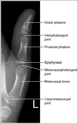
FINGER: POSTEROANTERIOR PROJECTION
See Figure 4-1 and Box 4-2.
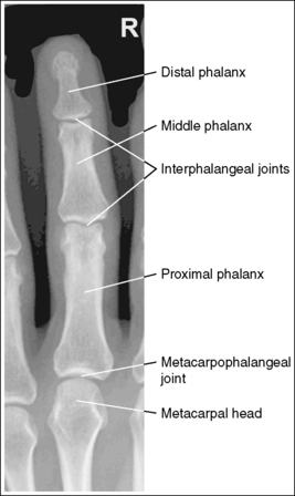
The finger demonstrates a PA projection. The soft tissue width and midpoint concavity are the same on both sides of the phalanges.
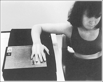
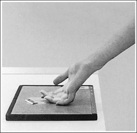
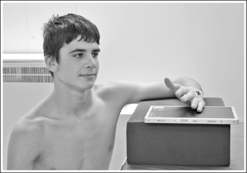
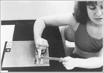
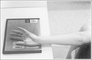
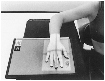
• Finger rotation is controlled by the amount of palm pronation. A PA projection is accomplished when the palm is positioned flat against the IR (Figure 4-2).
• Detecting finger rotation. Because the thumb prevents the hand from rotating laterally, medial rotation is the most common rotation error. Take a few minutes to study a finger skeleton, and note how the midpoints of the phalanges have equal side concavity when it is placed in a PA projection. Also, note that the anterior surface is concave, whereas the posterior surface is slightly convex. As the skeleton is rotated internally or externally, the amount of concavity increases on the side toward which the anterior surface is rotated, whereas the side toward which the posterior surface rotates demonstrates less concavity. The same observations can be made about the soft tissue that surrounds the phalanges. More soft tissue thickness is present on the anterior (palmar) hand surface than on the posterior surface, so the side demonstrating the greatest soft tissue width on an image is the side toward which the anterior surface was rotated. Look for this midpoint concavity and soft tissue width variation to indicate rotation on a PA finger projection (see Image 1). Note on a hand skeleton that the second metacarpal is the longest of the finger digits and that the length decreases with each adjacent metacarpal. This information can be used to determine whether the patient's finger was internally or externally rotated for a mispositioned PA finger image. If the finger was externally rotated, the aspect of the phalanges demonstrating the greater midpoint concavity faces the thumb or longer metacarpal (see Image 1). If the finger was internally rotated, the aspect of the phalanges demonstrating the greater midpoint concavity faces the shorter metacarpal.

Image 1
No soft tissue overlap from adjacent digits is present.
• Spreading the fingers slightly prevents soft tissue overlapping from adjacent fingers. It is difficult to evaluate the soft tissue of an affected finger when superimposition of other soft tissue is present.
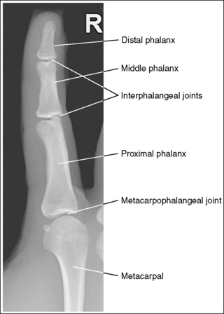
The interphalangeal (IP) and metacarpophalangeal (MP) joints are demonstrated as open spaces, and the phalanges are not foreshortened.
• Open IP and MP joint spaces and unforeshortened phalanges are demonstrated when the finger is fully extended and the central ray is perpendicular and centered to the proximal IP (PIP) joint. This finger positioning and central ray placement align the joint spaces parallel with the central ray and perpendicular to the IR, as shown in Figure 4-3, resulting in open joint spaces. It also prevents foreshortening of the phalanges, because their long axes are aligned parallel with the IR and perpendicular to the central ray. The alignment of the central ray and IR with the joint spaces and phalanges changes when the finger is flexed. In Figure 4-4, note how finger flexion causes the phalanges to foreshorten and be superimposed on the joint spaces (see Image 2).
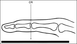
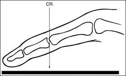
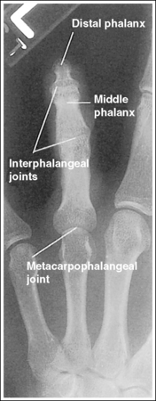
Image 2
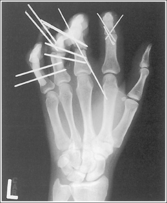
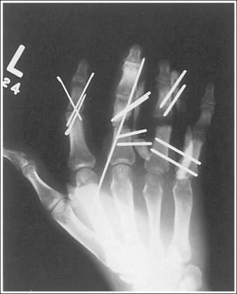
• Positioning the unextendable finger. If the patient is unable to extend the finger, it may be necessary to use an anteroposterior (AP) projection to demonstrate open IP and MP joint spaces and to visualize the phalanges of greatest interest without foreshortening. In this case, carefully evaluate the requisition to determine the phalanx and joint space of interest. Then, supinate the patient's hand into an AP projection, elevating the proximal metacarpals until the phalanx of interest is parallel with the IR and the joint space of interest is perpendicular to the IR (Figure 4-5). Figures 4-6 and 4-7 demonstrate how patient positioning with respect to the central ray determines the anatomy that is visible. For Figure 4-6, the patient was imaged in a PA projection with fingers flexed. For Figure 4-7, the same patient was imaged in an AP projection with the proximal metacarpals elevated to place the affected proximal phalanges parallel with the IR. Note the difference in demonstration of the joint spaces and proximal phalanx fractures.
The PIP joint is at the center of the exposure field. The distal, middle, and proximal phalanges and half of the metacarpal are included within the collimated field.
• Direct a perpendicular central ray to the PIP joint to place the joint in the center of the image. Open the longitudinal collimation to include the distal phalanx and the distal half of the metacarpal. Transverse collimation should be within 0.5 inch (1.25 cm) of the finger skin line.
• One third of an 8- × 10-inch (18- × 24-cm) detailed screen-film or computed radiography IR placed crosswise should be adequate to include all the required anatomic structures. Digital imaging requires tight collimation, lead masking, and no overlap of individual exposures to produce optimal images.
• Some facilities request that an unaffected adjacent digit be included on the image for comparison purposes. For a finger being imaged for the first time, some facilities want the entire metacarpal to be visualized on the image.
Posteroanterior Finger Projection Analysis
The soft tissue width and the concavity of the phalangeal midshafts on either side of the phalanx are not equal; the finger was rotated for the image. Because the side of the phalanges with the greater concavity and soft tissue width is facing the thumb, the finger was rotated externally for the image.
Correction
Place the finger in a PA projection by rotating the finger slightly internally. The hand should be flat against the IR.
Analysis
The IP and MP joints are closed, and the distal and middle phalanges are foreshortened; the patient's finger was flexed.
Correction
Extend the patient's finger, and place the palm flat against the IR. If the patient is unable to extend the finger, image it in an AP projection, elevating the proximal metacarpals until the affected phalanx is parallel with the IR or the affected joint space is perpendicular to the IR (see Figure 4-5).
FINGER: POSTEROANTERIOR OBLIQUE PROJECTION
See Figure 4-8 and Box 4-3.
The digit has been placed in a 45-degree PA oblique projection. Twice as much soft tissue width is demonstrated on one side of the digit as on the other side, and more concavity is demonstrated on one aspect of the phalangeal midshafts than on the other.
• A PA oblique finger is accomplished by rotating the affected finger 45 degrees from the PA projection (Figure 4-9). It is most common and comfortable for a patient to rotate the finger and hand externally to obtain a PA oblique finger projection, although internal rotation may be used when the second digit is imaged, to prevent a long object–image receptor distance (OID).
• Assessing accuracy of PA oblique projection. Study the amount of phalangeal midshaft concavity and soft tissue width demonstrated on PA oblique finger projections to verify the accuracy of rotation and to determine the proper repositioning movement needed when an oblique digit image shows too much or too little obliquity. A 45-degree oblique finger image demonstrates more phalangeal midshaft concavity and soft tissue width on the side positioned away from the IR. Use the soft tissue width to assess the degree of digital obliquity. If twice as much soft tissue width is present on one side of the digit as on the other, a 45-degree PA oblique projection has been obtained. If the phalangeal midshaft concavity and soft tissue width on both sides of the finger are more nearly equal, the finger was not rotated enough for the projection (see Image 3). If the soft tissue width on one side of the digit is more than twice as much as that on the other, and when one aspect of the phalangeal midshaft is concave but the other aspect is convex, the angle of obliquity was more than 45 degrees (see Image 4).
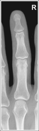
Image 3
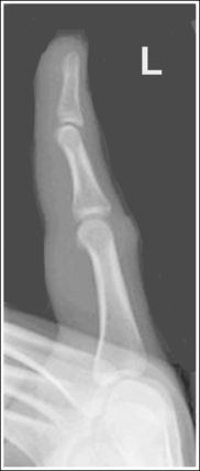
Image 4
No soft tissue overlap from adjacent digits is present.
• Slightly spread the patient's fingers to prevent overlapping of the adjacent finger's soft tissue onto that of affected finger. Superimposition of these soft tissues makes it difficult to evaluate the soft tissue of the affected finger (see Image 5).
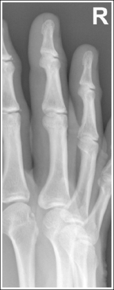
Image 5
The IP and MP joints are visualized as open spaces, and the phalanges are not foreshortened.
• The IP and MP joint spaces are open and the phalanges are not foreshortened if the finger is fully extended and positioned parallel with the IR and perpendicular to the central ray. When the hand and fingers are positioned obliquely, some of the fingers are no longer placed against the IR but are positioned at varying OIDs. In this position the distal phalanges naturally tilt toward the IR. To keep the affected finger parallel with the IR and to maintain open joint spaces, it may be necessary to place an immobilization device beneath the distal phalanx. This is especially true when the second and third digits are imaged because they are at the greatest OID. It is also necessary to center a perpendicular central ray to the PIP joint to maintain open joint spaces. Failure to position the affected finger parallel with the IR and perpendicular to the central ray foreshortens the phalanges and closes the joint spaces (see Image 6).
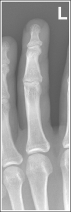
Image 6
The PIP joint is at the center of the exposure field. The distal, middle, and proximal phalanges and half of the metacarpal of the affected digit are included within the collimated field.
• Direct a perpendicular central ray to the PIP joint to place it in the center of the image. Open the longitudinal collimation to include the distal phalanx and the distal half of the metacarpal. Transversely collimate to within 0.5 inch (1.25 cm) of the finger skin line.
• One third of an 8- × 10-inch (18- × 24-cm) detailed screen-film or computed radiography IR placed crosswise should be adequate to include all the required anatomic structures.
• Some facilities require an unaffected adjacent digit to be included on the image for comparison purposes. Also, for a finger being imaged for the first time, some facilities want the entire metacarpal to be visualized on the image.
PA Oblique Finger Projection Analysis
On both sides of the phalanx the soft tissue width and midshaft concavity are almost equal; the patient's finger was positioned at less than 45 degrees of obliquity for the image.
Analysis
More than twice as much soft tissue width is present on one side of the phalanges as on the other. One aspect of the midshafts of the phalanges is concave, and the other aspect is slightly convex. Obliquity was more than 45 degrees for this image.
Analysis
Soft tissue from an adjacent finger is superimposed over the affected finger's soft tissue; the fingers were not spread apart.
Correction
Spread the fingers until the adjacent fingers are positioned away from the affected finger.
Analysis
The IP joint spaces are closed, and the distal and middle phalanges are foreshortened; the finger was not positioned parallel with the IR.
Correction
Position the finger parallel with the IR. It may be necessary to position an immobilization device beneath the distal phalanx to maintain accurate finger positioning. If the distal phalanx is of interest and the patient is unable to extend the finger, image it in an AP oblique projection, elevating the proximal metacarpals until the affected phalanx is aligned parallel with the IR and rotated 45 degrees.
FINGER: LATERAL PROJECTION
See Figure 4-10 and Box 4-4.
The digit of interest is in a lateral projection. The anterior aspect of the middle and proximal phalanges demonstrates midshaft concavity, and the posterior aspects of the phalanges show slight convexity.
• A lateral finger projection is accomplished by rotating the affected finger 90 degrees from the PA projection (Figure 4-11). Whether the hand is rotated internally or externally to obtain this goal depends on which direction will bring the finger closer to the IR. Typically, when the second and third fingers are imaged, the hand is rotated internally and, when the fourth and fifth fingers are imaged, the hand is rotated externally.
• Distinguishing lateral projection from rotated projection. To understand the difference between a truly lateral digit projection and a lateral projection that is rotated, study a finger skeleton in lateral and PA and AP oblique projections. Note how the midshaft concavity of the middle and proximal phalanges varies as the digit is rotated. In a lateral projection, the anterior aspect of these phalanges is concave, but the posterior aspect demonstrates slight convexity. In PA and AP oblique projections, both sides of the middle and proximal phalangeal midshafts demonstrate concavity, but the side toward which the anterior surface is rotated demonstrates a greater degree of concavity than the side toward which the posterior surface is rotated. The soft tissue width at either side of the phalanx also changes in the lateral and PA and AP oblique projections. More soft tissue is present on the side of the phalanges toward which the anterior surface is rotated (see Image 7).
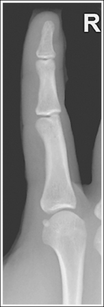
Image 7
No soft tissue overlap from adjacent digits is present.
• Flex the unaffected fingers into a tight fist, allowing the finger of interest to remain extended. To visualize the proximal phalanx, it may be necessary to extend the affected finger with an immobilization device or to tape the unaffected fingers away from the affected finger. If the unaffected fingers are not drawn away from the proximal phalanx of the affected finger, they will be superimposed on the area, preventing adequate visualization (see Image 8). An immobilization device should not be used to extend the finger if a fracture is suspected and the device causes stress to the fractured area (see Image 9).
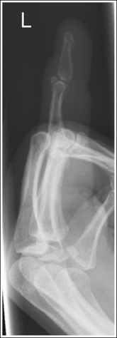
Image 8
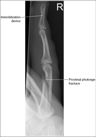
Image 9
The IP joints are visible as open spaces, and the phalanges are not foreshortened.
• The IP joints are open, and the phalanges are demonstrated without foreshortening as long as the finger was positioned parallel with the IR and the central ray was perpendicular to and centered with the PIP joint.
• When the third and fourth digits are imaged, they are positioned at a greater OID than the second and fifth digits. To keep the third and fourth digits parallel with the IR, it may be necessary to place an immobilization device beneath their distal phalanges. When a finger is not positioned parallel with the IR and perpendicular to the central ray, the IP joint spaces are closed and the phalanges are foreshortened.
The PIP joint is at the center of the exposure field. The distal, middle, and proximal phalanges and the metacarpal head of the affected digit are included within the collimated field.
• Center a perpendicular central ray to the PIP joint to place it in the center of the image. Open the longitudinal collimation to include the distal phalanx and the metacarpal head. Transversely collimate to within 0.5 inch (1.25 cm) of the finger skin line.
• One third of an 8- × 10-inch (18- × 24-cm) detailed screen-film or computed radiography IR placed crosswise should be adequate to include all the required anatomic structures.
Lateral Finger Projection Analysis
Analysis
Concavity is demonstrated on both sides of the middle and proximal phalangeal midshafts, indicating that the finger was not adequately rotated for this image.
Analysis
The unaffected fingers were not flexed enough to prevent soft tissue or bony superimposition of the affected digit's proximal phalanx.
Correction
Tightly flex the unaffected fingers away from the affected finger. Hyperextending the affected finger with an immobilization prop may also help increase demonstration of the proximal phalanx if a fracture of this area is not suspected.
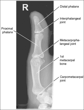
THUMB: ANTEROPOSTERIOR PROJECTION
See Figures 4-12 and 4-13 and Box 4-5.
The first digit demonstrates an AP projection. The concavity on both sides of the phalangeal and metacarpal midshafts is equal, as is soft tissue width on both sides of the phalanges.
• An AP projection is accomplished by internally rotating the patient's hand until the thumb is positioned in an AP projection (Figure 4-14). The thumbnail can be used as a reference to determine when the thumb is truly placed in an AP projection. The nail should be positioned directly against the IR and should not be visible on either side of the thumb. A nonrotated AP thumb projection demonstrates equal concavity on both sides of the phalangeal and metacarpal midshafts, as well as equal soft tissue widths on both sides of the phalanges.
• Detecting thumb rotation.When the thumb is rotated away from an AP projection, the amount of midshaft concavity increases on the side of the thumb toward which the anterior surface rotates and decreases on the side toward which the posterior surface rotates. The same observation can be made about the soft tissue surrounding the phalanges when the thumb is rotated. More soft tissue width is evident on the side toward which the anterior surface is rotated, and less soft tissue width is seen on the side toward which the posterior surface is rotated (see Image 10).
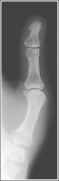
Image 10
The long axis of the thumb is aligned with the long axis of the collimated field.
• Aligning the long axis of the thumb with the long axis of the collimator's longitudinal light line enables you to collimate tightly without clipping the distal phalanx or proximal metacarpal (see Image 11).
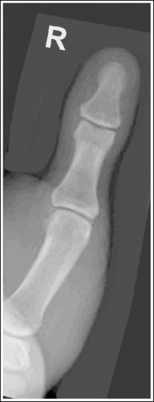
Image 11
The IP, MP, and carpometacarpal (CM) joints are visible as open joint spaces, and the phalanges are not foreshortened.
• The IP, MP, and CM joint spaces are open, and the phalanges are demonstrated without foreshortening as long as the thumb is positioned flat against and placed parallel with the IR and the central ray was perpendicular to and centered with the MP joint space. This positioning aligns the joint spaces parallel with the central ray and perpendicular to the IR and positions the long axes of the phalanges perpendicular to the central ray and parallel with the IR. These relationships change when the thumb is flexed or posteriorly extended (hitchhiker's thumb) for the image. Thumb flexion and extension foreshorten the phalanges and superimpose them over the joint spaces (see Image 12).
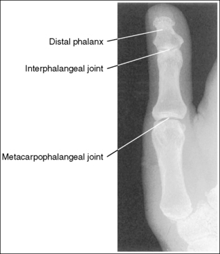
Image 12
Superimposition of the medial palm soft tissue over the proximal first metacarpal and the CM joint is minimal.
• Minimal soft tissue overlap occurs when the medial palm surface is drawn away from the thumb. It may be necessary to use the patient's other hand as an immobilization device to maintain good positioning of the medial palmar surface. If the medial surface of the palm is not drawn away from the thumb, the soft tissue and possibly the fourth and fifth metacarpals obscure the proximal first metacarpal and CM joint (see Image 13).
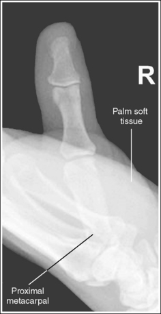
Image 13
• Evaluating a PA thumb projection. The principles of AP thumb projection analysis can be used to evaluate a PA thumb projection (Figure 4-15), with the following modifications. First, the medial palm soft tissue does not overlap the proximal first metacarpal and CM joint. Second, on a PA projection, the CM joint is closed.
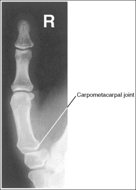
The MP joint is at the center of the exposure field. The distal and proximal phalanges, the metacarpal, and the CM joint are included within the collimated field.
• Center a perpendicular central ray to the MP joint, which is located where the palm's interconnecting skin attaches to the thumb, to place it in the center of the image. Open the longitudinal collimation to include the distal phalanx and CM joint. Transversely collimate to within 0.5 inch (1.25 cm) of the thumb skin line.
• One third of an 8- × 10-inch (18- × 24-cm) detailed screen-film or computed radiography IR placed crosswise should be adequate to include all the required anatomic structures. Digital imaging requires tight collimation, lead masking, and no overlap of individual exposures to produce optimal images.
Anteroposterior Thumb Projection Analysis
Analysis
The soft tissue width and the concavity of the phalangeal and metacarpal midshafts are not the same on both sides. The side next to the fingers demonstrates more concavity. The hand was internally rotated too far, demonstrating the thumb in an AP oblique projection.
Correction
Decrease the internal hand rotation until the thumb is in an AP projection. The thumbnail should be resting against the IR and should not be visible on either side of the thumb.
Analysis
The long axis of the thumb is not aligned with the long axis of the collimated field. Note that the proximal metacarpal and the CM joint are clipped.
Analysis
The distal phalanx is foreshortened, and the IP joint space is closed. The MP joint was elevated off the IR and the distal thumb was posteriorly extended (hitchhiker's thumb).
Analysis
The fifth metacarpal and the medial palm soft tissue are superimposed over the proximal first metacarpal and CM joint. The medial metacarpal and palmar surface have not been drawn away from the thumb.
Correction
Using the patient's other hand or another immobilization device, draw the medial side of the hand and palmar surface away from the thumb. Make sure that the thumb does not rotate away from an AP projection with this movement and that the patient's opposite hand is not included in the exposure field.
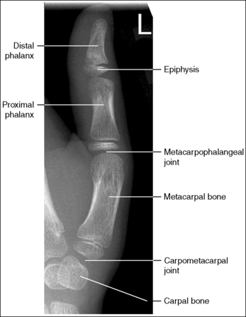
THUMB: LATERAL PROJECTION
See Figures 4-16 and 4-17 and Box 4-6.
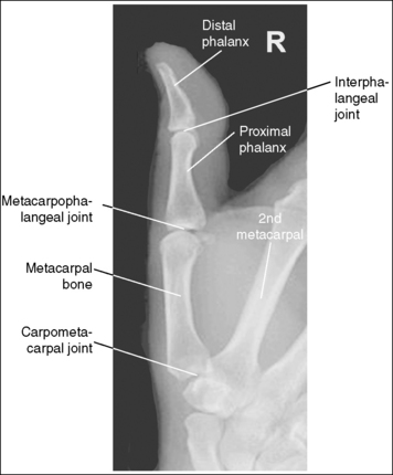
The thumb demonstrates a lateral projection. The anterior aspect of the proximal phalanx and metacarpal demonstrates midshaft concavity, and the posterior aspect of the proximal phalanx and metacarpal demonstrates slight convexity.
• To accomplish a lateral thumb projection, place the patient's hand flat against the IR; then flex the hand and fingers only until the thumb naturally rolls into a lateral projection (Figure 4-18). Overflexion causes superimposition of the second and third proximal metacarpals onto the proximal first metacarpal, obscuring it (see Image 14). When the hand and fingers are accurately flexed and the thumb is in a lateral projection, the midshaft of the proximal phalanx and metacarpal demonstrates concavity on their anterior aspects and convexity on their posterior aspects. If the patient's hand is not rotated enough to place the thumb in a lateral projection, the posterior aspects of these midshafts show some degree of concavity (see Image 15).
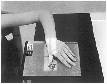
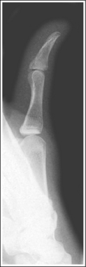
Image 14
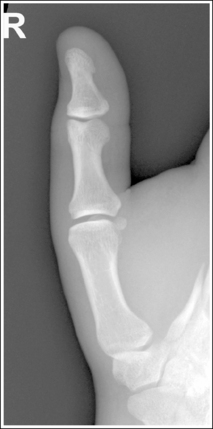
Image 15
The IP, MP, and CM joints are visible as open spaces, and the phalanges are not foreshortened.
• The IP, MP, and CM joints are open and the phalanges are visible without foreshortening if the entire thumb rests against and is positioned parallel with the IR and a perpendicular central ray is centered to the MP joint.
The proximal first metacarpal is only slightly superimposed by the proximal second metacarpal.
• Whenever possible, the anatomic part of interest should be demonstrated without superimposition. For a lateral thumb projection, the proximal metacarpal can be demonstrated with only a very small amount of superimposition if the thumb is abducted away from the palm. Failure to abduct the thumb results in a significant amount of first and second proximal metacarpal overlap and obstruction of the CM joint (see Image 16).
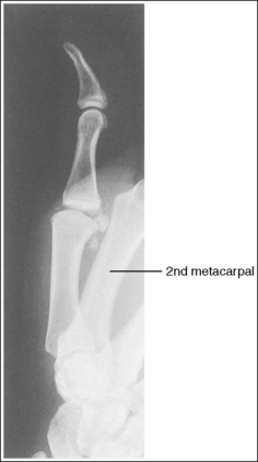
Image 16
The first MP joint is at the center of the exposure field. The distal and proximal phalanges, the metacarpal, and the CM joint are included within the collimated field.
• Center a perpendicular central ray to the MP joint, which is located where the palm's interconnecting skin attaches to the thumb, to place it in the center of the image. Open the longitudinal collimation to include the distal phalanx and CM joint. Transversely collimate to within 0.5 inch (1.25 cm) of the thumb skin line.
• One third of an 8- × 10-inch (18- × 24-cm) detailed screen-film or computed radiography IR placed crosswise should be adequate to include all the required anatomic structures. Digital imaging requires tight collimation, lead masking, and no overlap of individual exposures to produce optimal images.
Lateral Thumb Projection Analysis
The second and third proximal metacarpals are superimposed over the first proximal metacarpal. The hand was overflexed.
Correction
Abduct the thumb away from the hand, and decrease the amount of hand flexion while maintaining a lateral thumb projection.
Analysis
The thumb is not in a lateral projection. The posterior aspect of the proximal phalanx and metacarpal midshafts demonstrates concavity, indicating that the hand was not adequately flexed.
THUMB: POSTEROANTERIOR OBLIQUE PROJECTION
See Figures 4-19 and 4-20 and Box 4-7.
The thumb is in a 45-degree PA oblique projection. Twice as much soft tissue and more phalangeal and metacarpal midshaft concavity are present on the side of the thumb next to the fingers as on the other side.
• When the hand is extended and the palmar surface is placed flat against the IR, the thumb is rotated into a 45-degree PA oblique projection (Figure 4-21). In this position, more midshaft concavity is present on one side of the phalanges and metacarpal than on the other side. If the hand is not placed flat against the IR, the thumb rolls toward a lateral projection. The more flexed the fingers, the closer the thumb is to a lateral projection. Such positioning can be identified on an image by noting the concavity of the anterior aspect and the convexity of the posterior aspect of the proximal phalanx and metacarpal (see Image 17).
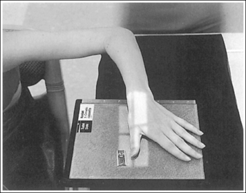
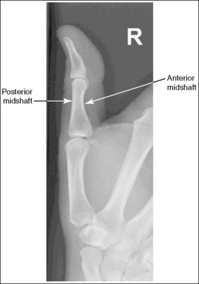
Image 17
The long axis of the thumb is aligned with the long axis of the collimated field.
• Aligning the long axis of the thumb with the long axis of the collimation light field enables you to collimate tightly without clipping the distal phalanx or proximal metacarpal (see Image 18).
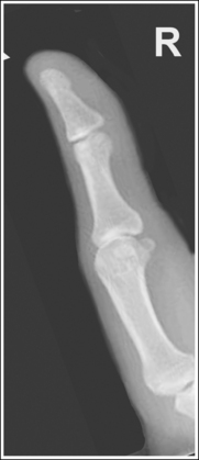
Image 18
The IP, MP, and CM joints are visible as open joint spaces, and the phalanges are not foreshortened.
• The IP, MP, and CM joint spaces are open and the metacarpal and phalanges are visible without foreshortening when the first proximal metacarpal palmar surface remains flat against the IR. If the hand is medially rotated, the palmar surface is lifted off the IR, causing the thumb to tilt downward. The downward tilt closes the IP and MP joint spaces and foreshortens the phalanges (see Image 19).
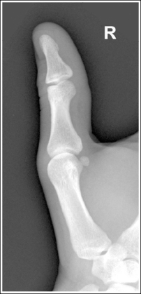
Image 19
The first MP joint is at the center of the exposure field. The distal and proximal phalanges, metacarpal, and CM joint are included within the collimated field.
• Center a perpendicular central ray to the MP joint, which is located where the palmar interconnecting skin attaches to the thumb, to place it in the center of the image. Open the longitudinal collimation to include the distal phalanx and CM joint. Transversely collimate to within 0.5 inch (1.25 cm) of the thumb skin line.
• One third of an 8- × 10-inch (18- × 24-cm) detailed screen-film or computed radiography IR placed crosswise should be adequate to include all the required anatomic structures.
PA Oblique Thumb Projection Analysis
The midshafts of the proximal phalanx and metacarpal demonstrate slight convexity on their posterior surfaces and concavity on their anterior surfaces. The thumb was positioned at more than 45 degrees of obliquity. The patient's palm was not placed flat against the IR.
Analysis
The long axis of the thumb is not aligned with the long axis of the collimated field. Note that the proximal metacarpal and the CM joint are partially clipped.
HAND: POSTEROANTERIOR PROJECTION
See Figure 4-22 and Box 4-8.
The digits and metacarpals demonstrate a PA projection. The soft tissue outlines of the second through fifth phalanges are uniform, the distance between the metacarpal heads is equal, and the same midshaft concavity is demonstrated on both sides of the phalanges and metacarpals of the second through fifth digits.
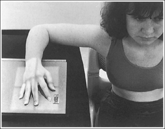
• A PA projection of the hand is obtained when the patient fully extends the hand and rests the palmar surface flat against the IR (Figure 4-23).
• PA versus external oblique hand position. If the hand is not fully extended but is slightly flexed, it often relaxes into an external PA oblique projection when it is resting against the IR. A PA oblique hand projection is signified by slight superimposition of the third through fifth metacarpal heads and unequal soft tissue thickness and midshaft concavity on the sides of the phalanges. The metacarpals also show unequal midshaft concavity and spacing (see Image 20). Abducting the patient's arm and placing the forearm and humerus on the same horizontal plane, with the elbow flexed 90 degrees, assists in preventing an externally rotated PA oblique projection and will best demonstrate the wrist. This is important if a wrist condition is causing radiation hand pain. When the patient has been positioned in this manner, the ulnar styloid appears in profile on the image. Internal rotation of the hand is seldom a problem, because the thumb prevents this movement.
Image 20
No soft tissue overlap of adjacent digits is present.
The IP, MP, and CM joints are visible as open spaces, and the phalanges and metacarpals are not foreshortened. The thumb is demonstrated in a 45-degree PA oblique projection.
• When the hand and fingers are fully extended and a perpendicular central ray is centered to the third MP joint space, the IP, MP, and CM joints are demonstrated as open spaces and the phalanges and metacarpals are seen without foreshortening on the PA hand projection.
• Flexion of the hand causes poor alignment of the phalanges, metacarpals, and IP and CM joint spaces with the IR and central ray, resulting in closed joint spaces and foreshortening of the phalanges and metacarpals (see Image 21). The position of the first digit also changes when the image is taken with the hand flexed, because flexion rotates the first digit into a lateral projection.
Image 21
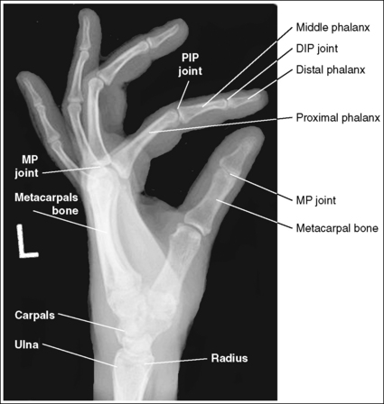
The third MP joint is at the center of the exposure field. The distal, middle, and proximal phalanges, the metacarpals, the carpals, and approximately 1 inch (2.5 cm) of the distal radius and ulna are included within the collimated field.
• Center a perpendicular central ray to the third MP joint to place it in the center of the collimated light field. This MP joint is situated just slightly distal to the head of the third metacarpal. Once the central ray is centered, open the longitudinal collimation to include the distal phalanx and 1 inch (2.5 cm) of the distal forearm. Transversely collimate to within 0.5 inch (1.25 cm) of the first and fifth finger's skin line.
• Either half of a 10- × 12-inch (24- × 30-cm) detailed screen-film IR placed crosswise or a single 8- × 10-inch (18- × 24-cm) digital IR placed lengthwise should be adequate to include all the required anatomic structures.
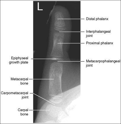
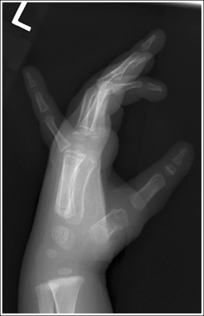
• Pediatric bone age assessment. A bone age image is obtained to assess the skeletal versus the chronologic age of a child. Because bones develop in an orderly pattern, skeletal age may be assessed from infancy through adolescence. Illness, metabolic or endocrine dysfunction, and taking certain types of medications and therapies are all reasons why a pediatric patient's skeletal and chronologic age may not correspond. A left PA hand and wrist projection is typically the image of choice because bony developmental changes are readily visible and easily evaluated. For skeletal age to be evaluated, the phalanges, metacarpals, carpals, and distal radius and ulna must be included in their entirety (see Figure 1-130).
Posteroanterior Hand Projection Analysis
The hand was externally rotated, as indicated by the superimposition of the third and fourth metacarpal heads, the unequal midshaft concavity on either side of the phalanges and metacarpals, and the uneven spacing of the metacarpal heads. The tip of the second and third fingers has been collimated off, and less than 1 inch (2.5 cm) of the distal radius and ulna is included.
Correction
Internally rotate the hand until the palm and fingers are placed flat against the IR, and open the longitudinally collimated field to include the second and third fingertips and 1 inch (2.5 cm) of the distal radius and ulna.
HAND: POSTEROANTERIOR OBLIQUE PROJECTION (EXTERNAL ROTATION)
See Figure 4-24 and Box 4-9.
The hand has been externally rotated 45 degrees. Each of the second through fifth metacarpal midshafts demonstrate more concavity on one side than on the other and have varying amounts of space between them. The first and second metacarpal heads are not superimposed, the third through fifth metacarpal heads are slightly superimposed, and a slight space is present between the fourth and fifth metacarpal midshafts.
• To accomplish a PA oblique hand projection, begin with the hand in a PA projection. Then, externally rotate the hand until it forms a 45-degree angle with the IR (Figure 4-25). To confirm the 45-degree angle, it is best to view the hand and not the wrist. The wrist will demonstrate more than 45 degrees of obliquity when the hand is in a 45-degree oblique projection, so using the wrist can result in a miscalculation of the amount of obliquity. This is especially true if the humerus and forearm have not been placed on the same horizontal plane. When the patient has been positioned with the arm on the same horizontal plane, the ulnar styloid is demonstrated in profile medially on the image. A radiolucent immobilization device can be used to help maintain this position.
• Verifying PA oblique hand projection. A 45-degree PA oblique hand projection can be recognized by the amount of metacarpal midshaft and metacarpal head superimposition. If the hand has not been rotated enough, the metacarpal relationship is similar to that demonstrated on a PA projection of the hand: The midshafts of the metacarpals are almost evenly spaced, and the metacarpal heads are not superimposed (see Image 22). On a 45-degree PA oblique hand projection, a space should be maintained between the fourth and fifth metacarpal midshafts. If the hand is rotated more than 45 degrees, this space is obscured and the fourth and fifth metacarpals demonstrate some degree of superimposition (see Image 23).
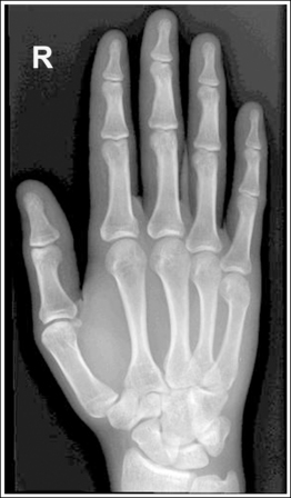
Image 22
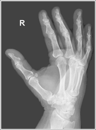
Image 23
No soft tissue overlap of adjacent digits is present.
• Fingers should be spread slightly to prevent soft tissue overlapping (Images 24 and 25).
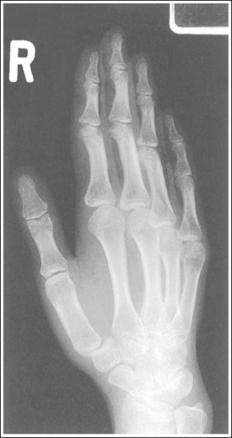
Image 24
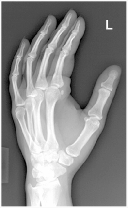
Image 25
The IP and MP joints are visible as open spaces, and the phalanges are demonstrated without foreshortening. The thumb's position may vary from a lateral to a PA oblique projection.
• The IP and MP joint spaces are open and the phalanges are not foreshortened when the hand and fingers are fully extended and aligned parallel with the IR. An immobilization device should be used to help the patient maintain this positioning.
• Disadvantages of using fingers as prop. A common positioning error in PA oblique hand projection is to use the patient's fingers instead of an immobilization device to maintain the oblique position. For this positioning, the fingers are flexed until the fingertips touch the IR to prop the hand (Figure 4-26). Such positioning closes the IP joint spaces and foreshortens the phalanges (Images 23 and 25).
The third MP joint is at the center of the exposure field. The distal, middle, and proximal phalanges, the metacarpals, the carpals, and approximately 1 inch (2.5 cm) of the distal radius and ulna are included within the collimated field.
• Center a perpendicular central ray to the third MP joint to place it in the center of the collimated light field. The MP joint is situated just slightly distal to the head of the third metacarpal. Once the central ray is centered, open the longitudinal collimation to include the distal phalanges and the distal forearm. Transversely collimate to within 0.5 inch (1.25 cm) of the first and fifth finger's skin line.
• Either half of a 10- × 12-inch (24- × 30-cm) detailed screen-film IR placed crosswise or a single 8- ×10-inch (18- × 24-cm) digital IR placed lengthwise should be adequate to include all the required anatomic structures.
Posteroanterior Oblique Hand Projection Analysis
The metacarpal heads demonstrate only slight superimposition, the metacarpal midshaft concavities are fairly uniform, and the spaces between the metacarpal midshafts are almost equal. The hand was not rotated enough. Open collimation includes 1 inch of radius and ulna.
Analysis
The midshafts of the third through fifth metacarpals are superimposed. The patient's hand was placed at more than 45 degrees of obliquity. The phalanges are foreshortened, and the IP joints spaces are closed. The fingers were not positioned parallel with the IR, but instead were used to prop the hand (see Figure 4-26).
Correction
Internally rotate the hand until the metacarpals and the IR form a 45-degree angle and extend the fingers, placing them parallel with the IR.
Analysis
Soft tissue and bony structure overlap of the digits is present. The fingers were not spread apart.
Analysis
The distal and middle phalanges are foreshortened, and the IP joint spaces are closed. The fingers were not positioned parallel with the IR, but were instead used to prop the hand (see Figure 4-26).
HAND: “FAN” LATERAL PROJECTION (LATEROMEDIAL)
See Figure 4-27 and Box 4-10.
Density is adequate to demonstrate the surrounding metacarpal soft tissue and bony structures of the hand.
• For the fan lateral hand projection, it is difficult to demonstrate the phalanges and the metacarpals with optimal density simultaneously because of the difference in thickness between the two body parts when the fingers are separated. Evaluate the requisition to determine which anatomy of the hand is of interest so that the mAs can be adjusted to obtain optimal density in that area.
The second through fifth digits are separated, demonstrating little superimposition of the proximal bony or soft tissue structures. The thumb is demonstrated without superimposition of the other digits. Its position may vary from a PA projection to a slight PA oblique projection.
• For a lateral hand projection, place the medial hand surface resting against the IR; then fan or spread the fingers as far apart as possible without superimposing the thumb. The fingers are fanned most effectively by drawing the second and third fingers anteriorly and the fourth and fifth fingers posteriorly. The amount of finger separation obtained will depend on the patient's mobility (Figure 4-28). Immobilization devices are available to help maintain proper positioning. When the fingers are fanned, they can be individually studied. If the fingers are not adequately separated, they superimpose one another on the image (see Images 26 and 28).
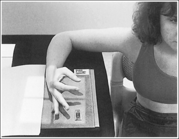
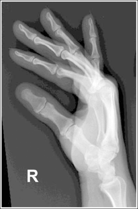
Image 26
The second through fifth metacarpals are superimposed.
• Superimpose the second through fifth metacarpals by palpating the patient's knuckles and placing them directly on top of one another.
• Verifying a lateral hand projection. On a lateral hand projection, a true lateral wrist position, represented by superimposition of the ulna and radius, is not always accomplished when the metacarpal midshafts are superimposed. Instead, the ulna is demonstrated slightly posterior to the radius. Because of this variation, a true lateral projection of the hand should be determined by judging the degree of superimposition of the second through fifth metacarpal midshafts and not the degree of ulnar and radial superimposition. If the metacarpal midshafts are not superimposed and the fifth metacarpal is demonstrated anterior to the second through fourth metacarpals, the hand was slightly externally rotated or supinated (see Image 26). The fifth metacarpal can be identified by its length; it is the shortest of the second through fifth metacarpals. If the metacarpal midshafts are not superimposed and the second metacarpal is demonstrated anterior to the third through fifth metacarpals, the hand was slightly internally rotated or pronated (see Images 27 and 28). The second metacarpal can also be identified by its length; it is the longest.
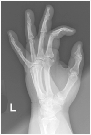
Image 27
The IP joints are open, and the phalanges are not foreshortened.
• The IP joint spaces are open and the phalanges are visible without foreshortening when the thumb is depressed and all the digits are positioned parallel with the IR.
The MP joints are at the center of the exposure field. The distal, middle, and proximal phalanges, the metacarpals, the carpals, and approximately 1 inch (2.5 cm) of the distal radius and ulna are included within the collimated field.
• Center a perpendicular central ray to the second MP joint to place it in the center of the collimated light field. Once the central ray is centered, open the longitudinal collimation to include the distal phalanges and the distal forearm. Transversely collimate to within 0.5 inch (1.25 cm) of the first and fifth finger's skin line.
• Either half of a 10- × 12-inch (24- × 30-cm) detailed screen-film IR placed crosswise or a single 8- × 10-inch (18- × 24-cm) screen-film or computed radiography IR placed lengthwise should be adequate to include all the required anatomic structures.
Optional Digit Positioning: Lateral Hand in Extension
The second through fifth digits are fully extended and superimposed (see Image 29). Density of the second through fifth digits and metacarpals is uniform, but the first metacarpal density is overexposed. The positioning analysis for the metacarpals is the same as for the fan lateral projection.
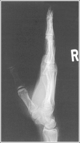
Image 29
Optional Digit Positioning: Lateral Hand in Flexion
The second through fifth digits are flexed and superimposed (see Image 30). Density of the second through fifth digits and metacarpals is uniform, but the first metacarpal density is overexposed. The positioning for the metacarpals is the same as for the fan lateral projection.
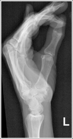
Image 30
Lateral Hand Projection Analysis
The second through fifth metacarpal midshafts are not superimposed, and the shortest (fifth) metacarpal is anterior to the third through fourth metacarpals. The hand was externally rotated. This image may also result if the central ray was positioned anterior to the MP joints to increase transverse collimation.
Correction
Internally rotate the patient's hand until the metacarpals are superimposed. Center the central ray to the MP joints.
Analysis
The second through fifth metacarpal midshafts are not superimposed, and the longest (second) metacarpal is anterior to the third through fifth metacarpals. The hand was internally rotated.
Analysis
The second through fifth metacarpal midshafts are not superimposed, and the longest (second) metacarpal is anterior to the third through fifth metacarpals. The hand was internally rotated.
Analysis
The digits are superimposed. This image was taken with the hand and fingers in full extension.
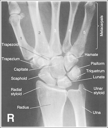
WRIST: POSTEROANTERIOR PROJECTION
See Figure 4-29 and Box 4-11.
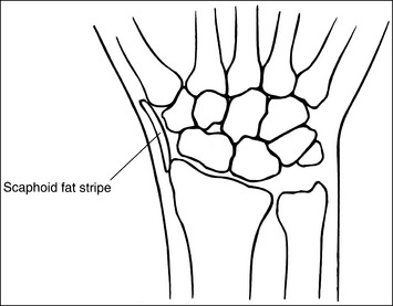
Contrast and density are adequate to demonstrate the scaphoid fat stripe.
• Significance of the scaphoid fat stripe. The scaphoid fat stripe is one of the soft tissue structures that should be visible on all PA wrist projections (Figure 4-30). It is convex and located just lateral to the scaphoid in an uninjured wrist. A change in the convexity of this stripe may indicate to the reviewer the presence of joint effusion or of a radial side fracture of the scaphoid, radial styloid process, or proximal first metacarpal.
The wrist is positioned in a PA projection. The radial and ulnar styloids are at the extreme lateral and medial edges, respectively, of each bone. The radioulnar articulation is open, and superimposition of the metacarpal bases is limited.
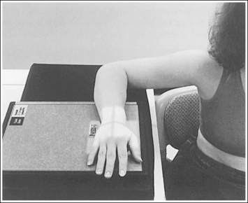
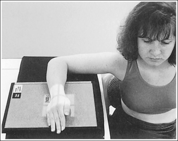
• Rotation of the wrist and forearm is controlled by the position of the hand, elbow, and humerus. A PA projection is accomplished by abducting the humerus until it is positioned parallel with the IR and the elbow is in a lateral projection. The hand is then pronated, placing the wrist in a PA projection (Figure 4-31).
• Detecting wrist rotation and radial styloid position. When the hand and wrist are rotated externally into an externally rotated PA oblique projection, the carpal bones and metacarpal bases located on the medial aspect of the wrist are superimposed, whereas those located laterally are not. The lateral interconnecting carpal and metacarpal joint spaces are also demonstrated (see Image 31). Internal rotation of the hand and wrist causes the laterally located carpal bones and metacarpal bases to be superimposed and increases visibility of the pisiform and hamate hook (see Image 32).
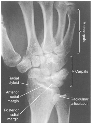
Image 31
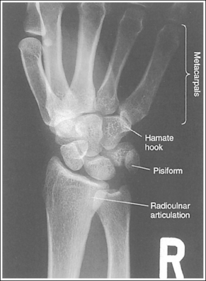
Image 32
• External and internal hand and wrist rotation also cause the radial styloid to rotate out of profile and closes the radioulnar articulation.
• Humerus and elbow positioning and ulnar styloid visualization. Humerus and elbow positioning determines the placement of the ulnar styloid. Abducting the humerus to position the elbow in a lateral projection with the humeral epicondyles aligned perpendicularly to the IR brings the ulnar styloid in profile and aligns the radius and ulna parallel with each other. The ulna and radius cross each other if the humerus is not abducted but is allowed to remain in a vertical position with the humeral epicondyles closer to parallel with the IR. This inaccurate positioning can be identified on a PA wrist projection by viewing the ulnar styloid, which is no longer demonstrated in profile (see Image 38).
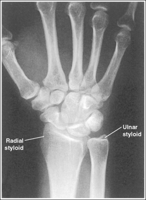
Image 38
The distal radius is demonstrated without foreshortening. The anterior and posterior articulating margins of the radius are nearly superimposed.
• The distal radial carpal articular surface is concave and slants approximately 11 degrees from posterior to anterior. Because the forearm is positioned parallel with the IR for a PA wrist projection, the slant of the distal radius causes the posterior radial margin to project slightly (0.25 inch or 0.6 cm) distal to the anterior radial margin, obscuring the radiocarpal joints.
• Distal radius superimposition: A PA wrist projection that demonstrates an excessive amount of the radial articulating surface, or if open radioscaphoid and radiolunate joint spaces are desired, view the distal radioulnar articulation to determine the correcting movement. The posterior edge of this surface is blunt, whereas the anterior edge is rounded. Study the distal end of a radial skeletal bone to familiarize yourself better with this difference. If a PA wrist projection is obtained that demonstrates the posterior radial margin distal to the anterior margin, the proximal forearm was elevated higher than the distal forearm (see Images 31 and 33). It should also be noted that when the wrist is medially rotated, the posterior radial surface is superimposed over the ulna. If the anterior radial margin is demonstrated distal to the posterior margin, the proximal forearm was positioned lower than the distal forearm. To superimpose the distal radial margins and to demonstrate radioscaphoid and radiolunate joints as open spaces (see Image 32), the proximal aspect of the forearm should be positioned slightly lower (5 to 6 degrees from horizontal) than the distal forearm.
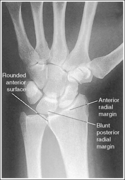
Image 33
• Positioning patient with thick proximal forearm.On a patient with a large muscular or thick proximal forearm, it may be necessary to allow the proximal forearm to extend off the IR or table to position the forearm parallel with the IR. If the patient is not positioned in this manner, the radius will be foreshortened, demonstrating an excessive amount of radial articular surface, and superimposition of the scaphoid and lunate onto the radius will be greater (see Image 33).
The second through fifth CM joint spaces are open. The scaphoid is only slightly foreshortened, and the lunate is trapezoidal.
• When the wrist is placed in a neutral nonflexed position, these three alignments are achieved. To place the wrist in a neutral position, flex the patient's fingers, flexing the hand until the metacarpals are angled to approximately 10 to 15 degrees with the IR.
• Effect of flexion and extension on carpal bones.View your own wrist in a PA projection with the hand extended flat against a hard surface. Note how the wrist is slightly flexed. Next, begin slowly flexing your hand and notice how the wrist moves from a flexed to an extended position with increased hand flexion. To understand how carpal bone position varies with wrist flexion and extension, study the drawings of the scaphoid, capitate, and lunate bones in Figure 4-32. Note how the positions of these carpals change with each movement. Also, study the position of the CM joint space in reference to a perpendicular central ray. Images 34 and 35 demonstrate PA wrist projections in flexion (the hand was extended) and extension (the hand was overflexed), respectively. Compare these images with the properly positioned wrist shown in Figure 4-29. Wrist flexion resulted in obscured third through fifth CM joint spaces, a severely foreshortened scaphoid that has taken a signet ring configuration (a large circle with a smaller circle within it), and a triangular lunate (see Image 34). Wrist extension has resulted in foreshortened metacarpals, closed second through third CM joint spaces, decreased scaphoid foreshortening, and a triangular lunate (see Image 35). Because the metacarpals are different lengths and may be positioned at different angles with the IR when the hand is flexed, it is necessary to position each metacarpal at a 10- to 15-degree angle to the IR to open all the CM joints.
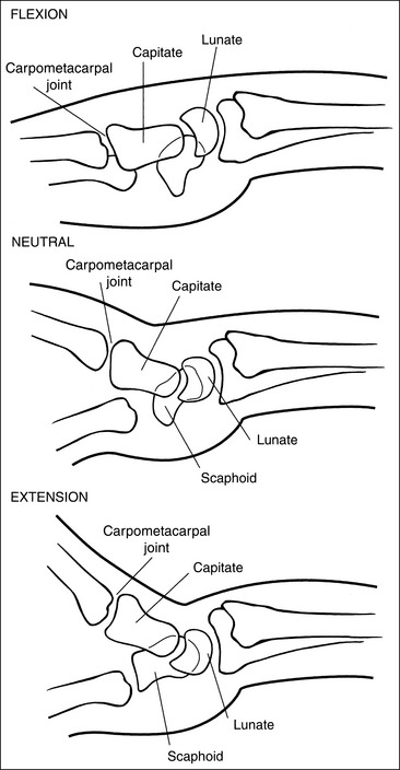
Figure 4-32 Lateral wrist in flexion (top), neutral position (middle), and extension (bottom). (From Martensen K II: Radiographic positioning and analysis of the wrist, In-Service Reviews in Radiologic Technology, 16[5], 1992.)
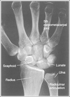
Image 34
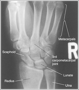
Image 35
The long axes of the third metacarpal and the midforearm are aligned with the long axis of the collimated light field. The scaphoid and half of the lunate are positioned distal to the radius.
• If the long axes of the third metacarpal and the midforearm are aligned with the long axis of the collimated light field, the patient's wrist has been placed in a neutral position. If a neutral position is not maintained for a PA wrist projection, the shapes of the scaphoid and the position of the lunate are altered (Figure 4-33; see Images 36 and 37). Radial deviation of the wrist causes the distal scaphoid to shift anteriorly (toward the palmar surface) and to demonstrate increased foreshortening as it forms a signet ring configuration. The lunate will shift medially, toward the ulna. In ulnar deviation, the distal scaphoid tilts posteriorly and demonstrates decreased foreshortening, and the lunate shifts laterally, toward the radius. Radial and ulnar deviated PA wrist projections may be specifically requested to demonstrate wrist joint mobility.
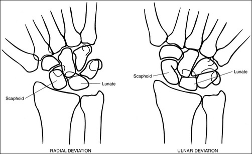
Figure 4-33 PA wrist in radial deviation (left) and ulnar deviation (right). (From Martensen K II: Radiographic positioning and analysis of the wrist, In-Service Reviews in Radiologic Technology, 16[5], 1992.)
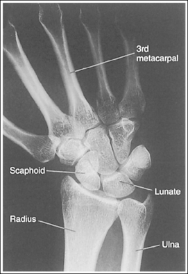
Image 36
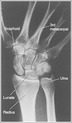
Image 37
The carpal bones are at the center of the exposure field. The carpal bones, one fourth of the distal ulna and radius, and half of the proximal metacarpals are included within the collimated field.
• The wrist joint is located at a level just distal to the palpable ulnar styloid. To obtain an image of the carpal bones with the least amount of distortion, place a perpendicular central ray at this level and centered to the midwrist area. Open the longitudinal collimation to include half of the metacarpals. Transversely collimate to within 0.5 inch (1.25 cm) of the wrist skin line.
• Either half of an 8- × 10-inch (18- × 24-cm) detailed screen-film or computed radiography IR or one third of a 10- × 12-inch (24- × 30-cm) detailed screen-film IR placed crosswise should be adequate to include all the required anatomic structures.
• Wrist examination taken to include more than one fourth of the forearm. When a wrist examination is requested to include more than one fourth of the distal forearm, the central ray should remain on the wrist joint, and the collimation field should be opened to demonstrate the desired amount of forearm. This method will result in an extended, unnecessary radiation field distal to the metacarpals. A lead strip placed over this extended radiation field protects the patient's phalanges and prevents backscatter from reaching the IR. The advantage of this method over centering the central ray proximal to the wrist joint is an undistorted demonstration of the carpal bones.
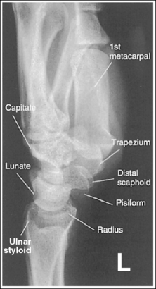
Effect of Upper Extremity Movements on Bony Components of the Wrist
The wrist is a very complex joint, with numerous bony components and movement possibilities. In an attempt to simplify the effect that different upper extremity movements have on the bony components, the following summary is offered. The positions of the elbow and hand affect forearm and wrist rotation and can be identified by the positions of the ulnar and radial styloid, respectively. When the elbow is in a lateral projection (humeral epicondyles aligned perpendicularly to IR), the ulnar styloid is in profile. When the hand is in a PA projection, the radial styloid is in profile.
It is the hand position that varies the shape of the scaphoid. If the wrist is flexed as a result of hand extension or is radially flexed, the scaphoid is foreshortened. If the wrist is extended as a result of hand flexion or is ulnar-flexed, the scaphoid is demonstrated with decreased foreshortening. The shape and location of the lunate also vary with the position of the wrist and hand. It becomes triangular with hand extension and flexion and changes position in reference to the distal radius with radial and ulnar flexion. In radial deviation the lunate is positioned distally to the radioulnar articulation, whereas in ulnar flexion it is positioned distally to the radius.
Because the shapes of the scaphoid and lunate can be changed with more than one positioning movement, it is necessary to evaluate mispositioned images carefully to determine which movement is causing the misposition. It is also possible for two corrections to be needed simultaneously to obtain accurate positioning. The accuracy of hand flexion and extension are easily identified by evaluating the CM joints. Wrist ulnar or radial deviation is identified by evaluating the alignment of the third metacarpal with the radius.
Posteroanterior Wrist Projection Analysis
The medially located carpal bones and metacarpals are superimposed, whereas the laterally located carpal and metacarpal joint spaces are open. The radioulnar articulation is closed, and the radial styloid is not in profile. The wrist was externally rotated. The posterior margin of the distal radius is too far distal to the anterior margin. The proximal forearm was slightly elevated. The ulnar styloid is in profile, indicating that the elbow and humerus were accurately positioned.
Correction
Internally rotate the hand until the wrist is in a PA projection, and depress the proximal forearm. For a patient with a thick proximal forearm, allow the proximal forearm to hang off the IR and/or the table.
Analysis
The laterally located carpals and metacarpals are superimposed, and the pisiform and hamate hook are visualized. The radioulnar articulation is closed. The wrist was internally rotated. The ulnar styloid is in profile, indicating accurate elbow and humerus positioning, and the distal radial articular surfaces are directly superimposed over each other, demonstrating open radiolunate and radioscaphoid joint spaces. The proximal forearm was positioned slightly lower than the distal forearm.
Analysis
The posterior margin of the distal radius is too far distal to the anterior margin. The posterior margin can be identified by the blunt, posterior ulnar articulating edge. The forearm was foreshortened, with the proximal forearm positioned higher than the distal forearm.
Correction
Lower the proximal forearm until it is parallel with the IR. If you desire a superimposed distal radial articular surface, which will demonstrate open radiolunate and radioscaphoid joint spaces, position the proximal forearm slightly lower (5 to 6 degrees from horizontal) than the distal forearm. For a patient with a thick proximal forearm, allow the proximal forearm to extend beyond the IR and/or table.
Analysis
The scaphoid demonstrates excessive foreshortening and has a signet ring configuration, the CM joints are obscured, and the lunate is triangular but is properly positioned distal to the radius. Two hand mispositions will cause this scaphoid shape—radial deviation and hand extension. Because the third metacarpal is aligned with the midforearm and the lunate is properly positioned distal to the radius, radial deviation can be eliminated as the positional problem. Hand extension (wrist flexion) is the cause of this mispositioning.
Correction
Curl the patient's fingers, flexing the hand until the second through fifth metacarpals are angled at approximately 10 to 15 degrees with the IR.
Analysis
The scaphoid is demonstrated with decreased foreshortening, and the second through third metacarpals are superimposed over the CM joints. The lunate is properly positioned distally to the radioulnar articulation. Two hand mispositions will cause this scaphoid shape, ulnar deviation and hand overflexion (metacarpals angled at more than 10 to 15 degrees with the IR). Because the third metacarpal is aligned with the midforearm and the lunate is properly positioned distally to the radioulnar articulation, ulnar deviation can be eliminated as the positional problem. Hand overflexion (wrist extension) is the cause of this misposition. The fifth CM joint is open because the fifth metacarpal is shorter and was placed at less of an angle to the IR than the other metacarpals when the hand was flexed.
Correction
Extend fingers and hand until the second through fifth metacarpals are angled at 10 to 15 degrees with the IR.
Analysis
The scaphoid demonstrates increased foreshortening, the lunate is positioned mostly distally to the ulna, and the third metacarpal is not aligned with the long axis of the midforearm. Because the scaphoid foreshortens with both hand extension and radial deviation, you can determine the correct repositioning movement for this image by evaluating the alignment of the third metacarpal with the midforearm and the openness of the CM joint spaces. The third metacarpal is not aligned with the midforearm and the scaphoid demonstrates increased foreshortening, so you can conclude that the patient was in radial deviation. Because the CM joint spaces are open, the hand was properly flexed.
Correction
Ulnar-deviate the wrist until the third metacarpal and the midforearm are aligned, placing the hand and wrist in a neutral position. If a radial-deviated PA wrist projection is desired to evaluate patient mobility, no correction movement is required.
Analysis
The scaphoid is demonstrated with decreased foreshortening, the lunate is entirely positioned distal to the radius, and the third metacarpal is not aligned with the midforearm. All these positioning points indicate that the wrist was in ulnar deviation for the image. Because the CM joint spaces are open, you can conclude that the hand was accurately flexed.
Correction
Radially deviate the wrist until the third metacarpal is aligned with the midforearm, placing the hand and wrist in a neutral position. If an ulnar-deviated PA wrist image is desired to evaluate patient mobility, no correcting movement is required.
Analysis
This image has many positioning problems. First, the radioulnar articulation is closed and the lateral intercarpal joints are open while the medial intercarpal joints are closed, indicating that the hand and wrist were externally rotated. Second, the ulnar styloid is not in profile, indicating that the elbow and humerus were mispositioned. Next, the distal radius is foreshortened. Note how the articulating surface is demonstrated with the posterior margin far too distal to the anterior margin. The proximal forearm was positioned higher than the distal forearm. Finally, the scaphoid demonstrates excessive foreshortening, and the fourth and fifth CM joints are obscured. The image was taken with the wrist in slight external rotation, with the fourth and fifth metacarpals positioned at less than a 10- to 15-degree angle to the IR, although the second and third distal metacarpals were elevated accurately.
Correction
Flex the elbow and abduct the humerus 90 degrees, placing the entire arm on the same horizontal plane. Slightly depress the proximal forearm. Internally rotate the hand and wrist until they are positioned in a PA projection. Curl the fingers, flexing the hand until all the metacarpals are angled at 10 to 15 degrees to the IR.
WRIST: POSTEROANTERIOR OBLIQUE PROJECTION (EXTERNAL ROTATION)
See Figure 4-34 and Box 4-12.
Contrast and density are adequate to demonstrate the scaphoid fat stripe.
• The scaphoid fat stripe is one of the soft tissue structures that should be visible on all PA oblique wrist projections. It is convex and located just lateral to the scaphoid on an uninjured wrist (see Figure 4-30). A change in the shape of this fat stripe or in its proximity to the scaphoid may indicate joint effusion or a radial side fracture.
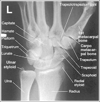
The wrist has been externally rotated to a 45-degree PA oblique projection. The trapezoid and trapezium are demonstrated without superimposition, and the trapeziotrapezoidal joint space is open. The scaphoid tuberosity and waist are demonstrated in profile. Only a small degree of trapezoid and capitate superimposition is present.
• To accomplish a PA oblique wrist projection, begin with the wrist in a PA projection, with the humerus and the forearm on the same horizontal plane. Externally rotate the hand and wrist until the wrist forms a 45-degree angle with the IR (Figure 4-35). When judging the degree of wrist obliquity, it is best to view the wrist and not the hand. The obliquity of the hand and wrist are not always equal when they are rotated, especially if the humerus and forearm are not positioned on the same horizontal plane for the image.
• Determining the accuracy of wrist obliquity. On a PA wrist projection (see Image 39), the trapezoid and trapezium are superimposed. Placing the wrist in a 45-degree externally rotated PA oblique projection draws the trapezium from beneath the trapezoid, providing clear visualization of both carpal bones and the joint space (trapeziotrapezoidal) between them. The PA oblique projection also rotates the scaphoid tuberosity and waist into profile. The relationships between the trapezoid and trapezium and the trapezoid and capitate are used to discern an accurate PA oblique wrist projection. If the wrist is underrotated, the trapezoid and trapezium are superimposed, the trapeziotrapezoidal joint space is obscured, and the trapezoid demonstrates minimal capitate superimposition (see Image 40). If wrist obliquity is more than 45 degrees, the trapezium demonstrates minimal trapezoidal superimposition, the capitate is superimposed by the trapezoid, and the trapeziotrapezoidal joint space is obscured (see Image 41).
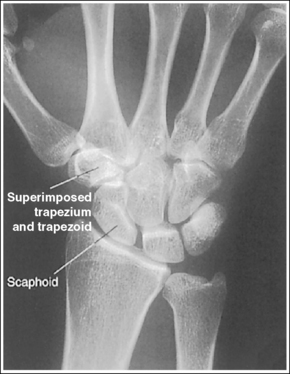
Image 39
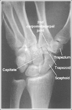
Image 40
Image 41
The second CM and the scaphotrapezoidal joint spaces are demonstrated.
• For the PA wrist projection, the CM joints are opened by flexing the hand until the metacarpals are at a 10- to 15-degree angle to the IR. When the hand and wrist are placed in obliquity, the same metacarpal tilt must be maintained to open the second CM and scaphotrapezoidal joint spaces. If the distal second metacarpal is positioned too far away from the IR, a portion of the metacarpal (MC) superimposes the trapezoid, closing the second CM and scaphotrapezoidal joints (see Image 40).
The long axes of the third metacarpal and midforearm are aligned with the long axis of the collimated field. The scaphoid tuberosity and waist are demonstrated in profile and are not positioned directly next to the radius.
• If the long axes of the third metacarpal and midforearm are aligned with the long axis of the collimation field, the patient's wrist is placed in a neutral position. Radial deviation increases the foreshortening of the scaphoid, preventing visualization of the scaphoid tuberosity and waist, and positions the scaphoid directly next to the radius (see Image 42). Ulnar deviation decreases scaphoid foreshortening (see Image 43).
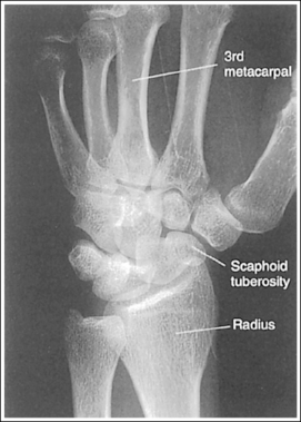
Image 42
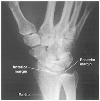
Image 43
The distal radius is demonstrated without foreshortening. The anterior and posterior margins of the radius are nearly superimposed.
• The distal radial carpal articular surface is concave and slants approximately 11 degrees from posterior to anterior when the radius and ulna are positioned parallel with the IR. Because the forearm is positioned parallel with the IR for a PA oblique wrist projection, the slant of the distal radius causes the posterior margin to be projected slightly (0.25 inch or 0.6 cm) distal to the anterior radial margin, obscuring the radiocarpal joints.
If an image is obtained that demonstrates an excessive amount of the radial articulating surface, or if open radioscaphoid and radiolunate joint spaces are desired, you should view the distal radioulnar articulation to determine the correcting movement. The radial surface superimposed over the ulna is associated with the posterior radial margin.
• Distal radius margin superimposition. If a PA oblique projection is obtained that demonstrates the posterior radial margin too far distal to the anterior margin, the proximal forearm was elevated higher than the distal forearm (see Image 43). If the anterior radial margin is demonstrated distal to the posterior margin, the proximal forearm was positioned lower than the distal forearm. To demonstrate open radioscaphoid and radiolunate joint spaces (see Image 44), position the proximal forearm slightly (5 to 6 degrees) lower than the distal forearm.
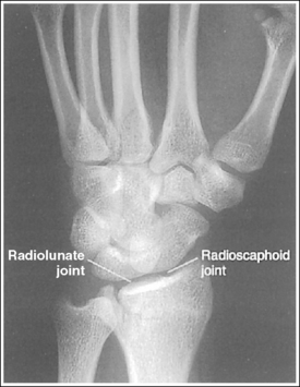
Image 44
• Positioning patient with thick proximal forearm. For the patient with a large muscular or thick proximal forearm, allow the proximal forearm to extend beyond the IR or table to position it parallel with the IR. If the patient is not positioned in this manner, the radius is foreshortened, demonstrating an excessive amount of radial articular surface, and superimposition of the scaphoid and lunate onto the radius is increased.
The ulnar styloid is in profile at the far medial edge.
• The position of the humerus and elbow determines the placement of the ulnar styloid. The ulnar styloid is demonstrated in profile when the patient's humerus is abducted to align the humeral epicondyles perpendicular to the IR and place the elbow in a lateral position. If the humerus is not abducted to this degree, the ulnar styloid is no longer demonstrated in profile.
The carpal bones are at the center of the exposure field. The carpal bones, one fourth of the distal ulna and radius, and half of the proximal metacarpals are included within the collimated field.
• The wrist joint is located at the base of the first proximal metacarpal. To obtain a PA oblique projection of the carpal bones with the least amount of distortion, place a perpendicular central ray at this level and centered with the midwrist area. Open longitudinal collimation to include half of the metacarpals. Transversely collimate to within 0.5 inch (1.25 cm) of the wrist skin line.
• Either half of an 8- ×10-inch (18- × 24-cm) detailed screen-film or computed radiography IR or one third of a 10- × 12-inch (24- × 30-cm) detailed screen-film IR placed crosswise should be adequate to include all the required anatomic structures.
Posteroanterior Oblique Wrist Projection Analysis
The trapezoid and trapezium are superimposed, and the scaphoid tuberosity is not demonstrated in profile. This is a PA projection.
Analysis
The trapezoid and trapezium are partially superimposed, obscuring the trapeziotrapezoidal joint space. Trapezoid capitate superimposition is minimal. The wrist was rotated less than 45 degrees. The second CM and scaphotrapezoidal joint spaces are closed. The distal second metacarpal was positioned too far away from the IR.
Correction
Externally rotate the wrist until it forms a 45-degree angle with the IR. Depress the distal second metacarpal until it is positioned at a 10- to 15-degree angle to the IR.
Analysis
Trapezoid and trapezium are partially superimposed, obscuring the trapeziotrapezoidal joint space. The trapezoid demonstrates excessive capitate superimposition. The wrist obliquity was more than 45 degrees.
Analysis
The third metacarpal and midforearm are not aligned, the scaphoid is foreshortened, and the scaphoid tuberosity is situated next to the radius. The wrist was radially flexed.
Correction
Ulnar-deviate the wrist until the long axes of the third metacarpal and the midforearm are aligned.
Analysis
The posterior margin of the distal radius is quite distal to the anterior margin, the third metacarpal and midforearm are not aligned, and the scaphoid demonstrates little foreshortening. The proximal forearm was elevated, and the wrist was ulnar-flexed.
Correction
Lower the proximal forearm until the forearm is parallel with the IR. For a patient with a muscular or thick proximal forearm, it may be necessary to allow the proximal forearm to hang off the IR or table to obtain a parallel forearm. Radial-deviate the wrist until the third metacarpal and midforearm are aligned.
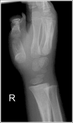
WRIST: LATERAL PROJECTION (LATEROMEDIAL)
See Figure 4-36 and Box 4-13.
Contrast and density are adequate to demonstrate the pronator fat stripe and surrounding posterior wrist soft tissue.
• The pronator fat stripe is one of the soft tissue structures that should be demonstrated on all lateral wrist projections (Figure 4-37). It is located parallel to the anterior (volar) surface of the distal radius, is normally convex, and lies within 0.25 inch (0.6 cm) of the radial cortex. Bowing or obliteration of this fat stripe may be the only indication of a subtle radial fracture.
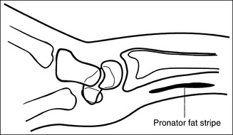
Figure 4-37 Location of pronator fat stripe. (From Martensen K II: Radiographic positioning and analysis of the wrist, In-Service Reviews in Radiologic Technology, 16[5], 1992.)
• The soft tissue that surrounds the posterior (dorsal) aspect of the wrist should also be visible. This posterior soft tissue is convex on the uninjured wrist. To the reviewer, a straightening or concave appearance of this surface may indicate swelling and injury.
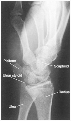
The wrist is in a lateral projection. The anterior aspect of the distal scaphoid and pisiform are aligned, and the radius and ulna are superimposed.
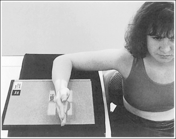
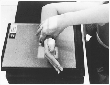
• A lateral projection of the wrist is accomplished by flexing the elbow 90 degrees and abducting the humerus until it is parallel with the IR, placing the entire arm on the same horizontal plane. Rotate the wrist into a lateral projection with its ulnar (medial) aspect against the IR (Figure 4-38). To ensure a true lateral projection, place the palmar aspect of your thumb and forefinger against the anterior and posterior aspects, respectively, of the patient's wrist joint, as shown in Figure 4-39. Adjust wrist rotation until your thumb and finger are aligned perpendicular to the IR.
• Detecting wrist rotation. The relationship between the pisiform and distal aspect of the scaphoid can best be used to discern whether a lateral wrist projection has been obtained. On a lateral projection, these two carpals should be superimposed, with their anterior aspects aligned. When the wrist is rotated, the anteroposterior relationship between the distal scaphoid and pisiform changes, and the pronator fat stripe is obscured. If the anterior aspect of the distal scaphoid is positioned posterior to the anterior aspect of the pisiform, the patient's wrist was externally rotated (see Image 45). If the anterior aspect of the distal scaphoid is positioned anterior to the anterior aspect of the pisiform, the patient's wrist was internally rotated (see Images 46 and 47). A second method of determining how to reposition a rotated lateral wrist projection uses the radius and ulna. The ulna is positioned anterior to the radius when the wrist was externally rotated and the ulna is positioned posterior to the radius when the wrist was internally rotated. Because the exact amount of superimposition of the radius and ulna depends on the position of the humerus, and their poor positioning is not as sensitive, you should always view the pisiform and distal scaphoid relationship when determining whether the wrist is in a lateral projection.
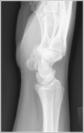
Image 45
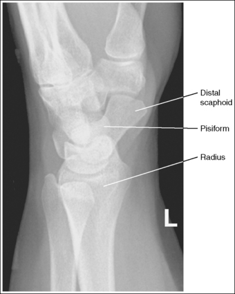
Image 46
• Mediolateral wrist projection. Routinely, the lateral wrist projection is taken with the ulnar side of the wrist against the IR. If, instead, the radial side of the wrist was placed against the IR (mediolateral projection), the ulna and pisiform are visualized anterior to the radius and scaphoid, respectively, and the ulnar styloid is demonstrated in profile anteriorly (see Image 48).
The carpal bones do not indicate radial or ulnar deviation. The distal aspect of the distal scaphoid is aligned with the distal aspect of the pisiform.
• To obtain a neutral lateral wrist projection, align the long axes of the third metacarpal and the midforearm parallel with the IR. When the proximal forearm is higher or lower than the distal forearm, the wrist is radial-deviated or ulnar-deviated, respectively. In radial and ulnar deviation the distal scaphoid moves but the pisiform's position remains relatively unchanged. Radial deviation of the wrist forces the distal scaphoid to move anteriorly and proximally (Figure 4-40), causing the distal aspect of the distal scaphoid to be positioned proximal to the distal aspect of the pisiform (see Image 49). Ulnar deviation shifts the distal scaphoid posteriorly and distally (see Figure 4-40), causing the distal aspect of the distal scaphoid to be positioned distal to the distal aspect of the pisiform (see Image 50). The degree of pisiform and distal scaphoid separation is usually very small, because you would be unlikely to position a patient in maximum wrist deviation without being aware of the positioning error. To obtain optimal lateral wrist projections, however, you must learn to eliminate even small degrees of deviation.
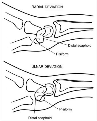
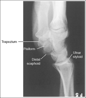
Image 49
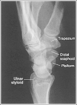
Image 50
• Positioning patient with thick proximal forearm. For a patient with a large muscular or thick proximal forearm, it may be necessary to allow the proximal forearm to hang off the IR or table to maintain a neutral wrist position (Figure 4-41). If the patient is not positioned in this manner, radial deviation of the wrist will result. If the proximal forearm does not remain level but is allowed to depress lower than the distal forearm in this situation, ulnar deviation will result.
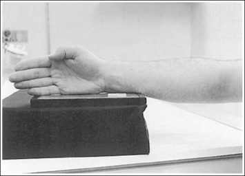
The long axis of the first metacarpal is aligned parallel with the forearm.
• If the long axis of the first metacarpal is positioned adjacent to the second metacarpal and aligned parallel with the forearm, the patient's wrist is placed in a neutral position.
• When the wrist is flexed or extended, the positions of the scaphoid and lunate are altered. In wrist flexion the lunate and distal scaphoid tilt anteriorly (see Image 51). In wrist extension the lunate and distal scaphoid tilt posteriorly (see Image 52). Flexion and extension, lateral wrist projections may be specifically requested to demonstrate wrist joint mobility.
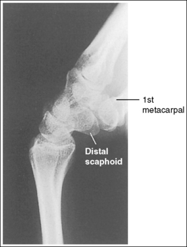
Image 51
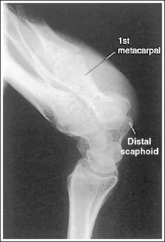
Image 52
The ulnar styloid is demonstrated in profile posteriorly.
• When the humerus and elbow are positioned, the placement of the ulna styloid changes. The ulnar styloid is demonstrated in profile when the patient's elbow is in a lateral projection, with the humerus abducted and the humeral epicondyles aligned perpendicularly to the IR. If the humerus is not abducted to this degree, the ulnar styloid will not be demonstrated in profile (Images 45 and 53).
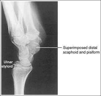
Image 53
• Lateral wrist projection with no forearm rotation. In contrast to positioning the forearm and humerus on the same horizontal plane for a lateral wrist projection, Epner and colleagues1 have suggested that a lateral wrist projection be taken with zero forearm rotation. For this to be accomplished the humerus is not abducted and the elbow is placed in an AP projection (Figure 4-42). Such positioning rotates the ulnar styloid out of profile, demonstrating it distal to the midline of the ulnar head (see Images 45 and 53). Because forearm rotation has been eliminated, the ulnar head also shifts closer to the lunate. Epner and associates1 have stated that this positioning allows for more accurate measuring of the ulnar length. Department policy determines which humerus positioning is performed in your facility.
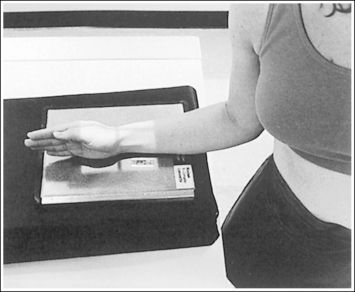
The trapezium is demonstrated without superimposition of the first proximal metacarpal.
• To obtain optimal demonstration of the trapezium, lower the distal first metacarpal until it is at the same level as the second metacarpal. This positioning places the trapezium and metacarpal parallel with the IR, demonstrating them without superimposition. If the distal first metacarpal is not lowered, it is foreshortened, and its proximal aspect is superimposed over the trapezium (see Image 54).
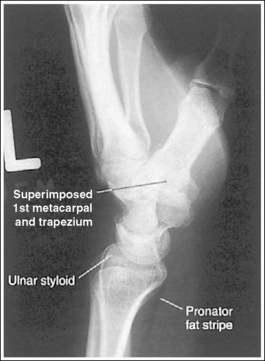
Image 54
The carpal bones are at the center of the exposure field. The carpal bones, one fourth of the distal ulna and radius, and half of the proximal metacarpals are included within the collimated field.
• In a lateral projection the wrist joint is located just proximal to the first metacarpal base. To obtain an image of the carpal bones with the least amount of distortion, place a perpendicular central ray at this level and centered to the midwrist area. Open the longitudinal collimation to include half of the metacarpals. Transversely collimate to within 0.5 inch (1.25 cm) of the wrist skin line.
• Either half of an 8- × 10-inch (18- × 24-cm) detailed screen-film or computed radiography IR or one third of a 10- × 12-inch (24- × 30-cm) detailed screen-film IR placed crosswise should be adequate to include all the required anatomic structures.
• Wrist examination that includes more than one fourth of the forearm. When a wrist examination is requested to include more than one fourth of the distal forearm, the central ray should remain on the wrist joint, and the collimation field should be opened to demonstrate the desired amount of forearm. This method results in an extended, unnecessary radiation field distal to the metacarpals. A lead strip placed over this extended radiation field protects the patient's phalanges and prevents any possible backscatter from reaching the IR. The advantage of this method over centering the central ray proximal to the wrist joint is an undistorted demonstration of the carpal bones. A lateral wrist projection taken with the central ray positioned proximal to the wrist joint demonstrates the distal scaphoid projecting distal to the pisiform (see Image 50).
Lateral Wrist Projection Analysis
The anterior aspect of the pisiform is shown anterior to the anterior aspect of the distal scaphoid. The wrist was externally rotated. The proximal first metacarpal is partially superimposed over the trapezium. The first metacarpal was not positioned parallel with the forearm. The ulnar styloid is not positioned in profile but is demonstrated projecting distally to the midline of the ulnar head. This ulnar positioning indicates that the humerus was positioned without abduction, as shown in Figure 4-42.
Correction
Internally rotate the wrist until the wrist is in a lateral position, and depress the distal metacarpal until the metacarpal is aligned parallel with the forearm. Adjust the patient's humerus to meet your department protocol. If the ulnar styloid is to be demonstrated in profile, abduct the humerus and flex the elbow 90 degrees, placing the forearm and humerus on the same horizontal plane. If department protocol requires that a lateral wrist image be taken without humeral abduction, no correction movement is needed. Consistency in arm position is important for evaluating ulnar length.
Analysis
The anterior aspect of the distal scaphoid is anterior to the anterior aspect of the pisiform, and the radius is anterior to the ulna. The wrist was internally rotated.
Analysis
The ulna and pisiform are demonstrated anterior to the radius and scaphoid, respectively, and the ulnar styloid is demonstrated in profile anteriorly. The radial side of the wrist was placed against the IR (mediolateral projection).
Correction
Externally rotate the hand and wrist until the ulnar side of the wrist is placed against the IR if a lateromedial projection is desired.
Analysis
The distal aspect of the pisiform is demonstrated distal to the distal aspect of the distal scaphoid. Two possible positioning errors cause such an image. Either the central ray was not centered with the wrist joint but was positioned distally, or the wrist was in radial deviation. Note that the ulnar styloid is not in profile but is projecting distally to the midline of the ulnar head. This ulnar positioning indicates that the patient was positioned without humerus abduction, as demonstrated in Figure 4-42. The proximal first metacarpal is partially superimposed over the trapezium. The metacarpal was not aligned parallel with the IR.
Correction
Center the central ray with the wrist joint, which is located just proximal to the trapezium. Position the wrist in a neutral position by aligning the long axes of the third metacarpal and midforearm parallel with the IR. Depress the distal metacarpal until the first metacarpal is aligned parallel with the IR.
Analysis
The distal aspect of the distal scaphoid is demonstrated distal to the distal aspect of the pisiform. Two possible positioning errors cause such a problem. Either the wrist was in ulnar deviation or the central ray was not centered with the wrist joint but was positioned to the midforearm.
Correction
Place the wrist in a neutral position by aligning the long axes of the third metacarpal and the midforearm parallel with the IR. Center the central ray with the wrist joint, which is located just proximal to the trapezium.
Analysis
The first metacarpal is not aligned parallel with the midforearm. The wrist was flexed anteriorly.
Correction
If a neutral position is desired, align the long axis of the first metacarpal parallel with the midforearm. If a wrist flexion image was taken to evaluate wrist mobility, no correction movement is required.
Analysis
The first metacarpal is not aligned parallel with the midforearm. The wrist is extended posteriorly.
Correction
If a neutral position is desired, align the first metacarpal parallel with the midforearm. If a wrist extension image was taken to evaluate wrist mobility, no correction movement is required.
Analysis
The pisiform and the distal scaphoid are positioned accurately for a lateral wrist projection. The ulnar styloid is not positioned in profile but is demonstrated projecting distally to the midline of the ulnar head. This ulnar positioning indicates that the humerus was positioned without abduction, as shown in Figure 4-42.
Correction
Adjust the patient's humerus to meet your department protocol. If the ulnar styloid is to be demonstrated in profile, abduct the humerus and flex the elbow 90 degrees, placing the forearm and humerus on the same horizontal plane. If department protocol requires that a lateral wrist projection be taken without humeral abduction, no correction movement is needed. Consistency in arm position is important to evaluating ulnar length.
Analysis
The first proximal metacarpal is superimposed over the trapezium. The thumb was not positioned parallel with the midforearm but was pointing upward. The ulnar styloid is not in profile.
Correction
Depress the patient's distal thumb until the metacarpal is aligned parallel with the midforearm. Adjust the patient's humerus to meet your department protocol. If the ulnar styloid is to be demonstrated in profile, abduct the humerus and flex the elbow 90 degrees, placing the forearm and humerus on the same horizontal plane. If department protocol requires that a lateral wrist projection be taken without humeral abduction, no correction movement is needed.